KGT 305 M - Saw METABO - Free user manual and instructions
Find the device manual for free KGT 305 M METABO in PDF.

User questions about KGT 305 M METABO
0 question about this device. Answer the ones you know or ask your own.
Ask a new question about this device
Download the instructions for your Saw in PDF format for free! Find your manual KGT 305 M - METABO and take your electronic device back in hand. On this page are published all the documents necessary for the use of your device. KGT 305 M by METABO.
USER MANUAL KGT 305 M METABO
Original Instructions
1. Declaration of Conformity
3. General Safety Instructions
4. Special Safety Instructions
6. Unpacking, assembly, installation and
7. The device in detail
9. Operation / Use as chop and mitre saw
9. Operation / Use as table saw
We, being solely responsible, hereby declare that these chop and mitre saws and table saws, identified by type and serial number *1), meet all relevant requirements of directives *2) and standards *3). Test report *4), Issuing testing authority *5), Technical documents for *6) - see page 4. The chop and mitre saw and table saw is suitable for longitudinal and transverse cutting, angled cutting, mitre cuts and double mitre cuts. Only materials for which the respective saw blade is suited may be machined (approved saw blades see chapter 13. Accessories). The permitted dimensions of the workpieces must be complied with (see chapter 17. Technical Data). Workpieces with round or irregular cross-section (such as firewood) must not be cut, as they cannot be held securely during the cutting process. When sawing a thin workpiece laid on its edge, a suitable guide must be used for firm support. Do not use machine for cutting slots / inserts (groove ending in the workpiece). Do not use machine for notches or grooves. Any other use does not comply with the intended purpose. Unspecified use, modification of the device or use of parts that have not been tested and approved by the manufacturer can cause unforeseeable damage! Where applicable, follow the legal directives or regulations for the prevention of accidents. For your own protection and for the protection of your electrical tool, pay attention to all parts of the text that are marked with this symbol! WARNING! When using electric tools basic safety precautions should always be followed to reduce the risk of fire, electric shock and personal injury including the following. Read all these instructions before attempting to operate this prod-ct and save these instructions. WARNING – Reading the operating instructions will reduce the risk of injury. Pass on your power tool only together with these documents. General Power Tool Safety Warnings WARNING – Read all safety warnings and instructions. Failure to follow all instructions listed below may result in electric shock, fire and/or serious injury. Save all warnings and instructions for future reference!
3.1 Work Area Safety
a) Keep work area clean and well lit. Cluttered or dark areas invite accidents. b) Do not operate power tools in explosive atmospheres, such as in the presence of flammable liquids, gases or dust. Power tools create sparks which may ignite the dust or fumes. c) Keep children and bystanders away while operating a power tool. Distractions can cause you to lose control. Do not let other people, particularly children, touch the power tool or cable.
3.2 Electrical Safety
a) Power tool plugs must match the outlet. Never modify the plug in any way. Do not use any adapter plugs with earthed (grounded) power tools. Unmodified plugs and matching outlets will reduce risk of electric shock. b) Avoid body contact with earthed or grounded surfaces, such as pipes, radiators, ranges and refrigerators. There is an increased risk of electric shock if your body is earthed or grounded. c) Do not expose power tools to rain or wet conditions. Water entering a power tool will increase the risk of electric shock. d) Do not abuse the cord. Never use the cord for carrying, pulling or unplugging the power tool. Keep cord away from heat, oil, sharp edges or moving parts. Damaged or entangled cords increase the risk of electric shock. e) When operating a power tool outdoors, use an extension cord suitable for outdoor use. Use of a cord suitable for outdoor use reduces the risk of electric shock. f) If operating a power tool in a damp location is unavoidable, use a residual current device (RCD) protected supply. Use of an RCD reduces the risk of electric shock.
a) Stay alert, watch what you are doing and use common sense when operating a power tool. Do not use a power tool if you are tired or not concentrating or are under the influence of drugs, alcohol or medication. A moment of inattention while operating power tools may result in serious personal injury. b) Use personal protective equipment. Always wear eye protection. Protective equipment such as dust mask, non-skid safety shoes, hard hat, or hearing protection used for appropriate conditions will reduce personal injuries. c) Prevent unintentional starting. Make sure that the power tool is switched off before you connect it to the power supply, lift or carry it. Carrying power tools with your finger on the switch or energising power tools that have the switch on invites accidents. d) Remove any adjusting key or wrench before turning the power tool on. A wrench or a key left attached to a rotating part of the power tool may result in personal injury. e) Do not overreach. Keep proper footing and balance at all times. This enables better control of the power tool in unexpected situations. f) Dress properly. Do not wear loose clothing or jewellery. Keep your hair and clothing away from moving parts. Loose clothes, jewellery or long hair can be caught in moving parts. g) If devices are provided for the connection of dust extraction and collection facilities, ensure these are connected and properly used. Use of dust extraction can reduce dust- related hazards. h) Do not let familiarity gained from frequent use of tools allow you to become complacent and ignore tool safety principles. A careless action can cause severe injury within a fraction of a second.
3.4 Power Tool Use and Care
a) Do not force the power tool. Use the correct power tool for your application. Use the correct power tool. Do not use the power tool for purposes, for which it is not designed. Do not use low-power machines for heavy-duty work. The correct power tool will do the job better and safer at the rate for which it was designed. b) Do not use the power tool if the switch does not turn it on and off. Any power tool that cannot be controlled with the switch is dangerous and must be repaired. c) Disconnect the plug from the power source and/or the battery pack from the tool before making any adjustments, changing accessories, or storing tools. Such preventive safety measures reduce the risk of starting the power tool accidentally. d) Store idle power tools out of the reach of children. Unused power tools should be stored in a dry, elevated or closed location out of the reach of children. Do not allow persons unfamiliar with the power tool or these instructions to operate the power tool. Power tools are dangerous in the hands of untrained users. e) Maintain power tools and accessories with care. Check for misalignment or binding of moving parts, breakage of parts and any other condition that may affect the power tool's operation. If damaged, have the power tool repaired before use. Follow the instructions for lubrication and tool replacement. Many accidents are caused by poorly maintained power tools. f) Keep cutting tools sharp and clean. Properly maintained cutting tools with sharp cutting edges are less likely to bind and are easier to control. g) Use the power tool, accessories, tool bits etc. in accordance with these instructions. Take into account the working conditions and the work to be performed. Use of the power tool for operations different from those intended could result in a hazardous situation. h) Keep handles and grasping surfaces dry, clean and free from oil and grease. Slippery handles and grasping surfaces do not allow for safe handling and control of the tool in unexpected situations.
a) Have your power tool serviced by a qualified repair person using only identical replacement parts. This will ensure that the safety of the power tool is maintained. a) Chop, mitre and table saws are designed for cutting wood or wood-like products, they cannot be used to cut ferrous materials such as rods, bars, screws, etc. Abrasive dust causes moving parts such as the lower guard to jam. Sparks from abrasive cutting will burn the lower guard, the kerf insert and other plastic parts. b) When using as chop and mitre saw: Fix the workpiece with clamps. Do not use this saw to cut pieces, which are too small to clamp. If your hand is placed too close to the saw blade, there is an increased risk of injury from blade contact. c) When used as a chop and mitre saw: The workpiece must be immobile and tightly clamped. Do not feed the workpiece into the blade or cut "freehand" in any way. Unrestrained or moving workpieces could be thrown at high speeds, causing injury. d) Never cross your hand over the intended line of cutting either in front or behind the saw blade. Supporting the workpiece "cross handed" i.e. holding the workpiece to the right of the saw blade with your left hand or vice versa is very dangerous. e) When used as a chop and mitre saw: Do not grab the rotating blade behind the limit stop. Do not undercut a safety distance of 100 mm between the hand and the rotating saw blade (applies to both sides of the saw blade, e.g. when removing wood scraps). The Contents
1. Declaration of Conformity
3. General Safety Instructions
proximity of the spinning saw blade to your hand may not be obvious and you may be seriously injured. f) When used as a chop and mitre saw: Check the workpiece before cutting. If the workpiece is bowed or warped, clamp it with the outside bowed face toward the fence. Always make certain that there is no gap between the workpiece, fence and table along the line of the cut. Bent or warped workpieces can twist or shift and may cause binding on the spinning saw blade while cutting. There should be no nails or foreign objects in the workpiece. g) Do not use the saw until the table is clear of all tools, wood scraps, etc., except for the workpiece. Small debris or loose pieces of wood or other objects that contact the revolving blade can be thrown with high speed. h) Cut only one workpiece at a time. Stacked multiple workpieces cannot be adequately clamped or braced and may bind on the blade or shift during cutting.
i) Before use, ensure that the machine is
standing on a level, solid work surface. A level and solid work surface reduces the risk that the machine will become unstable. j) When used as a chop and mitre saw: Plan your work. Every time you change the bevel or mitre angle setting, make sure the adjustable fence is set correctly to support the workpiece and will not interfere with the blade or the guarding system. Without turning the tool "ON" and with no workpiece on the table, move the saw blade through a complete simulated cut to assure there will be no interference or danger of cutting the fence. k) Provide adequate support such as table extensions, saw horses, etc. for workpieces that are wider or longer than the table top. Workpieces, which are longer or wider than the machine's table, may tip if they are not firmly supported. If a cut off piece of wood or the workpiece tips, it can lift the protective cover or can spin away from the rotating blade unchecked. l) Do not use another person as a substitute for a table extension or as additional support. Unstable support for the workpiece may lead to binding of the blade. The workpiece can also shift during the cutting operation pulling you and the helper into the spinning blade. m) The cut-off piece must not be jammed or pressed by any means against the spinning saw blade. If confined, i.e. using length stops, the cut-off piece could get wedged against the blade and thrown violently. n) Let the blade reach full speed before you cut into the workpiece. This will reduce the risk of the workpiece being thrown. o) If the workpiece is stuck or the blade blocked, switch off the machine. Wait for all moving parts to stop and disconnect the plug from the power source. Then work to free the jammed material. If you continue sawing despite such a block, loss or control or damage to the machine are possible.
4.1 Additional Safety Instructions
– These operating instructions are intended for people with basic technical knowledge in handling machines such as the one described here. If you have had no experience with machines of this kind, you should initially work under the supervision of people with previous experience. – The manufacturer bears no liability for damage caused by non-compliance with these operating instructions. Information in these operating instructions is designated as shown below: Danger! Risk of personal injury or environ- mental damage. Risk of electric shock! Risk of personal injury from electric shock. Drawing-in/trapping hazard! Risk of personal injury by body parts or clothing being drawn into the ro- tating saw blade. Caution! Risk of material damage. Note: Additional information. Please also observe the special safety instructions in the respective chapters. Where applicable, follow the legal directives or regulations for the prevention of accidents. General hazards! Consider environmental conditions: Keep the foot area free from loosen particles, such as shavings and offcuts. Use suitable workpiece supports when cutting long stock. The saw shall only be started and operated by persons familiar with circular saws and who are at any time aware of the dangers associated with the operation of such tools. Persons under 18 years of age shall use this tool only in the course of their vocational training, under the supervision of an instructor. Keep bystanders, particularly children, out of the danger zone. Do not permit other persons to touch the tool or power cable while it is running. Avoid overheating of the saw teeth. When sawing plastic, avoid melting of the plastic. Danger from electricity! Do not expose tool to rain. Do not operate tool in damp or wet environment. Prevent body contact with earthed or grounded objects such as radiators, pipes, cooking stoves, refrigerators when operating this tool. Do not use the power cable for purposes it is not intended for. Risk of personal injury and crushing by moving parts! Do not operate the tool without installed guards. Always keep sufficient distance to the saw blade. Use suitable feeding aids, if necessary. Keep sufficient distance to driven components when operating the power tool. Wait for the saw blade to come to a complete stop before removing cutoffs, scrap, etc. from the work area. Cut only workpieces of dimensions that allow for safe and secure holding while cutting. Use clamping devices or a vice to hold the workpiece. It is held safer by these devices than by your hand. Do not attempt to stop the saw blade by pushing the workpiece against its side. Disconnect the mains plug before starting any setting, maintenance or repair work. Turn power off if the tool is not used. Disconnect the mains plug if the tool is not used. Ensure that when switching on (e.g. after servicing) no tools or loose parts are left on or in the tool. Cutting hazard, even with the cutting tool at standstill! Wear gloves when changing cutting tools. Store saw blade in such manner that nobody will get hurt. When using as chop and mitre saw: Danger from kickback of the saw head (saw blade gets caught in the workpiece and the saw head suddenly kicks back)! Make sure the saw blade is suitable for the workpiece material. Hold the handle of the saw (9) tight. When the saw blade enters the workpiece, the risk of kickback is particularly high. Cut thin or thin-walled workpieces only with fine- toothed saw blades. Always use sharp saw blades. Replace damaged saw blades immediately. There is an increased risk of kickback if a blunt sawtooth gets caught in the workpiece's surface. Do not jam workpieces. If in doubt, check workpiece for inclusion of foreign matter (e.g. nails or screws). Never cut several workpieces at the same time – and also no bundles containing several individual pieces. Risk of personal injury if individual pieces are caught by the saw blade uncontrolled. Remove small cutoffs, scrap, etc. from the work area – when doing so the saw blade must be at a complete standstill. When used as a table saw: Risk of kickback (workpiece is caught by the saw blade and thrown against the operator): When using as a table saw, only work with a correctly set riving knife. Check whether the riving knife – blade distance is between 3 mm and 8 mm. If necessary, repair before using the device. The riving knife and the saw blade used must match: the riving knife should be thinner than the kerf, but thicker than the saw blade body. Make sure the saw blade is suitable for the workpiece material. Cut thin or thin-walled workpieces only with fine- toothed saw blades. Always use sharp saw blades. Replace damaged saw blades immediately. There is an increased risk of kickback if a blunt sawtooth gets caught in the workpiece's surface. Do not jam workpieces. If in doubt, check workpiece for inclusion of foreign matter (e.g. nails or screws). Cut only workpieces of dimensions that allow for safe and secure holding while cutting. Never cut several workpieces at the same time – and also no bundles containing several individual pieces. Risk of personal injury if individual pieces are caught by the saw blade uncontrolled. Remove small cutoffs, scrap, etc. from the work area – when doing so the saw blade must be at a complete standstill. Drawing-in/trapping hazard! Ensure that during operation no parts of the body or clothing can be caught and drawn in by rotating components (no ties no gloves, no clothes with wide sleeves; contain long hair with a hairnet). Never cut workpieces to which ropes, cords, strings, cables or wires are attached or which contain such materials. Hazard generated by insufficient personal protection gear! Wear hearing protection. Wear protective goggles. Wear dust mask. Wear suitable work clothes. Wear non-slip footwear. Wear gloves when handling saw blades and rough workpieces. Carry saw blades in a container. Risk of injury by inhaled wood dust! Work only with a suitable dust collector attached to the saw. The dust extraction unit must comply with the values stated in chapter 17.. Reducing dust exposure: WARNING - Some dust created by power sanding, sawing, grinding, drilling, and other construction activities contains chemicals known to cause cancer, birth defects or other reproductive harm. Some examples of these chemicals are:ENGLISH en
- Lead from lead-based paints, - Crystalline silica from bricks and cement and other masonry products, and - Arsenic and chromium from chemically treated lumber. Your risk from these exposures varies, depending on how often you do this type of work. To reduce your exposure to these chemicals: work in a well ventilated area, and work with approved safety equipment, such as those dust masks that are specially designed to filter out microscopic particles. This also applies to dust from other materials such as some timber types (like oak or beech dust), metals, asbestos. Other known diseases are e.g. allergic reactions, respiratory diseases. Do not let dust enter the body. Observe the relevant guidelines and national regulations for your material, staff, application and place of application (e.g. occupational health and safety regulations, disposal). Collect the particles generated at the source, avoid deposits in the surrounding area. Use suitable accessories for special work. In this way, fewer particles enter the environment in an uncontrolled manner. Use a suitable extraction unit. Reduce dust exposure with the following measures: - do not direct the escaping particles and the exhaust air stream at yourself or nearby persons or on dust deposits, - use an extraction unit and/or air purifiers, - ensure good ventilation of the workplace and keep clean using a vacuum cleaner. Sweeping or blowing stirs up dust. - Vacuum or wash the protective clothing. Do not blow, beat or brush. Hazard generated by modification of the machine or use of parts not tested and approved by the equipment manufacturer! Assemble tool in strict accordance with these instructions. Use only parts approved by the equipment manufacturer. This applies especially for: – saw blades (for order numbers, refer to
chapter 13. Accessories).
–Safety devices. – Cutting laser. – Cutting line illumination. Do not change any parts. Ensure that the speed indicated on the saw blade is at least the same as the speed indicated on the saw. Hazard generated by tool defects! Before every use check tool for possible damage: before operating the tool all safety devices, protective guards or slightly damaged parts need to be checked for proper function as specified. Check that moving parts are in perfect working order and do not jam and check whether parts are damaged. All parts must be correctly installed and fulfil all conditions necessary to ensure perfect operation of the unit. Do not used any damaged or contorted saw blades. Keep tool and accessories in good repair. Observe the maintenance instructions. Damaged protective equipment and parts must be repaired or replaced by a recognised workshop. Have damaged switches replaced by a service centre. Do not operate tool if the switch cannot be turned ON or OFF. Keep handles free of oil and grease. Risk of injury by noise! Wear hearing protection. Make sure the splitting wedge is not bent. A bent splitting wedge will push the workpiece against the side of the saw blade, causing noise. Danger from blocking work pieces or work piece parts! If blockage occurs:
1. switch machine off,
4. clear the blockage using a suitable tool.
4.2 Symbols on the machine
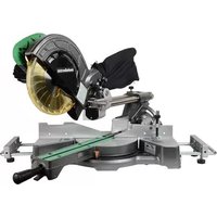
Read the operating instructions. Never place hands into running saw blade. Wear protective goggles and ear protectors. Never operate the tool in a damp or wet environment. Laser radiation - Do not look into the light beam. LASER CLASS 2 Do not direct the light beam into the eyes of people or animals. Information on the nameplate: (a)Manufacturer (b)Serial number (c)Device designation (d)Motor data (see also "Technical data") (e)CE mark – This device fulfils the EU directives according to the declaration of conformity (f) Recycling symbol – Device can be recycled via the manufacturer (g)Year of manufacture (h)Dimensions of approved blades See page 2 - 3. 1 Chip extraction nozzle 2 Chip bag 3Closing the chip bag 4 Allen key / tool storage for Allen key 5 Riving knife 6Blade guard 7 Parallel stop 8Safety lock 9 Saw handle 10 Saw's off button 11 Saw's on button 12 Side protection 13 Upper table 14 Locking button for blade locking 15 Set screws (for adjusting the upper table) 16 On/off switch cutting laser 17 On/off switch cutting line illumination 18 Transport lock (bolts) 19 Transport lock (hooks) 20 Cable winder 21 Cutting line illumination 22 Workpiece clamp 23 Adjustable guide 24 Set screw (of the guide) 25 Laser beam egress point 26 Retractable blade guard 27 Parallel guide/ ripping fence (both sides) 28 Longitudinal guide (foldable) 29 Table extension 30 Locking screw of the table width extension 31 Safety catch for stop positions of the turntable 32 Locking handle (turntable) 33 Table insert 34 Turntable 35 Table 36 Carry handles 37 Screws on the guide rails of the table extension 38 Set angle of inclination 39 Locking lever for setting the angle of inclination 40 Locking button (to extend the angle of inclination by +/- 2 °) 41 Push stick 42 Push stick holder 43 Workpiece clamp: rear drill hole 44 Workpiece clamp: front drill hole 45 Clamping bolt with washer 46 Outer flange 47 Saw blade 48 Direction-of-rotation arrow on the saw blade cover 49 Inner flange 50 Saw blade shaft 51 Adjust workpiece limit stop: Allen key 52 Sawing a curved (warped) plank
Caution! Do not carry the saw bay the protective equipment. Do not carry by the saw handle (9). To carry, hold on the two sides under the lower table. Lift device up out of the packaging with help from a second person.
from the transport packaging.
2. Remove screws (37) at the guide rails of the
extensions completely into the recesses. Insert the table width extension with folding length guide (28) on the right side.
4. Lift the device at the front legs, carefully swivel
it backwards and put it down so it will not fall over.
5. Tighten again the screws (37) at the guide
6. Take the front legs of the device, carefully
swivel it forwards and put down.
7. Set the desired table width and lock the table
width extensions with locking screws (30).
6.3 Attaching the additional handle
The machine is supplied with a laser warning label in German. Before using the machine, cover this label with the relevant enclosed laser warning label in your national language.
The device has to be mounted on a stable support for safe working. – The support can be either a firmly mounted work top or work bench. – Even when machining larger workpieces the device has to have a secure stand. – Before each cutting process, ensure that the machine is standing securely. – Long workpieces must get additional support with suitable accessories. Note: For mobile use, the device can also be fixed to a plywood or coreboard panel (500 mm x 500 mm, at least 19 mm thick) using screws. During use, the panel has to be fixed to a work bench using screw clamps.
6. Unpacking, assembly,
installation and transportENGLISHen
1. Fix device to the support using screws.
2. Unhook transport lock (19).
3. Loosen transport lock (18): Press saw head
and saw handle (9) down slightly and hold. Pull out transport lock (18).
4. Swivel saw head slightly upwards.
Caution! Do not hold the saw at the protective installations during transport. Do not carry by the saw handle (9). For transport, the blade must be covered by the blade guard (6). Danger! Switch off device, unplug, wait until the device has come to a stop.
1. Rotate turntable to the 0° position, tighten the
locking handle (22) for turntable (see chapter 7.5).
2. Set angle of the swivel arm to the vertical at 0°,
tighten locking lever (39) for angle adjustment (see chapter 7.4).
3. If the saw head is raised, place the side
protection (12) from the left on the table insert (33) and push down. Check it fits firmly.
4. Press safety lock (8) and lower the saw head
on the saw handle (9) all the way down
5. Hook transport lock (19).
6. Push transport lock (18) all the way in.
7. Loosen locking screws (30), push table
extensions (29) all the way in and lock with locking screws (30).
8. Lift and carry device on both sides using carry
7.1 On/off switch of the saw
Switch on motor: Press on button (11). Switch off motor: Press off button (10).
7.2 On/off switch cutting line
illumination (17) (When used as chop and mitre saw) Switching on/ off the illumination of the cutting line. Danger! Do not direct the light beam into the eyes of people or animals.
7.3 On/off switch cutting laser (16)
(When used as chop and mitre saw) Switching on/off of the cutting laser. The cutting laser marks a line to the left of the saw's cut. Make a trial cut to become familiar with the positioning. Danger! LASER BEAM
7.4 Setting the angle of inclination
(When used as chop and mitre saw) After loosening the locking lever (39), the saw can be infinitely inclined between 0° and 45° to the left of the vertical position (38). Press the locking button (40) during the adjustment process in order to also set angles up to 47° to the left of the vertical/ up to 2° to the right of the vertical. Danger! In order for the angle of inclination not to change when cutting, the locking lever (39) of the swivel arm has to be tightened.
(When used as chop and mitre saw) After loosening the locking handle (32) and activating the safety catch (31), the turntable can be turned by 52° to the left or by 52° to the right for mitre cuts. In this manner the cutting angle to the support edge of the workpiece is adjusted. If the safety catch (31) is raised, the turntable ratchets to the angles 0°, 15°, 22.5°, 31.6° and 45°. If the safety catch (31) is pushed downwards all the way, the locking function is deactivated. Danger! In order for the mitre angle not to change during cutting, the locking handle (32) of the turntable has to be tightened (also in the stop positions!).
(When used as chop and mitre saw) The parallel guide/ ripping fence (27) supports the workpiece on both sides of the saw cut. The parallel guide/ ripping fence (27) prevents that the workpiece can be moved during the cutting process. During operation, the parallel guide/ ripping fence always has to be installed. The adjustable guide (23) at the parallel guide/ ripping fence has to be moved for inclined cuts after loosening the set screw (24). Ensure that the adjustable stop (23) has been adjusted correctly and that the workpiece is supported as well as possible without touching the blade or retractable blade guard. Lock using the set screw (24).
(When used as table saw) The ripping fence (7) is mounted on the upper table (13). The locking screw must face forwards. The ripping fence can be removed and changed after the locking screw has been loosened.
(When used as table saw) The height of the upper table (13) can be adjusted in order to change the cutting depth.
8.1 Connect chip sack / chip and dust
extraction unit Danger! Dust of certain timber species (e.g. beech, oak, ash) can cause cancer when inhaled. – Only use a suitable dust extraction unit or installed dust sack. – In addition, use a dust mask, as not all saw dust is collected or extracted. – Regularly empty the dust sack. Wear a dust mask while emptying the sack. If you operate the device with the supplied dust sack: Attach the dust sack (2) to the chip extraction adapter nozzle (1). Ensure that the closure (3) of the dust sack is closed. If you connect the device to a dust extraction unit: Use a suitable adapter to connect it to the chip extraction adapter nozzle (see chapter 13. "Accessories"). Ensure that the dust extraction unit meets the requirements stated in chapter 17. "Technical Specifications". Observe the dust collector's operating instructions as well!
8.2 Installing the workpiece clamping
device (When used as chop and mitre saw) The workpiece clamping device (22) can be installed in two positions: –For wide workpieces: Insert the workpiece clamping device into the rear drilling (43) of the table. – For narrow workpieces: Insert the workpiece clamping device into the front drilling (44) of the table.
8.3 Power-supply connection
Danger! High voltage Operate machine only on a power source meeting the following requirements (see also chapter 17. "Technical Specifications"): – Mains voltage and system frequency must conform to the voltage and frequency shown on the machine´s rating label; – fuse protection by a residual current operated device (RCD) of 30 mA sensitivity; – outlets properly installed, earthed or grounded, and tested. Position power supply cable so it does not interfere with the work and is not damaged. Use only rubber-jacketed extension cables with sufficient lead cross-section (3 × 1.5 mm
Use extension cables for outdoor areas. When working outdoors, only use the correspondingly marked extension cable approved for this purpose.
Avoid accidental start-up. Ensure that the on/off switch is switched off when inserting the plug in the socket.
Operate the device in dry surroundings only.
Protect power supply cable from heat, aggressive liquids and sharp edges.
Do not pull on power supply cable to unplug.
Retractable blade guard (26) The retractable blade guard protects against unintentional contact with the saw blade and from chips flying about. The retractable blade guard must always return to its initial position automatically: If the saw head is raised, the blade must be covered all round. Safety lock (8) The retractable blade guard opens and the saw can be lowered only when the safety lock is activated. Parallel guide/ ripping fence (27) The parallel guide/ ripping fence (27) supports the workpiece on both sides of the saw cut. The parallel guide/ ripping fence (27) prevents that the workpiece can be moved during the cutting process. During operation, the parallel guide/ ripping fence always has to be installed. The adjustable guide (23) at the parallel guide/ ripping fence has to be moved for inclined cuts after loosening the set screw (24). Ensure that the adjustable stop (23) has been adjusted correctly and that the workpiece is supported as well as possible without touching the blade or retractable blade guard. Lock using the set screw (24).
Danger! Before setting up the device: Switch off device, unplug, wait until the device has come to a stop. Danger of crushing! When adjusting the height of the upper table (13), do not hold the area between the upper table and saw head! Danger! When loosening the locking screws (15) the upper table (13) may suddenly move up. Hold the upper table tight with one hand.
1. Loosen both locking screws (15). The upper
table (13) is pushed up by spring force or move the upper table to its uppermost position. Retighten both locking screws (15).
7. The device in detail
9. Operation / Use as chop and
3. Loosen transport lock (18): Press saw head
and saw handle (9) down slightly and hold. Pull out transport lock (18).
4. Swivel saw head slightly upwards.
5. If the saw head is raised, remove the side
place (12) and place to one side. Before starting work, check to see that the following are in proper working order. Before working, check that the upper part of the blade is fully enclosed or covered. Assume proper operating position: – at the front of the saw; – in front of the saw; – next to the line of cut. Danger! Always fasten the workpiece with the workpiece clamping device (22). It is held safer by these devices than by your hand. Danger of crushing! When inclining or swivelling the saw head, never reach into the hinge area or below the device! Hold the saw head during inclination. Use during work: – Workpiece support – for long workpieces if it would fall from the table after cutting. – Dust sack or dust extraction unit. – Personal safety equipment Cut only workpieces of dimensions that allow for safe and secure holding while cutting. Always hold the workpiece down on the table and do not jam it. Do not attempt to stop the saw blade by pushing the workpiece against its side. Risk of personal injury if the saw blade is blocked.
Starting position: –Transport lock (18) pulled out. – Saw head swivelled upwards. –Turntable is in 0° position, locking handle (32) for turntable is tightened (see chapter 7.5). – The inclination of the swivel arm to the vertical is 0°, locking lever (39) for inclined position is tightened see chapter 7.4). – Adjust and lock the adjustable guide (23) (see
Cutting the workpiece:
1. Push the workpiece against the parallel guide
(27) and clamp using the workpiece clamping device (22).
4. Slowly lower the saw head on the saw handle
(9) all the way down. During the sawing process press on the workpiece just enough for the motor speed not to lower too much.
5. Cut the workpiece in one operation.
6. Slowly return the saw head to the upper
Starting position: –Transport lock (18) pulled out. – Saw head swivelled upwards. – The inclination of the swivel arm to the vertical is 0°, locking lever (39) for inclined position is tightened see chapter 7.4). – Adjust and lock the adjustable guide (23) (see
Cutting the workpiece:
1. Loosen locking handle (32) of the turntable
and loosen safety catch (31).
2. Set the desired angle (see chapter 7.5).
3. Tighten the locking handle (32) of the
4. Cut workpiece, as described for "Straight
Starting position: –Transport lock (18) pulled out. –Saw head swivelled upwards. – Turntable is in 0° position, locking handle (32) for turntable is tightened (see chapter 7.5). – Adjust and lock the adjustable guide (23) (see
Cutting the workpiece:
1. Loosen the locking lever (39) for the
inclination setting at the rear side of the saw.
2. Slowly turn the swivel arm into the desired
position (see chapter 7.4).
3. Tighten the locking lever (39) for the
inclination setting.
4. Cut the workpiece, as described in "Straight
Note: The double mitre cut is a combination of mitre cut and inclined cut. This means, the workpiece is cut at an angle to the rear contact edge and at an angle to the top. Danger! With a double mitre cut, the saw blade is easier accessible due to the steep inclination – this results in a higher risk of injury. Always keep sufficient distance to the saw blade! Starting position: –Transport lock (18) pulled out. –Saw head swivelled upwards. – Lock the turn table in the desired position. (see
– Swivel arm inclined at desired angle to the workpiece surface and locked. (see
– Adjust and lock the adjustable guide (23) (see
Cutting the workpiece: Cut the workpiece, as described in "Straight cuts".
Blade guard The blade guard (6) protects against inadvertent touching of the blade and against flying shavings. Always have blade guard installed during operation. Splitting wedge The splitting wedge (5) prevents a workpiece from being caught by the rising teeth and being thrown against the operator. Always have the splitting wedge installed during operation. Side protection The side protection (12) protects against inadvertent contact with the blade. The side protection must always be fitted correctly during use. Only then can the table saw be used. Push stick The push stick (41) serves as an extension of the hand and protects against inadvertent contact with the blade. Always use push stick if distance between saw blade and ripping fence is less than 120 mm. The push stick must be held at angle of 20° … 30° to the surface of the saw table. Replace push stick if damaged. Fasten the push stick in its holder (42) when not in use.
Danger! Before setting up the device: Switch off device, unplug, wait until the device has come to a stop.
1. Rotate turntable to the 0° position, tighten the
locking handle (22) for turntable (see chapter 7.5).
2. Set angle of the swivel arm to the vertical at 0°,
tighten locking lever (39) for angle adjustment (see chapter 7.4).
3. If the saw head is raised, place the side
protection (12) from the left on the table insert (33) and push down. Check it fits firmly.
4. Press safety lock (8) and lower the saw head
on the saw handle (9) all the way down
5. Hook transport lock (19).
6. Push transport lock (18) all the way in.
Danger of crushing! When adjusting the height of the upper table (13), do not hold the area between the upper table and saw head! Danger! When loosening the locking screws (15) the upper table (13) may suddenly move up. Hold the upper table tight with one hand.
7. Loosen both locking screws (15). The upper
table (13) is pushed up by spring force. Danger! Body parts or objects in the adjustment area can get caught by the running saw blade! Set depth of cut only with saw blade at standstill! The saw blade's cutting depth needs to be adapted to the workpiece’s height: the blade guard shall rest with its front edge on the workpiece.
8. Adjust the cutting depth by pressing the upper
table down. Retighten both locking screws (15) firmly.
9. Ensure that the upper table is securely
fastened with locking screws (15). Before starting work, check to see that the following are in proper working order: – Splitting wedge – Side protection; –Blade guard – Feed aids (push stick or push rod and handle). Ensure the machine's stand is stable. Assume proper operating position: – at the front of the saw; – in front of the saw; – to the left of the line of cut; – when working with two persons, the other person must remain at an adequate distance to the saw. Use during work: – Workpiece support – for long workpieces if it would fall from the table after cutting. – Dust sack or dust extraction unit. – Personal safety equipment Cut only workpieces of dimensions that allow for safe and secure holding while cutting. Always hold the workpiece down on the table and do not jam it. Do not attempt to stop the saw blade by pushing the workpiece against its side. Risk of personal injury if the saw blade is blocked.
Danger! Always use push stick if distance between saw blade and rip fence is less than 120 mm.
1. Set depth of cut. The blade guard must rest
with its front edge on the workpiece.
10. Operation / Use as table sawENGLISHen
2. If necessary, fit ripping fence, locking screw
3. Set cutting width with ripping fence.
5. Push the workpiece in a steady motion
towards the rear and cut in a single pass.
6. Switch the machine off if no further cutting is to
be done immediately afterwards. Danger! Disconnect the mains plug before starting any setting, maintenance or repair work. Disconnect from the mains power before any maintenance or cleaning work. – Repair and maintenance work other than described in this section should only be carried out by qualified specialists. – Replace damaged parts, in particular safety installations, only with original parts. Parts not approved by the equipment manufacturer can cause unforeseeable damage. – Check that all safety devices are operational again after each service.
11.1 Saw blade change
Risk of burning! Directly after cutting the saw blade can be very hot. Let a hot saw blade cool down. Do not clean the hot saw blade with combustible liquids. Risk of injury, even with the blade at standstill! When loosening and tightening the tensioning screw (45) the retractable blade guard (26) has to be swivelled over the saw blade. Wear gloves when changing blades.
1. Disconnect the mains plug. (see chapter 9.2).
2. Put the saw head in the upper position.
3. Lock saw blade: press the locking button (14)
and turn the saw blade with the other hand until the locking button (14) engages. Hold down the locking button (14).
4. Remove the tensioning screw with washer
(45) on the saw blade shaft with Allen key (4) in clockwise direction (left-hand thread!).
5. Loosen safety lock (8) and push the
retractable blade guard (26) upwards and hold.
6. Carefully remove outer flange (46) and saw
blade (47) from the saw blade shaft and close again the retractable blade guard. Danger! Do not use cleaning agents (e.g. to remove resin residue) that could corrode the light metal components of the saw; the stability of the saw would be adversely affected.
7. Cleaning the clamping surfaces:
– Saw blade shaft (50), – saw blade (47), –outer flange (46), –inner flange (49). Danger! Place inner flange properly! If this is not the case, the saw can block or the saw blade could work loose. The inner flange is in the correct position if the ring groove points towards the saw blade and the flat side to the motor.
8. Put on inner flange (49).
9. Loosen safety lock (8) and push the
retractable blade guard (26) upwards and hold. 10.Place a new saw blade - pay attention to direction of rotation: Seen from the left (open) side, the arrow on the saw blade has to correspond to the direction of the arrow (48) on the saw blade cover! Danger! Use only saw blades, which fulfil the requirements and specifications listed in these operating instructions. Only use suitable blades, which are designed for the maximum speed (see "Technical data") – is unsuitable, damaged or defined blades are used, parts may be thrown out as a result of the centrifugal force. Saw blades intended for cutting wood or similar materials have to conform to EN 847-1. Do not use: – saw blades made of high-alloy speed steel (HSS); – damaged or deformed blades; – cut-off wheel blades. – Blades with a cutting width less than the thickness of the splitting wedge or a main blade width greater than the thickness of the splitting wedge. Danger! – Mount saw blade using only genuine parts. – Do not use loose-fitting reducing rings; the saw blade could work loose. – Saw blades have to be mounted in such way that they do not wobble or run out of balance and cannot work loose during operation. 11.Close again retractable blade guard (26). 12.Slide on outer flange (46) – The flat side has to point towards the motor! 13.Put on the tensioning screw with the washer (45) in anti-clockwise direction (left-hand thread) and tighten by hand. 14.Lock saw blade: press the locking button (14) and turn the saw blade with the other hand until the locking button engages. Hold down the locking button. Danger! – Do not extend the hexagon wrench. – Do not tighten the tensioning screw by hitting the hexagon wrench. 15.Firmly tighten the tensioning screw (45) using the hexagon wrench (4). 16.Check function. Loosen the safety lock (8) and fold the saw downwards: – when folding down the retractable blade guard, it has to provide free access to the saw blade without touching other parts. – When folding the saw upwards into the starting position, the retractable blade guard has to cover the saw blade automatically. – Rotate the saw blade manually. You should be able to rotate the saw blade into any possible position without touching other parts.
11.2 Table insert change
Danger! With a damaged table insert (33) there is a risk of small parts getting stuck between table insert and saw blade, blocking the saw blade. Replace damaged table inserts immediately!
1. Remove screws at table insert. If required,
rotate turntable and incline saw head to be able to reach the screws.
11.3 Adjust parallel guide/ripping fence
1. Loosen Allen screws (51).
2. Adjust the parallel guide/ripping fence (27) in
such a way that it is exactly perpendicular to the saw blade when the turntable engages in the 0° position.
3. Tighten the Allen screws (51).
11.4 Cleaning the device
Remove chips and saw dust with vacuum cleaner or brush from: – adjustment installations – controls; – motor vent slots; –space under table insert; – cutting laser; – Cutting line illumination
11.5 Storage of device
Danger! Store the device in such a way that it cannot be put into operation by unauthorised personnel. Ensure that the stationary device cannot cause injury. Caution! Do not store the tool outdoors or in damp conditions without protection. Observe permissible ambient conditions (see
Prior to each use Remove saw chips with vacuum or brush. Check power cable and power cable plug for damage; if necessary have damaged parts replaced by a qualified electrician. Check all movable parts if they can be moved freely across the entire range of movement. Always work with a properly set splitting wedge. Check whether the riving knife – blade distance is between 3 mm and 8 mm. If necessary, repair before using the device. Check whether the retractable blade cover (26) works properly and does not stick. It has to provide free access to the saw blade without touching other parts. When folding the saw upwards into the starting position, it has to cover the saw blade automatically. If parts are damaged or not working correctly, have the device repaired before using. Check the table insert (33). A damaged table insert must be replaced immediately. Check whether the protective equipment is in the envisaged position, particularly after a refitting a table saw to a chop and mitre saw. If parts are damaged or not working correctly, have the device repaired before using. Regularly, depending on conditions of use Regularly check the power cable on the power tool and have repaired by an approved expert if damaged. Regularly check extension cables and replace if damaged. Check all screwed joints, retighten if necessary. Check reset function of the saw head (saw head has to return to the upper starting position by means of spring force), if required have spring replaced. Slightly oil guide elements. – Use appropriate supports on the left and right of the saw for long workpieces. – Hold workpiece on the right of the saw blade for suitable cuts. – When cutting small pieces, use additional guide (a suitable wooden board attached with screws to the guide of the device, can be used as additional guide). – When cutting a curved (contorted) board (52) place the convex side at the parallel guide/ ripping fence. – Do not cut workpiece upright, but flat on the turntable. – Keep surfaces of the supporting tables clean – in particular remove resin residue with an appropriate cleaning and care spare.
Use only genuine Metabo accessories. Use only accessories that fulfil the requirements and specifications listed in these operating instructions. CAUTION! The use of other tools and accessories can result in a risk of injury. A Spray for maintenance and care for the removal of resin residues and to preserve the metal surfaces. 0911018691 B Extraction adapter "Multi" for the connection of extraction hoses with 44, 58 or 100 mm adapter
C Metabo all-purpose vacuum cleaner (see catalogue) D Stands: Universal machine stand UMS: 6.31317 Machine stand KSU 251: 6.29005 Machine stand KSU 401: 6.29006 E Roller stand: RS 420 0910053353 F Saw blade Precision Cut Classic 6.28064 305 × 30 x 2.4 /1.8,56 WZ 5° neg for longitudinal and transverse cuts in solid wood and chipboard G Sägeblatt Precision Cut 6.28227 305 x 30 x 2,4/1,8 48 WZ 5° neg for efficient longitudinal and transverse cuts in solid wood and chipboard H Saw blade Multi Cut 6.28091 305 x 30 x 2.8/2.0 96 FZ/TZ 5° neg, for longitudinal and transverse cuts in coated materials, laminate, plastic and aluminium profiles For a complete range of accessories, see www.metabo.com or the catalogue. Danger! Repair of power tools must be carried out by qualified electricians only! This power tool complies with the applicable safety regulations. Repairs must only be carried out by qualified electricians and using original spare parts; otherwise the user faces a risk of accidents. If you have Metabo power tools that require repairs, please contact your Metabo service centre. See www.metabo.com for addresses. Do not replace cutting area lighting (17) and cutting laser (16) with another type. A defective mains cable must only be replaced with a special, original mains cable from metabo, which is available only from the Metabo service. You can download a list of spare parts from www.metabo.com. Observe national regulations on environmentally compatible disposal and on the recycling of disused machines, packaging and accessories. Only for EU countries: never dispose of power tools in your household waste! Used power tools must be collected separately and handed in for environmentally compatible recycling in accordance with European Directive 2012/19/EU on waste electrical and electronic equipment and its implementation in national legal systems. Following you will find a description of problems and faults that you may remedy yourself. If the corrective measures described here do not help, kindly refer to chapter 14. "Repairs". Danger! There are particularly many accidents in connection with problems and faults. Therefore keep in mind: Disconnect the mains plug prior to any fault service. Check that all safety devices are operational again after each fault service. Motor does not run No mains voltage: Check cables, plug, outlet and mains fuse. No trimming function Transport lock (18) locked: Pull out transport lock (18). Transport lock (19) locked: Unhook transport lock (19). Safety lock (8) locked: Press safety lock (8) Cutting power too low Saw blade blunt (possibly tempering marks on blade body); Saw blade unsuitable for the material (see
chapter 13. "Accessories");
Saw blade contorted: Replace saw blade (see chapter 11. "Maintenance"). Saw vibrates a lot Saw blade contorted: Replace saw blade (see chapter 11. "Maintenance"). Saw blade not installed properly: Install saw blade properly (see chapter 11. "Maintenance"). Turntable hard to turn Chips under turntable: Remove chips. Upper table (13) cannot be lowered when used as a table saw Fit side protection (12) correctly. Explanatory notes on the specifications on page 4. Subject to change in accordance with technical progress. U=mains voltage I=Rated power F =min. fuse protection
=rated input power IP =protection class
=Max. cutting speed D=largest / smallest blade diameter (outer) d = saw blade hole (inside) b = max. tooth width of the saw blade c = thickness of the splitting wedge A =dimensions (lxwxh) m=weight T =Ambient temperature range Requirements for chip and dust extraction unit:
=connection diameter of the extraction nozzle
=minimum air throughput
=minimum negative pressure at extraction nozzle
=minimum air speed at extraction nozzle H = cutting depth when used as a table saw Maximum cross-section of the workpiece when used as a chop and mitre saw, see table on page 4. ~ AC Power Machine in protection class II The technical specifications quoted are subject to tolerances (in compliance with the relevant valid standards). Emission values These values make it possible to assess the emissions from the power tool and to compare different power tools. The actual load may be higher or lower depending on the operating conditions, the condition of the power tool or the accessories. Please allow for breaks and periods for assessment purposes when the load is lower. Arrange protective measures for the user, such as organisational measures based on the adjusted estimates. Vibration total value (vector sum of three directions) determined in accordance with EN 61029:
=vibration emission value
= Uncertainty (vibration) Typical A-effective perceived sound levels
=sound-pressure level
=acoustic power level
= uncertainty Wear ear protectors!