DVC665ZU - Cordless vacuum MAKITA - Free user manual and instructions
Find the device manual for free DVC665ZU MAKITA in PDF.
| Product Type | Cordless Vacuum Cleaner |
| Brand | Makita |
| Model | DVC665ZU |
| Dimensions (without harness) | 297 mm x 174 mm x 523 mm (L x W x H) |
| Net weight (with battery) | 6.1 - 6.7 kg |
| Power Supply | Lithium-ion battery 36 V DC (compatible BL1815N/BL1820B/BL1830B/BL1840B/BL1850B/BL1860B) |
| Filter bag capacity | 6.0 L |
| Dust bag capacity | 5.5 L |
| Maximum air volume | 1.8 m³/min (with hose ø28 mm x 1.5 m) |
| Maximum vacuum | 110 hPa |
| Suction power | 2 levels: normal (1) and high (2) |
| Wireless activation function | Yes, automatic start/stop with compatible Makita tool |
| Dust shaking system | Yes, integrated mechanism to maintain suction power |
| Battery protection | Overload, overheating, complete discharge |
| Filter | Washable HEPA filter with water |
| Sound pressure level | 70 dB(A) or less (uncertainty K=2.5 dB(A)) |
| Vibration (no-load operation) | ≤2.5 m/s² (uncertainty K=1.5 m/s²) |
| Use | Indoor, non-hazardous dry dust |
| Maintenance | Regular cleaning of HEPA filter and dust bag |
| Safety | Automatic shutdown in case of overload, overheating, or low battery |
| Included accessories | Hose, bent tube, front sleeve (depending on country) |
| Warranty | Makita manufacturer warranty (see terms) |
Frequently Asked Questions - DVC665ZU MAKITA
User questions about DVC665ZU MAKITA
0 question about this device. Answer the ones you know or ask your own.
Ask a new question about this device
Download the instructions for your Cordless vacuum in PDF format for free! Find your manual DVC665ZU - MAKITA and take your electronic device back in hand. On this page are published all the documents necessary for the use of your device. DVC665ZU by MAKITA.
USER MANUAL DVC665ZU MAKITA
natural_image
Line drawing of a portable air purifier device with attached cable and control panel (no text or symbols)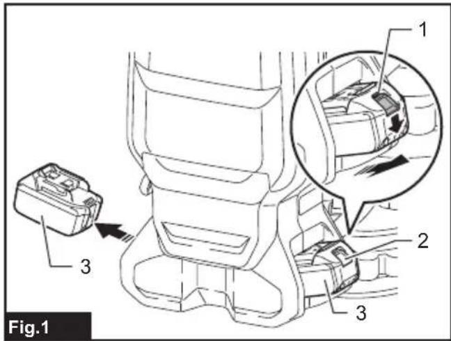
natural_image
Technical line drawing of a mechanical component with labeled part '1' (no text or symbols beyond label)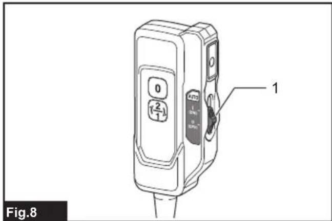

natural_image
Line drawing of a diver in full-body medical equipment with hoses and straps (no text or symbols)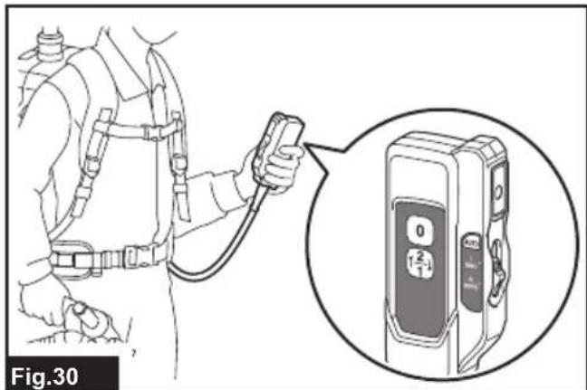
natural_image
Illustration of a person using a handheld device to connect equipment, with an inset showing a close-up of the device (no text or symbols visible)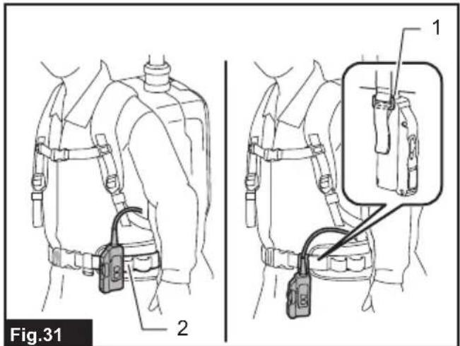
natural_image
Diagram showing a mechanical component before and after processing, with no visible text or symbols.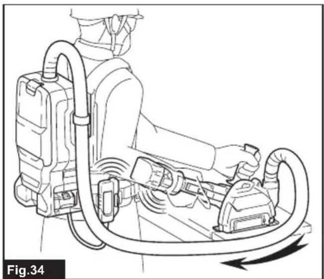
natural_image
Line drawing of a person operating a portable air purifier device with hoses and control panel (no text or symbols)
natural_image
Line drawing of a person using a harness and tool, with an arrow indicating motion direction (no text or symbols)Fig.37

natural_image
Line drawing of a container pouring liquid into a basin (no text or symbols)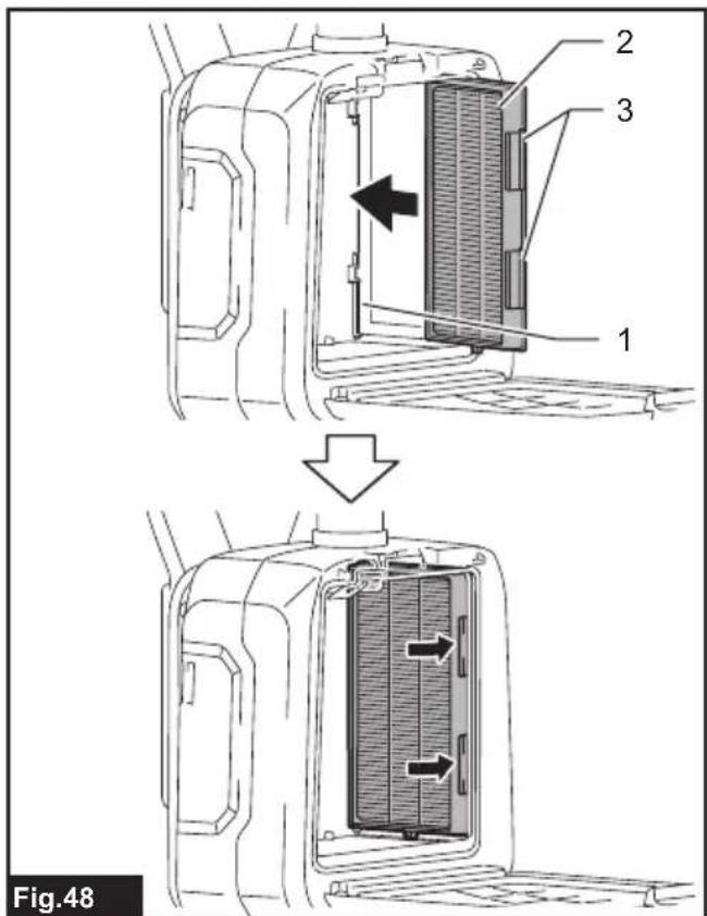
flowchart
graph TD
    A["Step 1: Assembly of the door panel"] --> B["Step 2: Tool insertion and disassembly"]
    B --> C["Step 3: Disassembly of the door panel"]
    C --> D["Step 4: Assembly of the door panel with a screwdriver"]
natural_image
Illustration of a handheld device with a hand operating it, showing a close-up of its internal components (no text or symbols present)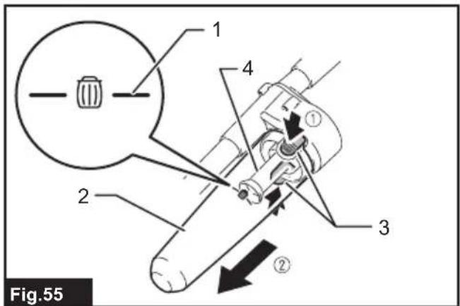
WARNING
- This machine is not intended for use by persons including children with reduced physical, sensory or mental capabilities, or lack of experience and knowledge.
- Children should be supervised to ensure that they do not play with the cleaner.
- See the chapter "SPECIFICATIONS" for the type reference of the battery.
- See the section "Installing or removing battery cartridge" for how to remove or install the battery.
- When disposing the battery cartridge, remove it from the tool and dispose of it in a safe place. Follow your local regulations relating to disposal of battery.
- If the tool is not used for a long period of time, the battery must be removed from the tool.
- Do not short the battery cartridge.
- See the chapter "MAINTENANCE" for the appropriate details of precautions during user maintenance.
SPECIFICATIONS
| Model: DVC665 | ||
| Capacity Filter bag 6.0 L | ||
| Dust bag 5.5 L | ||
| Maximum air volume(With hose ø28 mm x 1.5 m) | 1.8 m^3/min | |
| Vacuum 110 hPa | ||
| Dimensions (L x W x H)(excluding the harness) | 297 mm x 174 mm x 523 mm | |
| Rated voltage D.C. 36 V | ||
| Net weight 6.1 - 6.7 kg | ||
- Due to our continuing program of research and development, the specifications herein are subject to change without notice.
• Specifications may differ from country to country. - The weight does not include accessories but battery cartridge(s). The lightest and heaviest combination weight of the appliance and battery cartridge(s) are shown in the table.
Applicable battery cartridge and charger
| Battery cartridge BL1815N / BL1820B / BL1830B / BL1840B / BL1850B / BL1860B |
| Charger DC18RC / DC18RD / DC18RE / DC18SD / DC18SE / DC18SF /DC18SH |
- Some of the battery cartridges and chargers listed above may not be available depending on your region of residence.

WARNING: Only use the battery cartridges and chargers listed above. Use of any other battery cartridges, I chargers may cause injury and/or fire.

WARNING: Do not use a corded power supply such as battery adapter or portable power pack with its tool. Wearing more than one harness at a time makes it difficult to operate and release the tool, and may use an injury.
Symbols
The followings show the symbols which may be used for the equipment. Be sure that you understand their meaning before use.

Read instruction manual.

Take particular care and attention.
Only for EU countries
Due to the presence of hazardous components in the equipment, waste electrical and electronic equipment, accumulators and batteries may have a negative impact on the environment and human health. Do not dispose of electrical and electronic appliances or batteries with household waste!
In accordance with the European Directive on waste electrical and electronic equipment and on accumulators and batteries and waste accumulators and batteries, as well as their adaptation to national law, waste electrical equipment, batteries and accumulators should be stored separately and delivered to a separate collection point for municipal waste, operating in accordance with the regulations on environmental protection.
This is indicated by the symbol of the crossed-out wheeled bin placed on the equipment.
Intended use
The appliance is intended for collecting dry dust. The appliance is suitable for commercial use, for example in hotels, schools, hospitals, factories, shops, offices and rental businesses.
Noise
The typical A-weighted noise level determined according to IEC60335-2-69, IEC60704-2-1:
Sound pressure level ( L_pA ): 70 dB(A) or less
Uncertainty (K) : 2.5 dB(A)
The noise level under working may exceed 80 dB (A).
NOTE: The declared noise emission value(s) has been measured in accordance with a standard test method and may be used for comparing one tool with another.
NOTE: The declared noise emission value(s) may also be used in a preliminary assessment of exposure.

WARNING: Wear ear protection.

WARNING: The noise emission during actual time of the power tool can differ from the declared value(s) depending on the ways in which the value is used especially what kind of workpiece is accessed.

WARNING: Be sure to identify safety measures to protect the operator that are based on animation of exposure in the actual conditions of the (taking account of all parts of the operating cycle such as the times when the tool is switched and when it is running idle in addition to the longer time).
Vibration
The vibration total value (tri-axial vector sum) determined according to IEC60335-2-69:
Work mode: operation without load
Vibration emission (ah): 2.5 m/s ^2 or less
Uncertainty (K) : 1.5 m/s
NOTE: The declared vibration total value(s) has been measured in accordance with a standard test method and may be used for comparing one tool with another.
NOTE: The declared vibration total value(s) may also be used in a preliminary assessment of exposure.

WARNING: The vibration emission during actual use of the power tool can differ from the declared value(s) depending on the ways in which the tool is used especially what kind of workpiece processed.

WARNING: Be sure to identify safety measures to protect the operator that are based on an estimation of exposure in the actual conditions of the (taking account of all parts of the operating cycle such as the times when the tool is switched and when it is running idle in addition to the bigger time).
EC Declaration of Conformity
For European countries only
The EC declaration of conformity is included as Annex A to this instruction manual.
SAFETY WARNINGS
Cordless vacuum cleaner safety warnings

WARNING: IMPORTANT! READ CAREFULLY safety warnings and all instructions BEFORE E. Failure to follow the warnings and instructions y result in electric shock, fire and/or serious injury
- Before use, make sure that this cleaner must
be used by people who have been adequately instructed on the use of this cleaner. - Do not use the cleaner without the filter. Replace a damaged filter immediately.
- Do not attempt to pick up flammable materials, fire works, lighted cigarettes, hot ashes, hot metal chips, sharp materials such as razors, needles, broken glass or the like.
- NEVER USE THE CLEANER IN THE VICINITY OF GASOLINE, GAS, PAINT, ADHESIVES OR OTHER HIGHLY EXPLOSIVE SUBSTANCES. The switch emits sparks when turned ON and OFF. And so does the motor commutator during operation. A dangerous explosion may result.
- This cleaner is not suitable for picking up hazardous dust.
- Never vacuum up toxic, carcinogenic, combustible or other hazardous materials such as asbestos, arsenic, barium, beryllium, lead, pesticides, or other health endangering materials.
-
Never use the cleaner outdoors in the rain.
-
For Finland, this machine is not to be used outdoors at low temperature.
- Do not use close to heat sources (stoves, etc.).
- Do not block cooling vents. These vents permit cooling of the motor. Blockage should be carefully avoided otherwise the motor will burn out from lack of ventilation.
- Keep proper footing and balance at all times.
- Do not fold, tug or step on the hose.
- Stop the cleaner immediately if you notice poor performance or anything abnormal during operation.
- DISCONNECT THE BATTERIES. When not in use, before servicing, and when changing accessories.
- Clean and service the cleaner immediately after each use to keep it in tiptop operating condition.
- MAINTAIN THE CLEANER WITH CARE. Keep the cleaner clean for better and safer performance. Follow instructions for changing accessories. Keep handles dry, clean, and free from oil and grease.
- CHECK DAMAGED PARTS. Before further use of the cleaner, a guard or other part that is damaged should be carefully checked to determine that it will operate properly and perform its intended function. Check for alignment of moving parts, binding of moving parts, breakage of parts, mounting, and any other conditions that may affect its operation. A guard or other part that is damaged should be properly repaired or replaced by an authorized service center unless otherwise indicated elsewhere in this instruction manual. Have defective switches replaced by authorized service center. Don't use the cleaner if switch does not turn it on and off.
- REPLACEMENT PARTS. When servicing, use only identical replacement parts.
- When not in use, always store the cleaner indoors.
- Be kind to your cleaner. Rough handling can cause breakage of even the most sturdily built cleaner.
- Do not attempt to clean the exterior or interior with benzine, thinner or cleaning chemicals. Cracks and discoloration may be caused.
- Do not use cleaner in an enclosed space where flammable, explosive or toxic vapors are given off by oil-base paint, paint-thinner, gasoline, some mothproofing substances, etc., or in areas where flammable dust is present.
- Do not operate the cleaner while under the influence of drugs or alcohol.
- As a basic rule of safety, use safety goggles or safety glasses with side shields.
- Use a dust mask in dusty work conditions.
- This machine is not intended for use by persons including children with reduced physical, sensory or mental capabilities, or lack of experience and knowledge.
-
Children should be supervised to ensure that they do not play with the cleaner.
-
Never handle battery(ies) and cleaner with wet hands.
- Use extreme caution when cleaning on stairs.
- Do not use the cleaner as a stool or work bench. The machine may fall down and may result in personal injury.
Battery tool use and care
-
Recharge only with the charger specified by the manufacturer. A charger that is suitable for one type of battery pack may create a risk of fire when used with another battery pack.
-
Use power tools only with specifically designated battery packs. Use of any other battery packs may create a risk of injury and fire.
-
When battery pack is not in use, keep it away from other metal objects, like paper clips, coins, keys, nails, screws or other small metal objects, that can make a connection from one terminal to another. Shorting the battery terminals together may cause burns or a fire.
-
Under abusive conditions, liquid may be ejected from the battery; avoid contact. If contact accidentally occurs, flush with water. If liquid contacts eyes, additionally seek medical help. Liquid ejected from the battery may cause irritation or burns.
-
Do not use a battery pack or tool that is damaged or modified. Damaged or modified batteries may exhibit unpredictable behaviour resulting in fire, explosion or risk of injury.
-
Do not expose a battery pack or tool to fire or excessive temperature. Exposure to fire or temperature above 130 °C may cause explosion.
-
Follow all charging instructions and do not charge the battery pack or tool outside the temperature range specified in the instructions. Charging improperly or at temperatures outside the specified range may damage the battery and increase the risk of fire.
-
Do not use a corded power supply such as battery adapter or portable power pack with this tool. The cable of such power supply may hinder the operation and result in personal injury.
Service
- Have your power tool serviced by a qualified repair person using only identical replacement parts. This will ensure that the safety of the power tool is maintained.
- Follow instruction for lubricating and changing accessories.
- Keep handles dry, clean and free from oil and grease.
Important safety instructions for battery cartridge
- Before using battery cartridge, read all instructions and cautionary markings on (1) battery charger, (2) battery, and (3) product using battery.
-
Do not disassemble or tamper with the battery cartridge. It may result in a fire, excessive heat, or explosion.
-
If operating time has become excessively shorter, stop operating immediately. It may result in a risk of overheating, possible burns and even an explosion.
- If electrolyte gets into your eyes, rinse them out with clear water and seek medical attention right away. It may result in loss of your eyesight.
- Do not short the battery cartridge:
(1) Do not touch the terminals with any conductive material.
(2) Avoid storing battery cartridge in a container with other metal objects such as nails, coins, etc.
(3) Do not expose battery cartridge to water or rain.
A battery short can cause a large current flow, overheating, possible burns and even a breakdown.
- Do not store and use the tool and battery cartridge in locations where the temperature may reach or exceed 50 °C (122 °F).
- Do not incinerate the battery cartridge even if it is severely damaged or is completely worn out. The battery cartridge can explode in a fire.
- Do not nail, cut, crush, throw, drop the battery cartridge, or hit against a hard object to the battery cartridge. Such conduct may result in a fire, excessive heat, or explosion.
- Do not use a damaged battery.
- The contained lithium-ion batteries are subject to the Dangerous Goods Legislation requirements.
For commercial transports e.g. by third parties, forwarding agents, special requirement on packaging and labeling must be observed.
For preparation of the item being shipped, consulting an expert for hazardous material is required. Please also observe possibly more detailed national regulations.
Tape or mask off open contacts and pack up the battery in such a manner that it cannot move around in the packaging.
- When disposing the battery cartridge, remove it from the tool and dispose of it in a safe place. Follow your local regulations relating to disposal of battery.
- Use the batteries only with the products specified by Makita. Installing the batteries to non-compliant products may result in a fire, excessive heat, explosion, or leak of electrolyte.
- If the tool is not used for a long period of time, the battery must be removed from the tool.
- During and after use, the battery cartridge may take on heat which can cause burns or low temperature burns. Pay attention to the handling of hot battery cartridges.
- Do not touch the terminal of the tool immediately after use as it may get hot enough to cause burns.
-
Do not allow chips, dust, or soil stuck into the terminals, holes, and grooves of the battery cartridge. It may result in poor performance or breakdown of the tool or battery cartridge.
-
Unless the tool supports the use near high-voltage electrical power lines, do not use the battery cartridge near high-voltage electrical power lines. It may result in a malfunction or breakdown of the tool or battery cartridge.
- Keep the battery away from children.
SAVE THESE INSTRUCTIONS.
CAUTION: Only use genuine Makita batteries. Use of non-genuine Makita batteries, or batteries that have been altered, may result in the battery bursting causing fires, personal injury and damage. It will also void the Makita warranty for the Makita tool and charger.
Tips for maintaining maximum battery life
- Charge the battery cartridge before completely discharged. Always stop tool operation and charge the battery cartridge when you notice less tool power.
- Never recharge a fully charged battery cartridge. Overcharging shortens the battery service life.
- Charge the battery cartridge with room temperature at 10 °C - 40 °C (50 °F - 104 °F). Let a hot battery cartridge cool down before charging it.
- When not using the battery cartridge, remove it from the tool or the charger.
- Charge the battery cartridge if you do not use it for a long period (more than six months).
Important safety instructions for wireless unit
- Do not disassemble or tamper with the wireless unit.
- Keep the wireless unit away from young children. If accidentally swallowed, seek medical attention immediately.
- Use the wireless unit only with Makita tools.
- Do not expose the wireless unit to rain or wet conditions.
- Do not use the wireless unit in places where the temperature exceeds 50 °C ( 122 °F ).
- Do not operate the wireless unit in places where medical instruments, such as heart pace makers are nearby.
- Do not operate the wireless unit in places where automated devices are nearby. If operated, automated devices may develop malfunction or error.
- Do not operate the wireless unit in places under high temperature or places where static electricity or electrical noise could be generated.
- The wireless unit can produce electromagnetic fields (EMF) but they are not harmful to the user.
-
The wireless unit is an accurate instrument. Be careful not to drop or strike the wireless unit.
-
Avoid touching the terminal of the wireless unit with bare hands or metallic materials.
- Always remove the battery on the product when installing the wireless unit into it.
- When opening the lid of the slot, avoid the place where dust and water may come into the slot. Always keep the inlet of the slot clean.
- Always insert the wireless unit in the correct direction.
- Do not press the wireless activation button on the wireless unit too hard and/or press the button with an object with a sharp edge.
- Always close the lid of the slot when operating.
- Do not remove the wireless unit from the slot while the power is being supplied to the tool. Doing so may cause a malfunction of the wireless unit.
- Do not remove the sticker on the wireless unit.
- Do not put any sticker on the wireless unit.
- Do not leave the wireless unit in a place where static electricity or electrical noise could be generated.
- Do not leave the wireless unit in a place subject to high heat, such as a car sitting in the sun.
- Do not leave the wireless unit in a dusty or powdery place or in a place corrosive gas could be generated.
- Sudden change of the temperature may bedew the wireless unit. Do not use the wireless unit until the dew is completely dried.
- When cleaning the wireless unit, gently wipe with a dry soft cloth. Do not use benzine, thinner, conductive grease or the like.
- When storing the wireless unit, keep it in the supplied case or a static-free container.
- Do not insert any devices other than Makita wireless unit into the slot on the tool.
- Do not use the tool with the lid of the slot damaged. Water, dust, and dirt come into the slot may cause malfunction.
- Do not pull and/or twist the lid of the slot more than necessary. Restore the lid if it comes off from the tool.
- Replace the lid of the slot if it is lost or damaged.
SAVE THESE INSTRUCTIONS.
FUNCTIONAL DESCRIPTION
CAUTION: Always be sure that the appliance is switched off and the battery cartridge is removed before adjusting or checking function on the appliance.
Installing or removing battery cartridge
CAUTION: Always switch off the appliance before installing or removing of the battery cartridge.
CAUTION: Hold the appliance and the battery cartridge firmly when installing or removing battery cartridge. Failure to hold the appliance and the battery cartridge firmly may cause them to slip off your hands and result in damage to the appliance and battery cartridge and a personal injury.
▶ Fig.1: 1. Red indicator 2. Button 3. Battery cartridge
To remove the battery cartridge, slide it from the appliance while sliding the button on the front of the cartridge.
To install the battery cartridge, align the tongue on the battery cartridge with the groove in the housing and slip it into place. Insert it all the way until it locks in place with a little click. If you can see the red indicator on the upper side of the button, it is not locked completely.
CAUTION: Always install the battery cartridge fully until the red indicator cannot be seen. If not, it may accidentally fall out of the appliance, causing injury to you or someone around you.
⚠️ CAUTION: Do not install the battery cartridge forcibly. If the cartridge does not slide in easily, it is not being inserted correctly.
Appliance / battery protection system
The appliance is equipped with a appliance / battery protection system. This system automatically cuts off power to the motor to extend appliance and battery life. The appliance will automatically stop during operation if the appliance or battery is placed under one of the following conditions.
Overload protection
When the appliance is operated in a manner that causes it to draw an abnormally high current, the appliance automatically stops without any indication. In this situation, turn the appliance off and stop the application that caused the appliance to become overloaded. Then turn the appliance on to restart.
Overheat protection
When the appliance is overheated, the appliance stops automatically. Let the appliance cool down before turning the appliance on again.
Overdischarge protection
When the battery capacity becomes low, the appliance stops automatically. If the product does not operate even when the switches are operated, remove the batteries from the appliance and charge the batteries.
Indicating the remaining battery capacity
Only for battery cartridges with the indicator
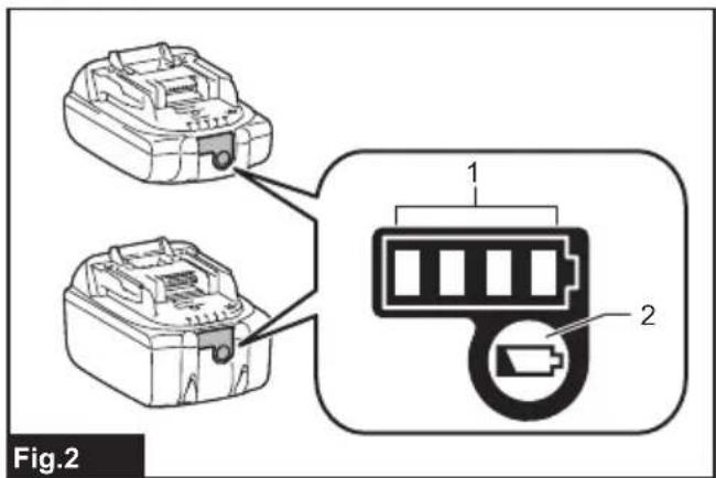
▶ Fig.2: 1. Indicator lamps 2. Check button
Press the check button on the battery cartridge to indicate the remaining battery capacity. The indicator lamps light up for a few seconds.
| Indicator lamps Remaining | capacity | ||
| Lighted Off | Blinking | ||
| 75% to 100% | |||
| 50% to 75% | |||
| 25% to 50% | |||
| 0% to 25% | |||
| Charge the battery. | |||
| The battery may have malfunctioned. | |||
NOTE: Depending on the conditions of use and the ambient temperature, the indication may differ slightly from the actual capacity.
NOTE: The first (far left) indicator lamp will blink when the battery protection system works.
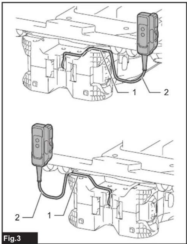
Switch box position
The switch box can be hooked on either side of the lower belt. Arrange the cord so that the switch box comes to your desired side. To prevent the cord from being damaged, pass the cord through the groove as illustrated.
▶ Fig.3: 1. Groove 2. Cord
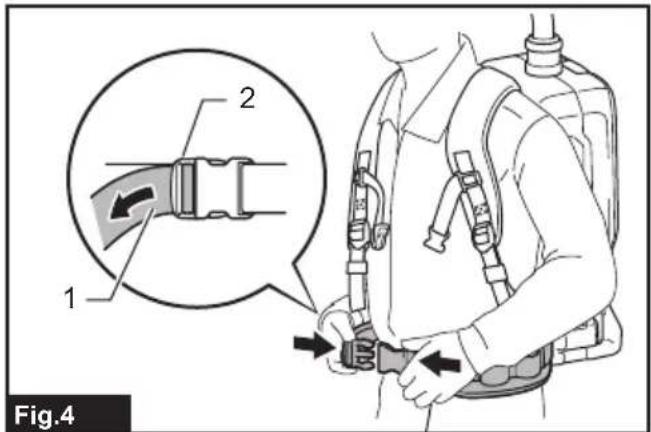
Adjusting belts
The tightness of the shoulder belts, upper and lower belts can be adjusted. Put your arms through the shoulder belts first then fasten the lower and upper belts. To tighten, pull the end of the strap as illustrated. To loosen, pull up the end of the fastener.
Lower belt
▶ Fig.4: 1. Strap 2. Fastener
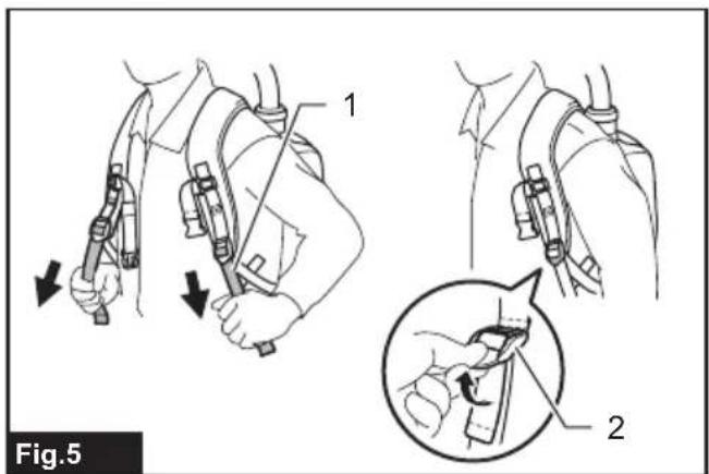
Shoulder belts
▶ Fig.5: 1. Strap 2. Fastener
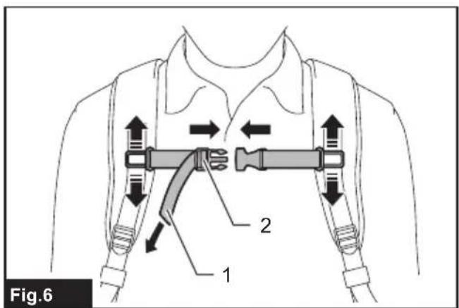
Upper belt
▶ Fig.6: 1. Strap 2. Fastener
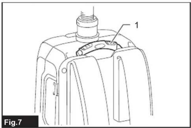
Carrying hook
CAUTION: Use the hanging/mounting parts for their intended purposes only. Using for unintended purpose may cause accident or personal injury.
Always grab the carrying hook when handling the vacuum cleaner body.
▶ Fig.7: 1. Carrying hook
Stand-by switch
The stand-by switch is the switch to turn on/off the wireless activation function. The vacuum cleaner is in the stand-by state regardless of the switch position and it runs when button is pushed.
▶ Fig.8: 1. Stand-by switch
| Switch position Status | ||
| AUTO I | (ON) | The vacuum cleaner is in the stand-by state and the wireless activation function is available. |
| O(OFF) | The vacuum cleaner is in the stand-by state however the wireless activation function is not available. | |
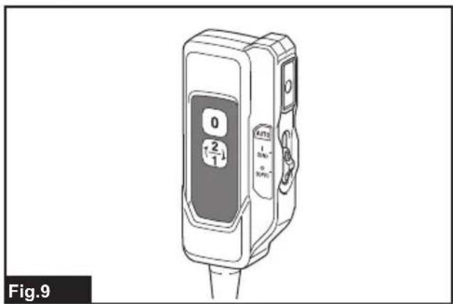
Switch action
To start vacuuming, press button once. The vacuum cleaner will start in the same suction power when you turned it off previously. When you press button while the vacuum cleaner is running, the suction power switches between normal (1) and higher (2) suction power. To turn off the vacuum cleaner, press button.
▶ Fig.9
NOTE: If you want to run the vacuum cleaner along with the switch operation of the tool connected to the vacuum cleaner (wireless activation function), set the stand-by switch to "I (ON)".
NOTE: To use the wireless activation function, finish the tool registration beforehand. Refer to "WIRELESS ACTIVATION FUNCTION" section for detail.
NOTE: When using the wireless activation function, you will not be able to stop the vacuuming by ☐ button.
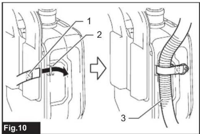
Hose band
Hose band can be used for holding the hose or free nozzle.
To secure the hose to the vacuum cleaner body, pass the hose band through the slot on the body. You can attach the hose band on either side.
▶ Fig.10: 1. Hose band 2. Slot 3. Hose
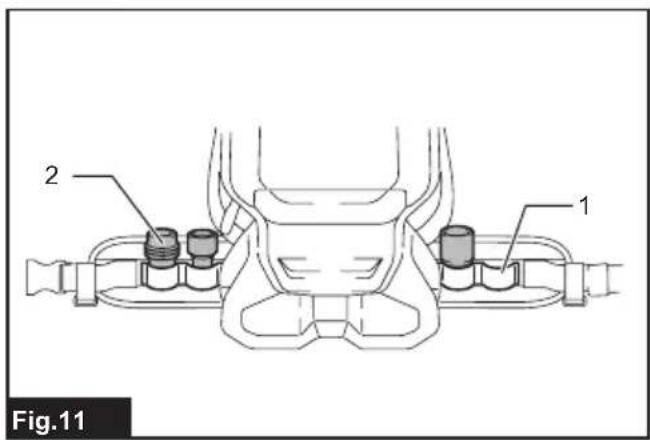
The loop on the lower belt can be used for carrying nozzles as illustrated.
▶ Fig.11: 1. Loop 2. Nozzles
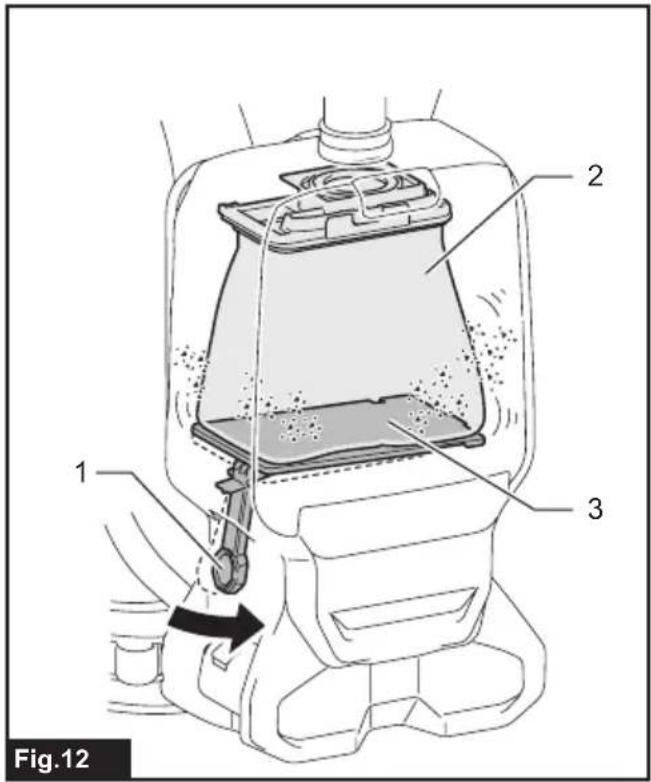
Dust beating system
Dust goes down when you pull the lever or walk with wearing the cleaner. This system helps the cleaner maintaining the suction power.
▶ Fig.12: 1. Lever 2. Filter bag/dust bag 3. Board
NOTE: This function works when the cleaner is switched off and the filter bag/dust bag contains a certain amount of dust to touch the board.
ASSEMBLY
⚠️CAUTION: Always be sure that the appliance is switched off and the battery cartridge is removed before carrying out any work on the appliance.
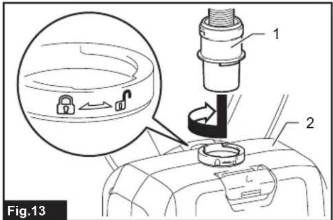
Assembling hose
Insert the hose cuff into the vacuum cleaner body and turn it clockwise.
▶ Fig.13: 1. Hose cuff 2. Vacuum cleaner body
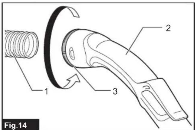
Connecting the tool
If the bent pipe assembly is attached to the hose, loosen the sleeve of bent pipe assembly and remove it.
▶ Fig.14: 1. Hose 2. Bent pipe assembly 3. Sleeve
-
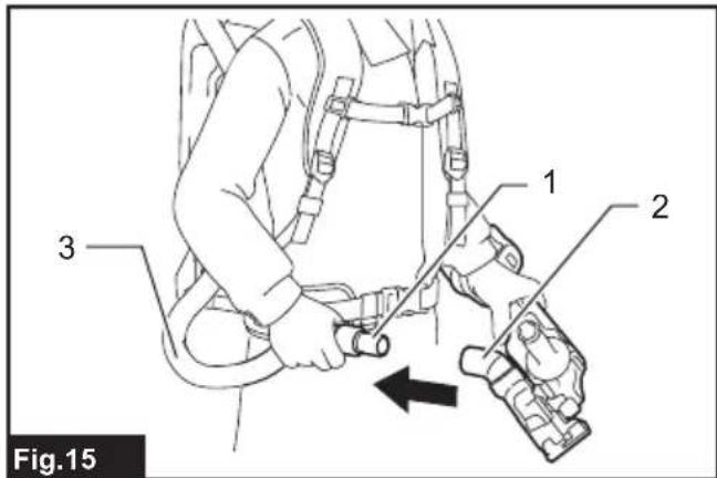
Attach the front cuff to the hose for dust extraction. When connecting the front cuff, make sure that it is securely screwed on the hose.
-
Connect the front cuff to the tool's extraction outlet.
▶ Fig.15: 1. Front cuff 2. Extraction outlet 3. Hose
The front cuff can be detached by turning it counterclockwise while holding the hose.
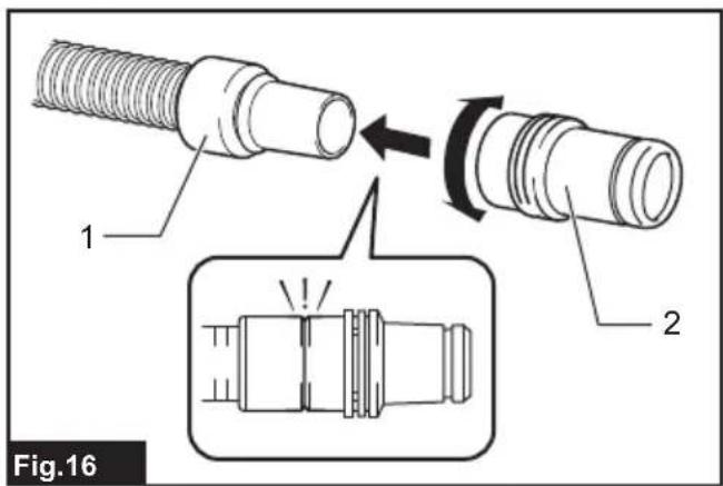
NOTE: Always use a suitable front cuff. When using the front cuff 24, attach it to the front cuff 22 that is connected to the hose.
▶ Fig.16: 1. Front cuff 22 2. Front cuff 24
Using as a cleaner
If you want to use this product as a cleaner, follow the below procedures.
NOTICE: If the front cuff is attached to the hose, remove it beforehand.
NOTE: The bent pipe assembly, extension wand, and nozzles are supplied as optional accessories in some countries.
NOTE: There are two types of bent pipe assembly; the one for slide-type extension wand and the one for ring-type extension wand. If you prepare the bent pipe assembly, choose the one for your desired extension wand type.
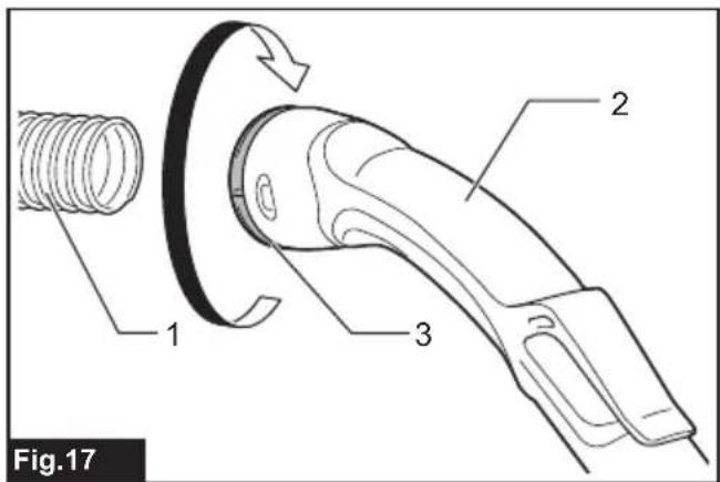
- Fasten the sleeve of bent pipe assembly onto the hose.
▶ Fig.17: 1. Hose 2. Bent pipe assembly 3. Sleeve
To remove the bent pipe assembly, loosen the sleeve of bent pipe assembly from the hose.
- Twist and insert the nozzle to the extension wand.
▶ Fig.18: 1. Extension wand 2. Free nozzle 3. T-shape nozzle 4. T-shape nozzle (slim)
NOTE: By twisting the nozzle while inserting, the nozzle can be attached to the extension wand securely.
- Follow the procedures below, depending on the type of the extension wand :
NOTE: The slide-type extension wand and the ring-type extension wand are not compatible with each other. If you want to change the slide-type extension wand to the ring-type extension wand or vice versa, change the bent pipe assembly also.
NOTE: The free nozzle can be attached to the bent pipe assembly directly.
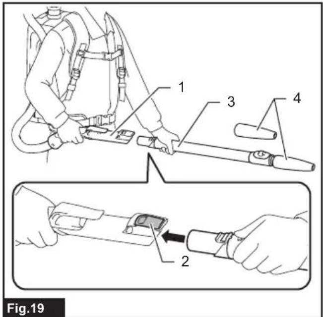
For the slide-type extension wand
Shoulder the vacuum cleaner body then insert the extension wand into the bent pipe assembly until it clicks. To disconnect, extract the extension wand with pressing the button.
▶ Fig.19: 1. Bent pipe assembly 2. Button 3. Slide-type extension wand 4. Free nozzle
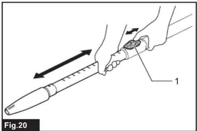
The length of the wand can be adjusted.
With pressing the slide button, adjust the wand length. The length is locked when releasing the slide button.
▶ Fig.20: 1. Slide button
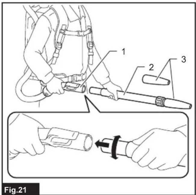
For the ring-type extension wand
Shoulder the vacuum cleaner body then twist and insert the extension wand into the bent pipe assembly. To disconnect, twist and extract it.
▶ Fig.21: 1. Bent pipe assembly 2. Ring-type extension wand 3. Free nozzle
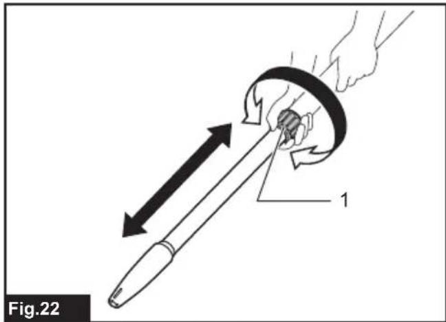
The length of the wand can be adjusted.
Loosen the ring on the wand and adjust the wand length. Tighten the ring at your desired length.
▶ Fig.22: 1. Ring
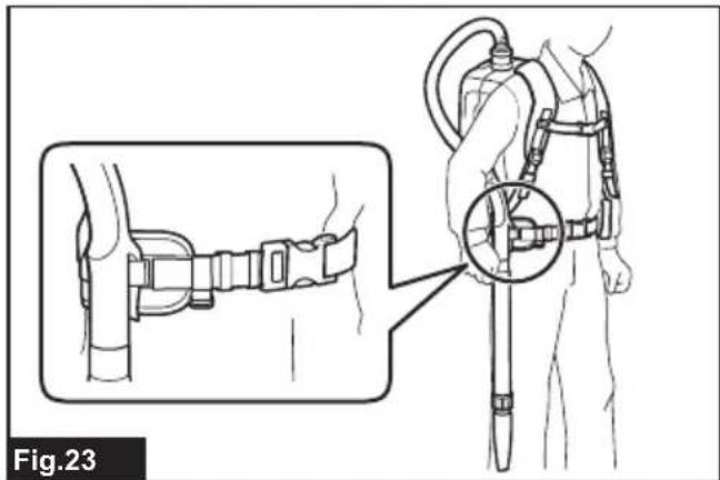
Hose hook
When you suspend the operation, the hook on the bent pipe assembly can be used for hanging the wand on the lower belt.
▶ Fig.23
Installing filter bag / dust bag
Optional accessory
CAUTION: Do not use a damaged filter bag. Always use the vacuum cleaner with the filter bag properly installed. Otherwise the vacuumed dust or particles may be exhausted from the cleaner and they may cause respiratory disease to the operator.
Install either dust bag or filter bag before using cleaner.
— Dust bag are usable many times repeatedly by cleaning it out.
— Filter bag is a throw-away type. Throw away the entire filter bag without emptying when it has become full.
NOTICE: When the filter bag is already full, replace with new one. When the dust bag is already full, empty it. Continuous use with the filter bag/dust bag full results in reduced suction power.
NOTICE: To prevent dust from getting into the motor:
— Make sure that the filter bag/dust bag is installed before use.
— Do not use a broken or ripped bag.
Otherwise the motor may be broken.
NOTICE: Do not fold the cardboard at its opening when installing the filter bag/dust bag.
NOTICE: The filter bag/dust bag for the cleaner is an important component for maintaining the appliance performance. Using non-genuine filter bag/dust bag may cause smoke or ignition.
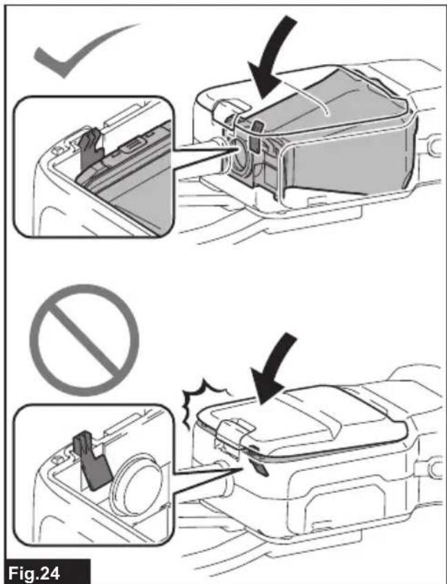
NOTE: When the filter bag/dust bag is not installed in the cleaner, the front cover does not close completely.
▶ Fig.24
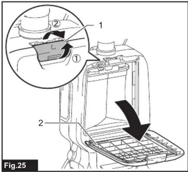
- Unlock the latch by lifting the bottom side. Push the grooved area to lift the front latching side. Pull the latch to open the lid.
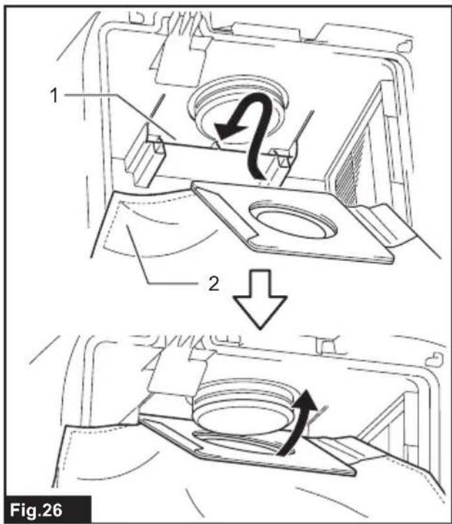
▶ Fig.25: 1. Hook 2. Lid - Insert the filter bag into the slit on the upper side of the room as illustrated.
▶ Fig.26: 1. Slit 2. Filter bag
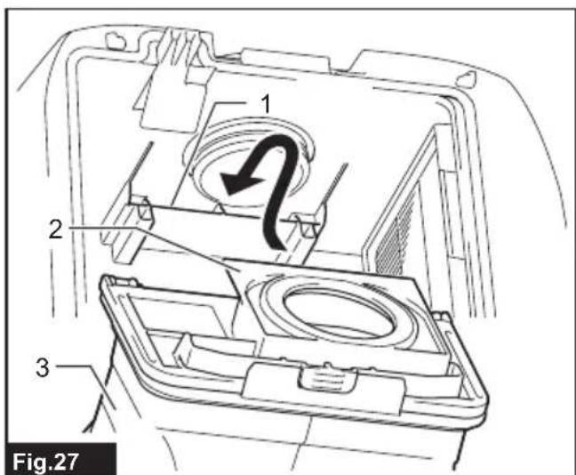
When using the dust bag, insert the brim of the dust bag into the slit.
▶ Fig.27: 1. Slit 2. Brim 3. Dust bag
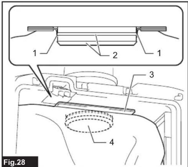
- Align the hole of the filter bag with the hose cuff and push the cardboard portion to the end. Make sure that the rubber ring on the filter bag goes over the rim on the hose cuff.
▶ Fig.28: 1. Rubber ring on the filter bag 2. Rim on the hose cuff 3. Cardboard portion of the filter bag 4. Hose cuff
OPERATION
WARNING: Operators shall be adequately instructed on the use of the vacuum cleaner.
WARNING: This vacuum cleaner is not suitable for picking up hazardous dust.
⚠️CAUTION: This cleaner is for dry use only.
⚠️CAUTION: This cleaner is for indoor use only.
⚠️CAUTION: Always insert the battery cartridge all the way until it locks in place. If you can see the red indicator on the upper side of the button, it is not locked completely. Insert it fully until the red indicator cannot be seen. If not, it may accidentally fall out of the appliance, causing injury to you or someone around you.
⚠️CAUTION: During operation, be conscious of the vacuum cleaner on your back. You may lose your balance if the vacuum cleaner body bumps against a wall or the hose is hooked by an obstacles.
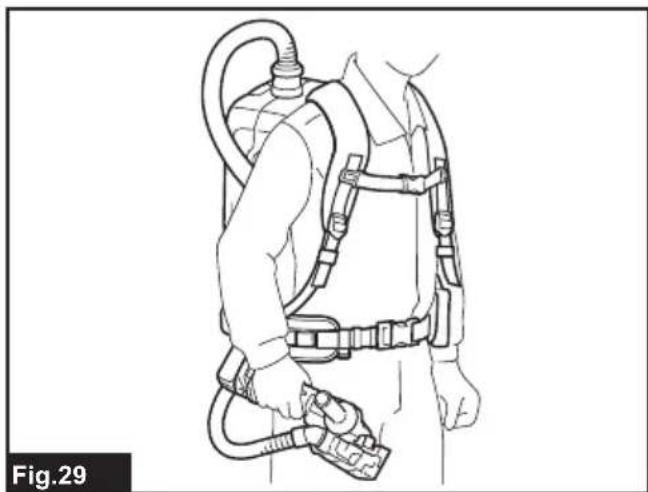
- Shoulder the vacuum cleaner body and fasten lower and upper belts. Adjust the tightness as necessary.
▶ Fig.29
- Press button to start vacuuming. To change the suction power, press button while the vacuum cleaner is running. The suction power switches between normal (1) and higher (2) suction power. Press button to stop.
▶ Fig.30
During the operation, hook the switch box on the lower belt or the ring.
▶ Fig.31: 1. Ring 2. Lower belt
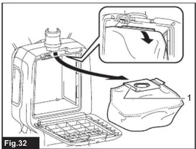
3. Replace the filter bag when it becomes full. Open the lid and take out the filter bag. Pull the strip on the side of the opening to shut the filter bag and dispose of the filter bag in whole.
▶ Fig.32: 1. Strip
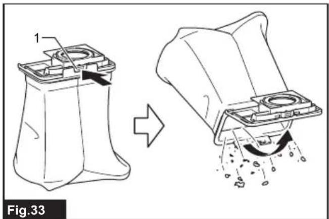
When using a dust bag, take out the dust bag and dispose of the dust by releasing the latch.
▶ Fig.33: 1. Latch
NOTICE: Do not put filter bag/dust bag or other heavy objects on the lid. The appliance may fall down.
NOTICE: Periodically check the filter bag if it is full. Continuous use with the filter bag full results in reduced suction power.
NOTICE: Do not use an used filter bag. The filter bag is designed for single use. Using filter bag repeatedly may cause clogging of the filter and results in damage to the cleaner. If you want to use the bag repeatedly, use a dust bag.
WIRELESS ACTIVATION FUNCTION
What you can do with the wireless activation function
The wireless activation function enables clean and comfortable operation. By connecting a supported tool to the cleaner, you can run the cleaner automatically along with the switch operation of the tool.
▶ Fig.34
NOTICE: Be sure to refer to the instruction manual of the tool when using the cleaner with wireless activation function.
NOTICE: Do not disassemble or tamper with the wireless unit.
NOTICE: To prevent dust coming into the slot of the wireless unit, always close the lid securely during operation and storage.
NOTICE: Do not remove the wireless unit while the power is being supplied. Doing so may cause a malfunction of the wireless unit.
NOTICE: Do not press the wireless activation button too hard and/or press the button with an object with a sharp edge.
NOTE: Wireless activation needs Makita tools equipped with the wireless unit.
NOTE: Prior to the initial use of the wireless activation function with each tool, the tool registration is required. Once the registration is finished with the tool, the re-registration is not required unless it is cancelled.
NOTE: Before registration, be sure that the wireless unit is properly inserted.
NOTE: One wireless unit can register up to 10 links with other wireless units. If more than 10 other wireless units are registered to one wireless unit, the one registered earliest will be cancelled automatically.
NOTE: The position of the wireless activation button varies depending on the tool.
NOTE: The cleaner also starts by pressing 21 button when the stand-by switch is set to "I (ON)".
However the button will not work when the wireless activation function is used.
Installing the wireless unit
⚠️CAUTION: Place the cleaner on a flat and stable surface when installing the wireless unit.
NOTICE: Clean the dust and dirt on the cleaner before installing the wireless unit. Dust or dirt may cause malfunction if it comes into the slot of the wireless unit.
NOTICE: To prevent the malfunction caused by static, touch a static discharging material, such as a metallic part, before picking up the wireless unit.
NOTICE: When installing the wireless unit, always be sure that the wireless unit is inserted in the correct direction and the lid is completely closed.
- Open the lid on the cleaner as shown in the figure.
▶ Fig.35: 1. Lid
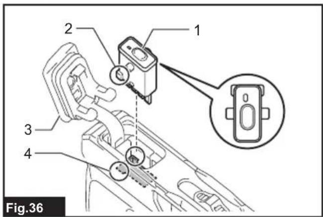
- Insert the wireless unit to the slot and then close the lid.
When inserting the wireless unit, align the projections with the recessed portions on the slot.
▶ Fig.36: 1. Wireless unit 2. Projection 3. Lid 4. Recessed portion
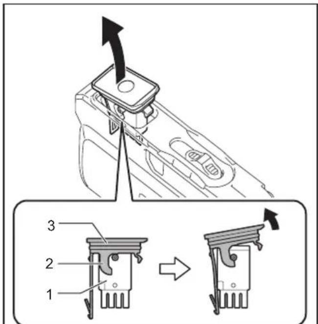
When removing the wireless unit, open the lid slowly.
The hooks on the back of the lid will lift the wireless unit as you pull up the lid.
▶ Fig.37: 1. Wireless unit 2. Hook 3. Lid
After removing the wireless unit, keep it in the supplied case or a static-free container.
NOTICE: Always use the hooks on the back of the lid when removing the wireless unit. If the hooks do not catch the wireless unit, close the lid completely and open it slowly again.
Tool registration for the cleaner
NOTE: A Makita tool supporting the wireless activation function is required for the tool registration.
NOTE: Finish installing the wireless unit to the tool before starting the tool registration.
NOTE: During the tool registration, do not pull the switch trigger on the tool or push the cleaner's switch for vacuuming.
NOTE: Refer to the instruction manual of the tool, too.
If you wish to activate the cleaner along with the switch operation of the tool, finish the tool registration beforehand.
- Install the wireless units to the cleaner and the tool, respectively.
- Install the batteries to the cleaner and the tool.
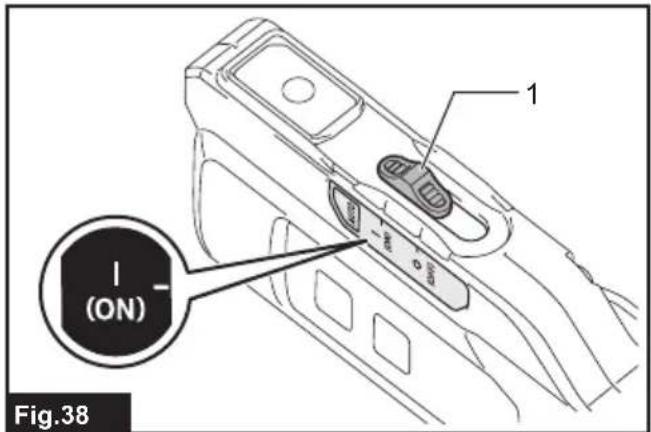
- Set the stand-by switch on the cleaner to "I (ON)".
▶ Fig.38: 1. Stand-by switch
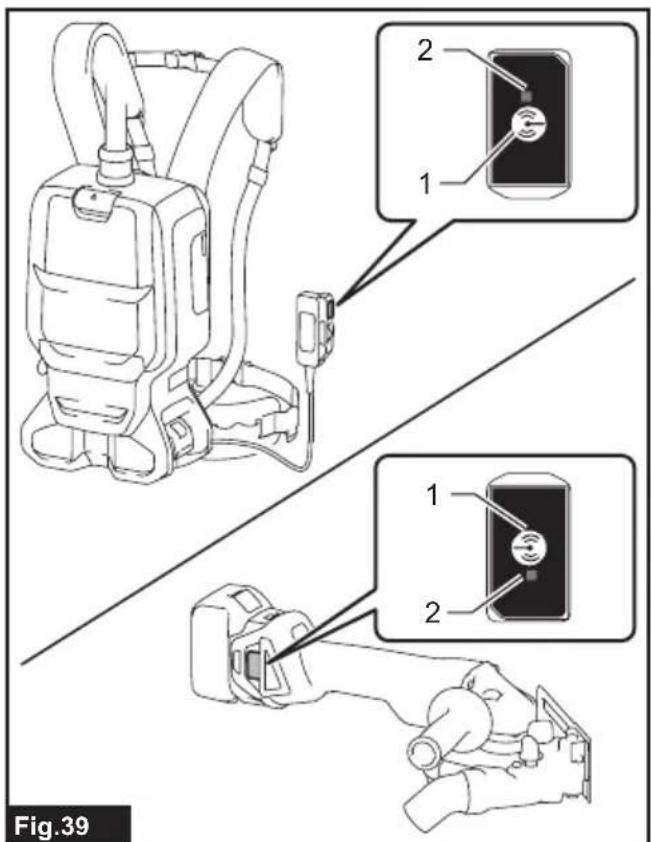
- Press the wireless activation button on the cleaner for 3 seconds until the wireless activation lamp blinks in green. And then press the wireless activation button on the tool in the same way.
▶ Fig.39: 1. Wireless activation button 2. Wireless activation lamp
If the cleaner and the tool are linked successfully, the wireless activation lamps will light up in green for 2 seconds and start blinking in blue.
NOTE: The wireless activation lamps finish blinking in green after 20 seconds elapsed. Press the wireless activation button on the tool while the wireless activation lamp on the cleaner is blinking. If the wireless activation lamp does not blink in green, push the wireless activation button briefly and hold it down again.
NOTE: When performing two or more tool registration for the cleaner, finish the tool registration one by one.
Starting the wireless activation function
NOTE: Finish the tool registration for the cleaner for wireless activation.
NOTE: Always place the cleaner so that you can see the status of the wireless activation lamp.
NOTE: Refer to the instruction manual of the tool, too.
After registering a tool to the cleaner, the cleaner will automatically runs along with the switch operation of the tool.
- Install the wireless units to the cleaner and the tool, respectively.
- Install the batteries to the cleaner and the tool.
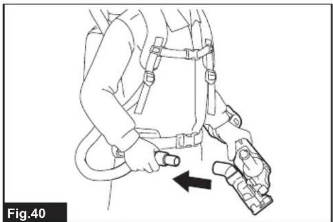
- Connect the hose of the cleaner with the tool.
▶ Fig.40
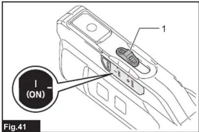
- Set the stand-by switch on the cleaner to "I (ON)". The wireless activation lamp will blink in blue.
▶ Fig.41: 1. Stand-by switch
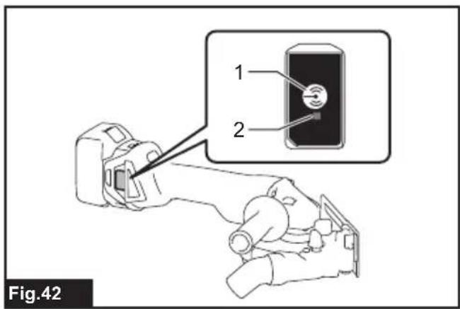
- Push the wireless activation button on the tool briefly. The wireless activation lamp will blink in blue.
▶ Fig.42: 1. Wireless activation button 2. Wireless activation lamp
- Pull the switch trigger of the tool. Check if the cleaner runs while the switch trigger on the tool is being pulled.
⚠️CAUTION: Always check if the wireless activation function works before starting a work with the tool.
To stop the wireless activation, push the wireless activation button on the tool or set the stand-by switch on the cleaner to "O (OFF)".
NOTE: The wireless activation lamp on the tool will stop blinking in blue when there is no operation for 2 hours. In this case, press the wireless activation buttons on the tool again.
NOTE: The cleaner starts/stops with a delay. There is a time lag when the cleaner detects a switch operation of the tool.
NOTE: The transmission distance of the wireless unit may vary depending on the location and surrounding circumstances.
NOTE: When two or more tools are registered to one cleaner, the cleaner may start running even if you don't pull the switch trigger because other user is using the wireless activation function.
Cancelling tool registration for the cleaner
Perform the following procedure when cancelling the tool registration for the cleaner.
- Install the wireless units to the cleaner and the tool, respectively.
- Install the batteries to the cleaner and the tool.
- Set the stand-by switch on the cleaner to "I (ON)".
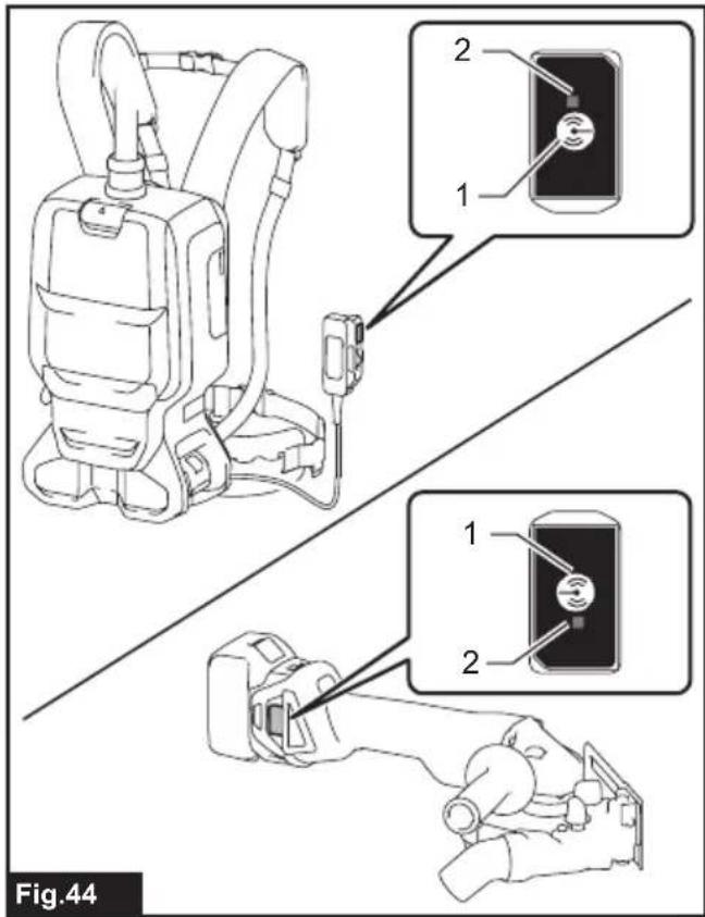
▶ Fig.43: 1. Stand-by switch - Press the wireless activation button on the cleaner for 6 seconds. The wireless activation lamp blinks in green and then become red. After that, press the wireless activation button on the tool in the same way.
▶ Fig.44: 1. Wireless activation button 2. Wireless activation lamp
If the cancellation is performed successfully, the wireless activation lamps will light up in red for 2 seconds and start blinking in blue.
NOTE: The wireless activation lamps finish blinking in red after 20 seconds elapsed. Press the wireless activation button on the tool while the wireless activation lamp on the cleaner is blinking. If the wireless activation lamp does not blink in red, push the wireless activation button briefly and hold it down again.
Erasing all tool registrations
You can erase all tool registrations from the cleaner as follows.
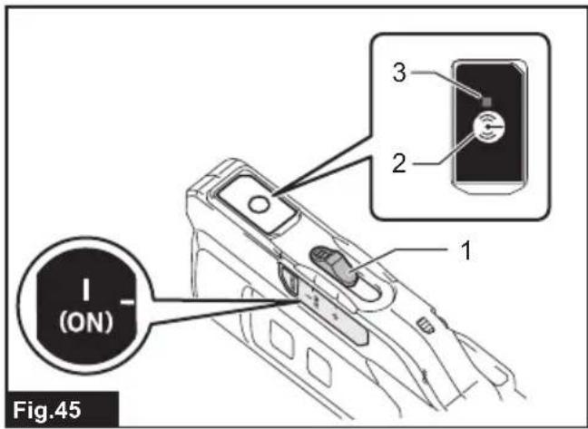
▶ Fig.45: 1. Stand-by switch 2. Wireless activation button 3. Wireless activation lamp
- Install the wireless unit to the cleaner.
- Install the batteries to the cleaner.
- Set the stand-by switch to "I (ON)".
-
Hold down the wireless activation button for about 6 seconds until the wireless activation lamp blinks in red (about twice per one second).
-
When the wireless activation lamp starts blinking in red, release your finger from the wireless activation button. Thereafter, hold down the wireless activation button again for about 6 seconds.
-
When the wireless activation lamp starts blinking fast (about 5 times per one second) in red, release your finger from the wireless activation button. When the wireless activation lamp lights up in red and later lights off, all tool registrations are erased.
NOTE: If the wireless activation lamp does not blink in red, press the wireless activation button briefly and try again.
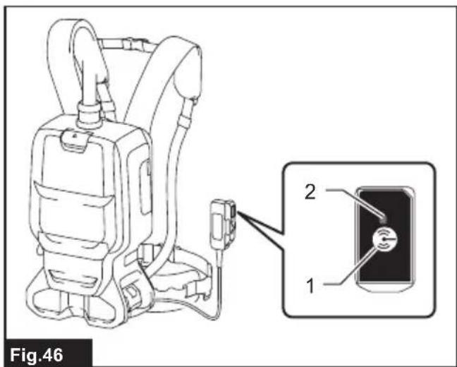
Description of the wireless activation lamp status
▶ Fig.46: 1. Wireless activation button 2. Wireless activation lamp
The wireless activation lamp shows the status of the wireless activation function. Refer to the below table for the meaning of the lamp status.
| Status Wireless activation lamp Description | |||||
| Color | On | Blinking | Duration (approximate) | ||
| Standby B | ue | Cleaner: continuingTool: 2 hours | Waiting for the tool registration or the wireless activation function is available.The lamp on the cleaner blinks when the stand-by switch is set in "I (ON)". The lamp on the tool blinks when the wireless activation button is pushed. The lamp on the tool will automatically turn off when no operation is performed for 2 hours. | ||
| When the tool is running. | The wireless activation of the cleaner is available and the tool is running. | ||||
| Tool registration | Green | 20 seconds Ready for the tool registration. Searching the tool to be registered. | |||
| 2 seconds The tool registration has been finished. The wireless activation lamp will start blinking in blue. | |||||
| Cancelling/ erasing tool registration | Red | (slow: 2 times/sec.) | 20 seconds Ready for the cancellation of the tool registration. Searching the tool to be cancelled. | ||
| (fast: 5 times/sec.) | When the wireless acti- vation button is pressed down. | Ready to erase all tool registrations. | |||
| 2 seconds The tool registration has been cancelled/erased. The wireless activation lamp will start blinking in blue. | |||||
| Others Red | 3 seconds The power is supplied to the wireless unit and the wireless activa- tion function is starting up. | ||||
| Off | - | - | The stand-by switch is not set to "I (ON)". | ||
Troubleshooting for wireless activation function
Before asking for repairs, conduct your own inspection first. If you find a problem that is not explained in the manual, do not attempt to dismantle the tool. Instead, ask Makita Authorized Service Centers, always using Makita replacement parts for repairs.
| State of abnormality Probable cause | (malfunction) Remedy | |
| The wireless activation lamp does not light/blink. | The wireless unit is not installed into the cleaner and/or the tool.The wireless unit is improperly installed into the cleaner and/or the tool. | Install the wireless unit correctly. |
| The terminal of the wireless unit and/or the slot is dirty. | Gently wipe off dust and dirt on the terminal of the wireless unit and clean the slot of the cleaner and/or the tool. | |
| The wireless activation button on the tool have not been pushed. | Push the wireless activation button on the tool briefly. Make sure that the wireless activation lamp is blinking in blue. | |
| The stand-by switch on the cleaner is not set to " I (ON)". | Set the stand-by switch on the cleaner to " I (ON)". | |
| No power supply Supply the power to the | tool and the cleaner. | |
| Cannot finish tool registration / cancelling tool registration successfully. | The wireless unit is not installed into the cleaner and/or the tool.The wireless unit is improperly installed into the cleaner and/or the tool. | Install the wireless unit correctly. |
| The terminal of the wireless unit and/or the slot is dirty. | Gently wipe off dust and dirt on the terminal of the wireless unit and clean the slot of the cleaner and/or the tool. | |
| The stand-by switch on the cleaner is not set to " I (ON)". | Set the stand-by switch on the cleaner to " I (ON)". | |
| No power supply Supply the power to the | tool and the cleaner. | |
| Incorrect operation Push the wireless act | ivation button briefly and perform the tool registration/cancellation procedures again. | |
| The tool and cleaner are away from each other (out of the transmission range). | Get the tool and the cleaner closer to each other. The maximum transmission distance is approximately 10 m however it may vary according to the circumstances. | |
| Before finishing the tool registration/cancellation;- the switch trigger on the tool is pulled or;- the cleaner's switch to start vacuuming is pushed. | Push the wireless activation button briefly and perform the tool registration/cancellation procedures again. | |
| The tool registration procedures for the tool or the cleaner has not been finished. | Perform the tool registration procedures for the tool and the cleaner at the same timing. | |
| Radio disturbance by other appliances which generate high-intensity radio waves. | Keep the tool and the cleaner away from the appliances such as Wi-Fi devices and microwave ovens. | |
| The cleaner does not run along with the switch operation of the tool. | The wireless unit is not installed into the cleaner and/or the tool.The wireless unit is improperly installed into the cleaner and/or the tool. | Install the wireless unit correctly. |
| The terminal of the wireless unit and/or the slot is dirty. | Gently wipe off dust and dirt on the terminal of the wireless unit and clean the slot of the cleaner and/or the tool. | |
| The wireless activation button on the tool have not been pushed. | Push the wireless activation button on the tool briefly. Make sure that the wireless activation lamp is blinking in blue. | |
| The stand-by switch on the cleaner is not set to " I (ON)". | Set the stand-by switch on the cleaner to " I (ON)". | |
| More than 10 tools are registered to the cleaner. | Perform the tool registration again.If more than 10 tools are registered to the cleaner, the tool registered earliest will be cancelled automatically. | |
| The cleaner erased all tool registrations. | Perform the tool registration again. | |
| No power supply Supply the power to the | tool and the cleaner. | |
| The tool and cleaner are away from each other (out of the transmission range). | Get the tool and the cleaner closer to each other.The maximum transmission distance is approximately 10 m however it may vary according to the circumstances. | |
| Radio disturbance by other appliances which generate high-intensity radio waves. | Keep the tool and the cleaner away from the appliances such as Wi-Fi devices and microwave ovens. | |
| The cleaner runs while the tool's switch trigger is not pulled. | Other users are using the wireless activation of the cleaner with their tools. | Perform one of the following way;- set the stand-by switch on the cleaner to "O" position or;- turn off the wireless activation button of the other tools or;- cancel the tool registration of the other tools. |
| Cannot erase all tool registrations in the cleaner. | Pressing the wireless button on the tool. | Press the wireless button on the cleaner for erasing all tool registrations. |
| The stand-by switch on the cleaner is not set to " I (ON)". | Set the stand-by switch on the cleaner to " I (ON)". | |
| The wireless activation button is not held down correctly. | Hold down the wireless activation button for more than 6 seconds and then release it when the wireless activation lamp blinks in red. Hold down the wireless activation button for more than 6 seconds again until the wireless activation button rapidly blinks in red and then release the button. |
MAINTENANCE
⚠️CAUTION: Always be sure that the appliance is switched off and the battery cartridge is removed before attempting to perform inspection or maintenance.
NOTICE: Never use gasoline, benzine, thinner, alcohol or the like. Discoloration, deformation or cracks may result.
To maintain product SAFETY and RELIABILITY, repairs, any other maintenance or adjustment should be performed by Makita Authorized or Factory Service Centers, always using Makita replacement parts.
Cleaning the HEPA filter
CAUTION: Do not use the vacuum cleaner without a filter or continue to use dirty or damaged filter. Vacuumed dust or particles may be exhausted from the cleaner and they may cause respiratory disease to the operator.
NOTICE: To keep optimum suction power and clean exhaust, clean the filter periodically. If enough suction power is not obtained even after the cleaning, replace the filter with new one.
NOTICE: To prevent the filter from being damaged, do not use following tools and similar items for cleaning :
— Air duster
— High pressure washer
— Tools made of hard materials such as a metallic brush
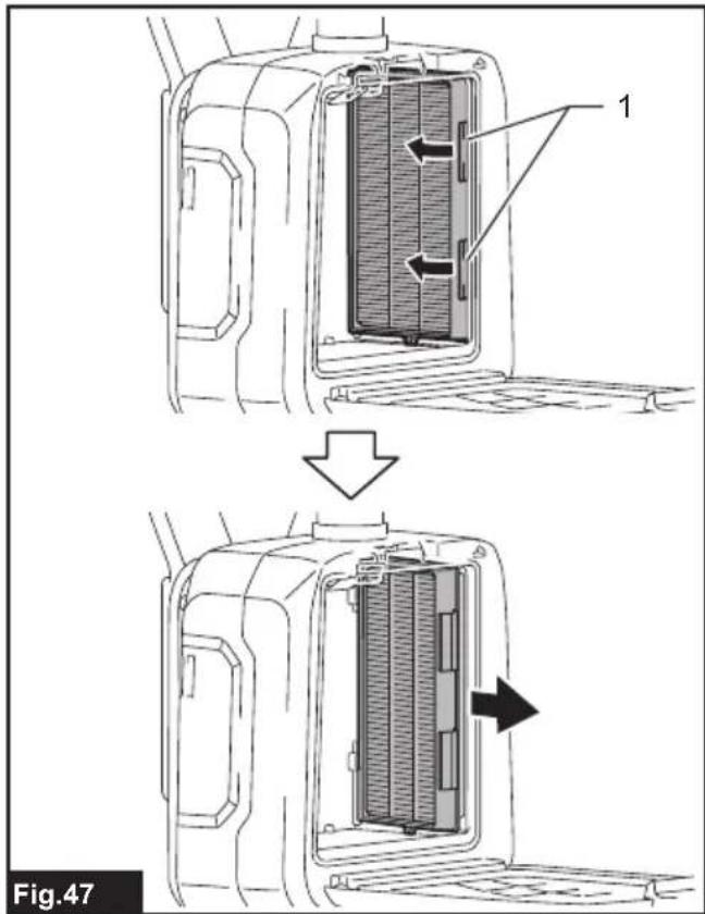
- Open the lid and take out the filter bag/dust bag. Release the hook on the filter and remove it from the vacuum cleaner body.
▶ Fig.47: 1. Hook
-
Beat the dust off from the filter. The filter can be washed with water. Rinse away the dust and particles on the filter every 1 or 2 month. After that, dry the filter completely in a shaded and well-ventilated place to prevent unpleasant odor or malfunctions.
-
To install the filter, insert the side without the hooks into the groove then push in the filter until the hooks are secured with a click.
▶ Fig.48: 1. Groove 2. HEPA filter 3. Hook
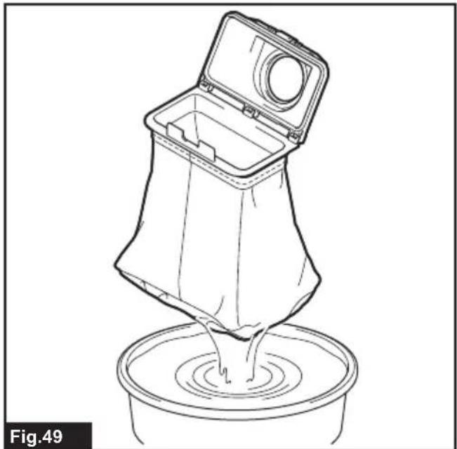
Cleaning the dust bag
Regularly clean the dust bag with soap and water. Turn the dust bag inside out and remove the sticky dust. Wash lightly by hand and rinse well with water. Dry completely before installing to the vacuum cleaner.
▶ Fig.49
NOTICE: Wet dust bag lowers the vacuuming performance as well as the life of the motor.
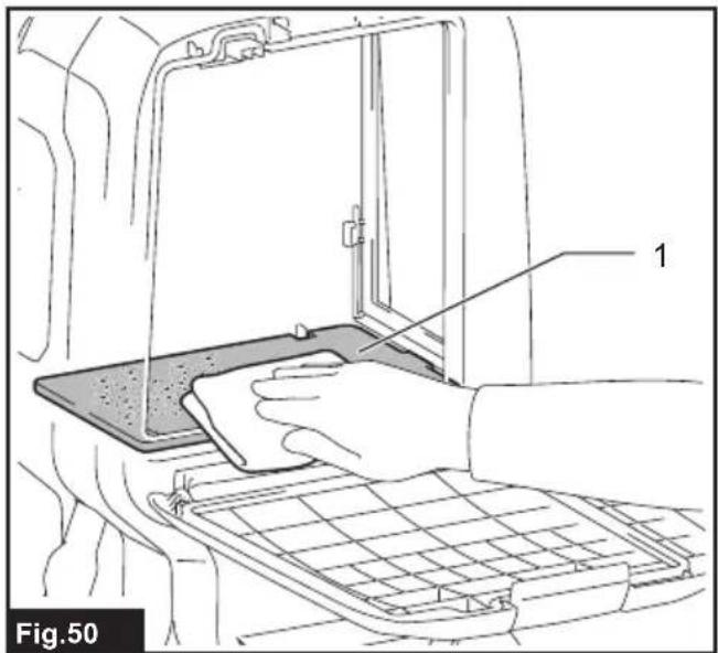
Cleaning the room for filter bag/dust bag
When cleaning the room for filter bag/dust bag, remove and wipe the board inside.
▶ Fig.50: 1. Board
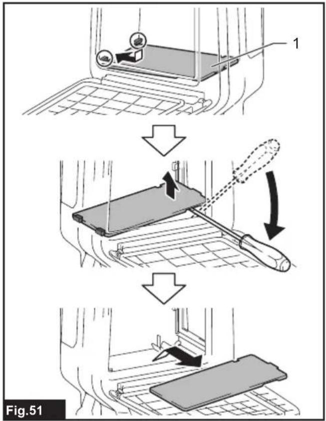
Removing the board
- Remove the HEPA filter. Refer to the section for cleaning the HEPA filter for how to remove.
- Push down the board, and slide it to left until the board touches the wall.
- Lift the right side of the board up and take it out.
▶ Fig.51: 1. Board
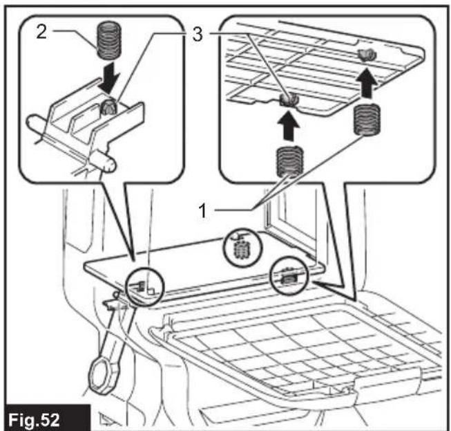
The board is supported by three springs.
If the springs came off from the board or the lever, reattach them as illustrated.
▶ Fig.52: 1. Spring for board 2. Spring for lever 3. Projection
NOTE: Attach the springs securely so that the springs touch the root of the projections.
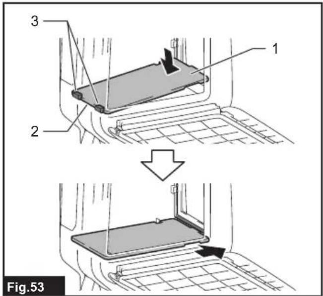
Attaching the board
- Insert the straight side of the board into the catches in the lower left side of the room.
- Put the right side of the board in place.
▶ Fig.53: 1. Board 2. Straight side 3. Catch
OPTIONAL ACCESSORIES
CAUTION: These accessories or attachments are recommended for use with your Makita product specified in this manual. The use of any other accessories or attachments might present a risk of injury to persons. Only use accessory or attachment for its stated purpose.
If you need any assistance for more details regarding these accessories, ask your local Makita Service Center.
- Hose (for dust extraction type)
- Hose (for vacuum cleaner type)
- Extension wand
- Free nozzle
- T-shape nozzle
- Seat nozzle
- Corner nozzle
- Shelf brush
- Round brush
- Filter bag
- Dust bag
- Front cuff
- HEPA filter
- Wireless unit
- Cyclone attachment
- Makita genuine battery and charger
NOTE: Some items in the list may be included in the tool package as standard accessories. They may differ from country to country.
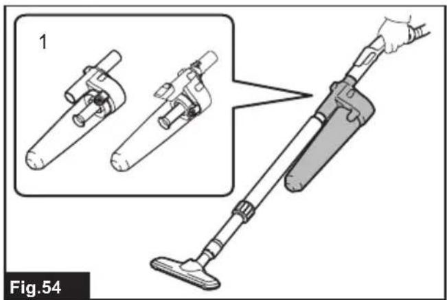
Cyclone attachment
NOTE: When using the cyclone attachment with this appliance, the bent pipe is also requied.
▶ Fig.54: 1. Cyclone attachment
About the cyclone attachment
Using the cleaner with the cyclone attachment installed reduces the amount of dust that enters the dust bag, which helps to prevent the suction force from weakening. In addition, cleaning after use is also simple.
CAUTION: Always be sure that the tool is switched off and the battery cartridge is removed before carrying out any work on the tool. If the battery cartridge is left inserted, the cleaner may start unexpectedly and result in injury.
CAUTION: Clean the mesh filter of the cyclone attachment and the dust bag of the cleaner unit when they become clogged.
Continued use in the clogged condition may result in heating or smoke.
NOTICE: When the cyclone attachment is attached, do not use the cyclone attachment in the horizontal or upward facing condition. Doing so may cause the mesh filter to become clogged.
NOTICE: Always use the cleaner with the dust bag installed, even when using the cyclone attachment. Using the cleaner without the dust bag installed may result in a motor malfunction.
NOTE: Check that the cyclone attachment, cleaner, and straight pipe are locked properly before use.
NOTE: Empty the dust case of the cyclone attachment and the dust bag of the cleaner when dust has accumulated. Continued use will result in weakened suction force.
NOTE: You can use the cyclone attachment with or without lock function.
NOTE: To install or remove the cyclone attachment, refer to the section "Using as a cleaner".
Disposing of dust
When dust has accumulated up to the full line of the dust case, follow the procedure below and dispose of the dust.
- Hold the dust case firmly, press and hold the two buttons, and remove the dust case.
▶ Fig.55: 1. Full line 2. Dust case 3. Button (two locations) 4. Mesh filter
-
Dispose of the dust inside the dust case and remove any dust and powder adhered to the surface of the mesh filter.
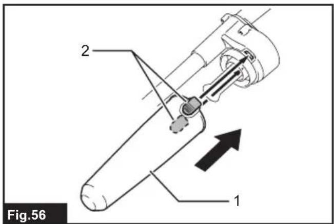
-
Insert the dust case all the way until the two buttons lock with a click.
▶ Fig.56: 1. Dust case 2. Button (two locations)
NOTE: Check that the cyclone attachment, cleaner, and straight pipe are locked properly before restarting operation.
NOTE: If the suction force does not recover even after disposing of the dust and cleaning the mesh filter, check whether dust has accumulated in the dust bag of the cleaner or clogging has occurred.
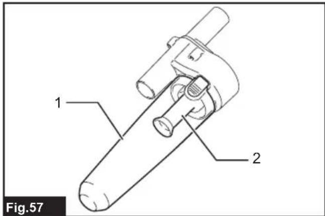
Cleaning
When the dust case becomes dirty or the mesh filter is clogged, remove and wash them with water. (Refer to "Disposing of dust" for the removal procedure.)
Dry the parts thoroughly before reinstallation and use.
▶ Fig.57: 1. Dust case 2. Mesh filter
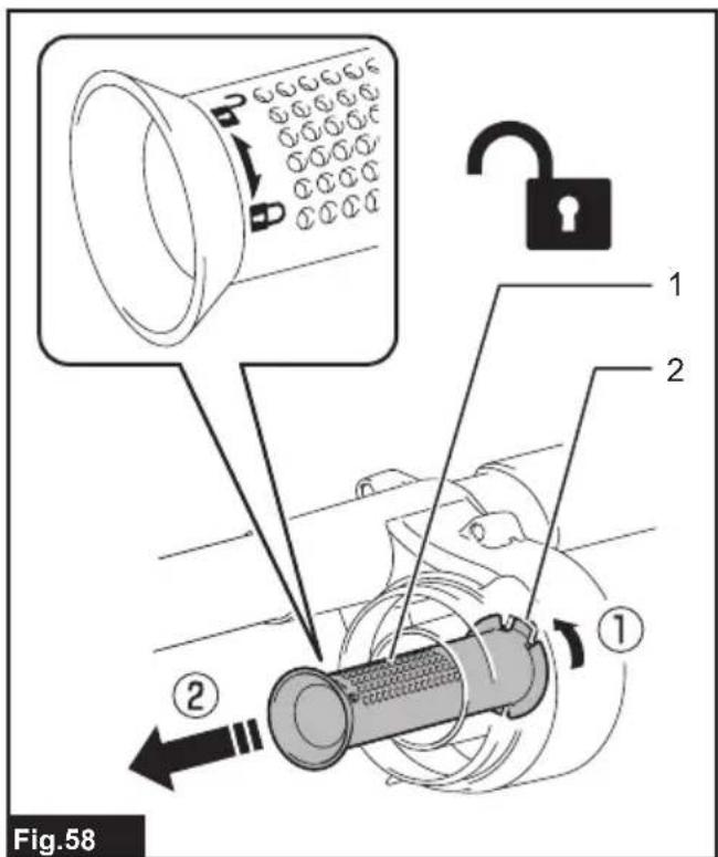
When the mesh filter gets dirty badly, clean it in the following procedures.
- Turn the mesh filter counterclockwise and remove it while the hooks are unlocked.
▶ Fig.58: 1. Mesh filter 2. Hook
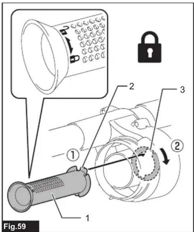
-
Remove the dust on the mesh filter and then wash it with water. After that, dry it thoroughly.
-
Insert the mesh filter into the base while the hooks are aligned with the port. Turn the mesh filter clockwise until the hooks are locked with a click. Make sure that the mesh filter is installed securely.
▶ Fig.59: 1. Mesh filter 2. Hook 3. Port
AVERTISSEMENT
▶ Fig.11: 1. Arceau 2. Raccords
▶ Fig.20: 1. Bouton coulissant
▶ Fig.25: 1. Crochet 2. Couvercle
▶ Fig.31: 1. Bague 2. Ceinture inférieure
▶ Fig.50: 1. Plateau
Retrait du plateau
▶ Fig.51: 1. Plateau
▶ Abb.25: 1. Haken 2. Klappe
⚠ WAARSCHUWING: Draag gehoorbescherming.
VEILIGHEIDSWAAR- SCHUWINGEN
▶ Fig.5: 1. Riem 2. Gesp
Bovenste riem
▶ Fig.6: 1. Riem 2. Gesp
Draaghandgreep
▶ Fig.7: 1. Draaghandgreep
Standbyschakelaar
▶ Fig.11: 1. Lus 2. Mondstuk
Stofklopsysteem
▶ Fig.20: 1. Schuifknop
▶ Fig.27: 1. Sleuf 2. Rand 3. Stofzak
OPTIONELE ACCESSOIRES
▶ Fig.59: 1. Gaasfilter 2. Haak 3. Opening
ADVERTENCIA
▶ Fig.3: 1. Ranura 2. Cable
Correas de ajuste
▶ Fig.11: 1. Ojal 2. Boquillas
▶ Fig.27: 1. Slids 2. Rand 3. Støvpose
▶ Eik.35: 1. Kappáki