POF 1200 D3 - Milling machine PARKSIDE - Free user manual and instructions
Find the device manual for free POF 1200 D3 PARKSIDE in PDF.

User questions about POF 1200 D3 PARKSIDE
0 question about this device. Answer the ones you know or ask your own.
Ask a new question about this device
Download the instructions for your Milling machine in PDF format for free! Find your manual POF 1200 D3 - PARKSIDE and take your electronic device back in hand. On this page are published all the documents necessary for the use of your device. POF 1200 D3 by PARKSIDE.
USER MANUAL POF 1200 D3 PARKSIDE
ROUTER / OBERFRÄSE / DÉFONCEUSE POF 1200 D3
GB
ROUTER
Translation of the original instructions
FR
DEFONCEUSE
Before reading, unfold the page containing the illustrations and familiarise yourself with all functions of the device.
DE
GB Translation of the original instructions Page 1
| DE | Originalbetriebsanleitung | Seite | 15 |
| FR | Traduction des instructions d'origine Page 29 | ||
| NL | Vertaling van de originele gebruiksaanwijzing | Pagina 45 | |
| CZ | Překlad originálniho provozního námovodu Strana 59 | ||
| PL | Tlhumaczenie oryginalej instrukčji obstugi | Strona 73 | |
| SK | Preklad originálneho námovodu na obsluhu | Strana 87 | |
| ES | Traducción del manual de instrucciones original | Pagina 99 | |
| DK | Oversætelse of den originale driftsvejledning | Side | 113 |
A
B
C
Contents
Introduction 2
Intended use 2
Features 2
Package contents 3
Technical specifications 3
General power tool safety warnings 3
1.Work area safety 4
2. Electrical safety 4
3. Personal safety 4
4. Power tool use and care 5
5. Service 5
Safety instructions for routers 5
Supplementary notes 5
Original accessories/auxiliary equipment 6
Before use 6
Milling cutter set 6
Inserting a milling tool 6
Connecting the dust extraction adapter 6
Reducer 6
Changing the collet chuck 7
Fitting the rip fence 7
Setting up 7
Switching on and off 7
Preselecting the rotation speed 7
Setting the milling depth 7
Re-adjusting the milling depth 8
Setting the milling depth with the step stop 8
Milling direction 8
Milling operation 9
Fitting the copy sleeve 9
Milling with the copy sleeve 9
Milling with the rip fence 9
Adjusting the rip fence (fig. H) 9
Milling with a compass 9
Maintenance and cleaning 10
Disposal 10
Kompernass Handels GmbH warranty 11
Service 12
Importer
Translation of the original Conformity Declaration 13
ROUTER POF 1200 D3
Introduction
Congratulations on the purchase of your new appliance. You have chosen a high-quality product. The operating instructions are part of this product. They contain important information about safety, usage and disposal. Before using the product, please familiarise yourself with all operating and safety instructions. Use the product only as described and for the range of applications specified. Please also pass these operating instructions on to any future owner.
Intended use
This appliance is designed for milling grooves, edges, profiles and oblong holes in wood, plastic and lightweight materials on a fixed support, as well as for copy milling. The appliance is not intended for use outside. Any other uses of or modifications to the appliance are deemed to be improper usage and may result in serious physical injury. Not for commercial use.
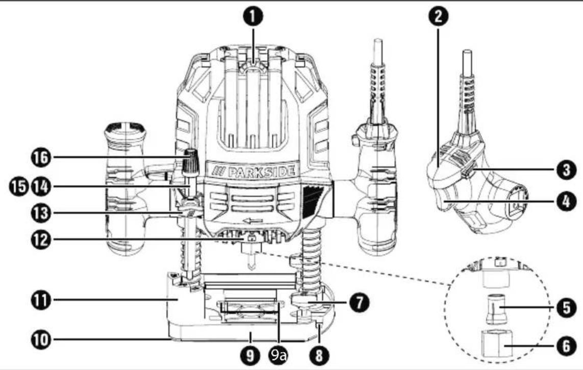
Features
Fig. A
Speed preselection
2 Handle
3 Safety lock-out
ON/OFF switch
5 Collet chuck 8 mm
6 Union nut
Locking screw
8 Guide rail
9 Base plate
9a Holes for the dust extraction adapter
10 Skid plate
Step stop
12 Spindle locking button
13 Locking screw
1 Depth stop
15 Milling depth adjustment scale
16 Dial (fine milling depth adjustment)
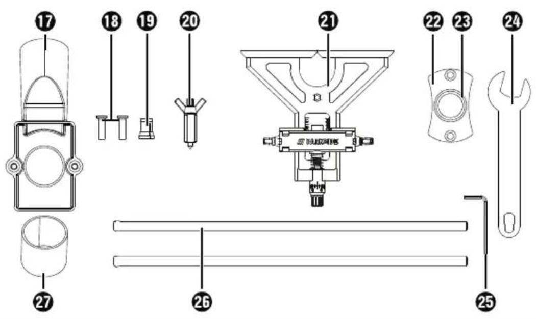
Fig.B
Dust extraction adapter
Screw
19 Collet chuck 6 mm
20 Centring point
Rip fence
Copy sleeve
Race
20 Open-ended spanner with slotted hole
Hex key
26 Sliding rod
7 Reducer
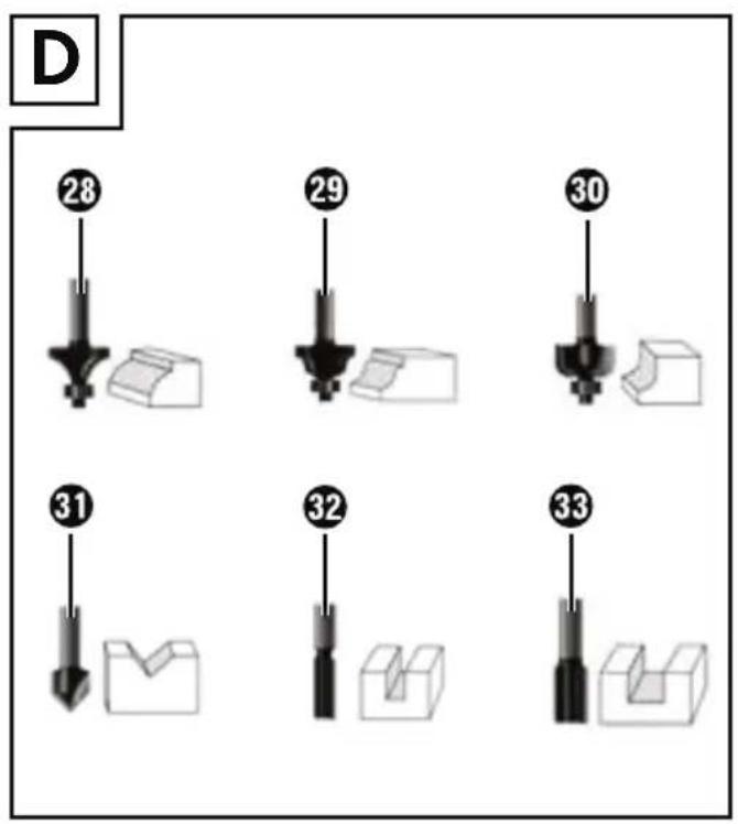
Fig. D
28 Rounding cutter 22mm / R6.3mm
29 Profile cutter 25mm / R4mm
30 Chamfer milling cutter 22mm / R6.3mm
V-slot milling cutter 12,7mm/angle 90^
32 Slotting cutter 6mm
Slotting cutter 12 mm
Fig. F
Clamping lever
Fig. H
35 Dial
Scale ring
37 Wing screws for adjusting the sliding rod
Scale
39 Screws for the sliding jaws
Fixing wing screw
Package contents
1 router
1 open-end spanner with slotted hole
1 collet chuck 6 mm
1 collet chuck 8 mm (mounted)
1 dust extraction adapter
1 reducer
1 rip fence with 2 guides
1 copy sleeve with 2 screws
1 centring point
1 cutter set, 6 pieces
1 hex key
1 set of operating instructions
Technical specifications
Rated power input 1200 W
Rated voltage 230V ,50Hz
Rated no-load speed n 11000-30000 rpm
Max. operating speed
(milling cutter) n 35000 rpm max
Milling basket stroke 55 mm
Tool holder 6/8 mm
Protection class II / (double insulation)
Noise emission value
Noise measurement value determined in accordance with EN 62841. The A-rated noise level of the power tool is typically as follows:
Sound pressure level L pA = 86.7 dB (A)
Uncertainty K_pA = 3 ~dB
Sound power level L WA = 97.7 dB (A)
Uncertainty K K_WA = 3 dB
Wear hearing protection!
Vibration emission value
Total vibration values (vector total of three directions) determined in accordance with EN 62841:
Hand/arm vibration a = 4.3m / s^2
Uncertainty K= 1.5 m/s2
NOTE
The vibration emission values and the noise emission values given in these instructions have been measured in accordance with a standardised test procedure and can be used for comparison of the power tool with another tool.
The specified total vibration values and the noise emission values can also be used to make a provisional load estimate.
W
Depending on the manner in which the power tool is being used, and in particular the kind of workpiece that is being worked, the vibration and noise emission values can deviate from the values given in these instructions during actual use of the power tool.
Try to keep the load as low as possible. Measures to reduce the vibration load are, e.g. wearing gloves and limiting the working time. Wherein all states of operation must be included (e.g. times when the power tool is switched off and times where the power tool is switched on but running without load).

General power tool safety warnings
W
Read all safety warnings, instructions, illustrations and specifications provided with this power tool. Failure to follow all instructions listed below may result in electric shock, fire and/or serious injury.
Save all warnings and instructions for future reference.
The term "power tool" in the warnings refers to your mains-operated (corded) power tool or battery-operated (cordless) power tool.
1. Work area safety
a) Keep work area clean and well lit. Cluttered or dark areas invite accidents.
b) Do not operate power tools in explosive atmospheres, such as in the presence of flammable liquids, gases or dust. Power tools create sparks which may ignite the dust or fumes.
c) Keep children and bystanders away while operating a power tool. Distractions can cause you to lose control.
2. Electrical safety
a) Power tool plugs must match the outlet. Never modify the plug in any way. Do not use any adapter plugs with earthed (grounded) power tools. Unmodified plugs and matching outlets will reduce risk of electric shock.
b) Avoid body contact with earthed or grounded surfaces, such as pipes, radiators, ranges and refrigerators. There is an increased risk of electric shock if your body is earthed or grounded.
c) Do not expose power tools to rain or wet conditions. Water entering a power tool will increase the risk of electric shock.
d) Do not abuse the cord. Never use the cord for carrying, pulling or unplugging the power tool. Keep cord away from heat, oil, sharp edges or moving parts. Damaged or entangled cords increase the risk of electric shock.
e) When working outdoors with an electrical power tool always use extension cords that are also suitable for use outdoors. Use of a cord suitable for outdoor use reduces the risk of electric shock.
f) If operating a power tool in a damp location is unavoidable, use a residual current device (RCD) protected supply. Use of an RCD reduces the risk of electric shock.
3. Personal safety
a) Stay alert, watch what you are doing and use common sense when operating a power tool. Do not use a power tool while you are tired or under the influence of drugs, alcohol or medication. A moment of inattention while operating power tools may result in serious personal injury.
b) Uspersonal protective equipment. Always wear eye protection. Protective equipment such as a dust mask, non-skid safety shoes, hard hat or hearing protection used for appropriate conditions will reduce personal injuries.
c) Prevent unintentional starting. Ensure the switch is in the off-position before connecting to power source and/or battery pack, picking up or carrying the tool. Carrying power tools with your finger on the switch or energising power tools that have the switch on invites accidents.
d) Remove any adjusting key or wrench before turning the power tool on. A wrench or a key left attached to a rotating part of the power tool may result in personal injury.
e) Do not overreach. Keep proper footing and balance at all times. This enables better control of the power tool in unexpected situations.
f) Dress properly. Do not wear loose clothing or jewellery. Keep your hair and clothing away from moving parts. Loose clothes, jewellery or long hair can be caught in moving parts.
g) If devices are provided for the connection of dust extraction and collection facilities, ensure these are connected and properly used. Use of dust collection can reduce dust-related hazards.
h) Do not allow yourself to get lulled into a false sense of security and do not ignore the safety regulations for power tools, even if you are familiar with the power tool after repeated use. A careless action can cause severe injury within a fraction of a second.
4. Power tool use and care
a) Do not force the power tool. Use the correct power tool for your application. The correct power tool will do the job better and safer at the rate for which it was designed.
b) Do not use the power tool if the switch does not turn it on and off. Any power tool that cannot be controlled with the switch is dangerous and must be repaired.
c) Disconnect the plug from the power source and/or remove the battery pack, if detachable, from the power tool before making any adjustments, changing accessories, or storing power tools. Such preventive safety measures reduce the risk of starting the power tool accidentally.
d) Store idle power tools out of the reach of children and do not allow persons unfamiliar with the power tool or these instructions to operate the power tool. Power tools are dangerous in the hands of untrained users.
e) Maintain power tools and accessories. Check for misalignment or binding of moving parts, breakage of parts and any other condition that may affect the power tool's operation. If damaged, have the power tool repaired before use. Many accidents are caused by poorly maintained power tools.
f) Keep cutting tools sharp and clean. Properly maintained cutting tools with sharp cutting edges are less likely to bind and are easier to control.
g) Use the power tool, accessories and accessory tools etc. in accordance with these instructions, taking into account the working conditions and the work to be performed. Use of the power tool for operations different from those intended could result in a hazardous situation.
h) Keep handles and grasping surfaces dry, clean and free from oil and grease. Slippery handles and grasping surfaces do not allow for safe handling and control of the tool in unexpected situations.
5. Service
a) Have your power tool serviced by a qualified repair person using only identical replacement parts. This will ensure that the safety of the power tool is maintained.
Safety instructions for routers
a) Always hold the appliance using the insulated handle surfaces since the milling cutter can damage its own power cord.
Contact with a live wire may make exposed metal parts of the power tool live and could give the operator an electric shock.
b) Fix and secure the workpiece to a stable base using clamps or other methods. If you only hold the workpiece in your hands or against your body it will remain unstable, and this can result in loss of control.
Wear a dust mask.
Supplementary notes
The maximum speed of the milling tool used must be at least as high as the maximum speed specified for the power tool. Accessories which rotate faster than the maximum permissible rate can be destroyed.
Cutters or other accessories must fit exactly into the collet chuck (shank diameter 6 / 8mm ) of your power tool. Milling tools which do not fit precisely into the collet chuck of the power tool will rotate unevenly, vibrate severely and can lead to a loss of control.
Always switch on the electrical power tool before applying it to the workpiece. Otherwise, there is a risk of a kickback if the accessory tool gets caught in the workpiece.
- Keep your hands clear of the milling area and the milling tool. Hold the auxiliary handle or motor housing with your other hand. If both hands are being used to hold the milling machine, neither can be injured by the milling cutter.
Never mill over metal objects, nails or screws. The milling cutter can be damaged and it can lead to increased vibrations.
Use a suitable detector to locate hidden utility lines or consult your local utility company. Contact with electrical lines can cause fires or electric shocks. Damage to a gas pipeline can lead to an explosion. Drilling into a water pipe can cause damage to property.
The maximum speed indicated on the tool must not be exceeded.
Tools with visible cracks must be discarded.
Original accessories/auxiliary equipment
Only use the accessories and additional equipment that are specified in the operating instructions and are compatible with the appliance.
Before use
Milling cutter set
Original accessories included in delivery For profiling
28 Rounding cutter 22mm / R6.3mm
29 Profile cutter 25mm / R4mm
Chamfer milling cutter 22mm / R6.3mm
31 V-slot milling cutter 12,7mm/angle 90^
For linking
Slotting cutter 6 mm
3 Slotting cutter 12 mm
NOTE
If the ball bearing of a milling cutter has become loose, tighten it with the hex key supplied with the cutter set.
Inserting a milling tool
Press the spindle locking butto and hold it down.
Undo the union nu6 by turning it anticlockwise with the open-ended spanner 24.
Release the spindle locking button.
Now insert the milling tool. This must be inserted to a depth of at least 20~mm
Press the spindle locking button and hold it down.
Tighten the union nu using the open-ended spanner 24
Release the spindle locking button.
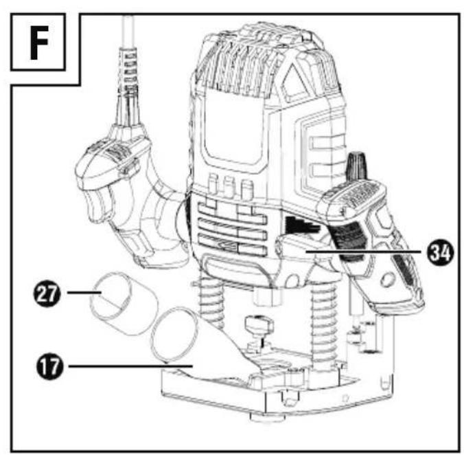
Connecting the dust extraction adapter
Fit the dust extraction adapter onto the holes provided for the dust extraction adapter 9a.
Screw the screw into the underside of the base plate
Attach an approved dust and sawdust extractor to the dust extraction adapter (see fig. F).
Reducer
Connecting
Push the reduce into the dust extraction adapter 17
Push the hose of a suitable of vacuum cleaning appliance (e.g. a workshop vacuum) onto the reducer 27.
Removal
Pull the hose of the vacuum cleaner off the reducer 27.
Remove the reduce.
Changing the collet chuck
NOTE
All of the cutters in the supplied cutter set are equipped with an 8 mm shank. Use the pre-assembled collet chuck (8 mm) with them. When using milling cutters with a 6 mm shank, replace the collet chuck as described below.
Press the spindle locking button and hold it down.
Undo the union nut anticlockwise with the open-endedspanner 24 until the collet chuck 5 (8 mm) can be removed.
Fit the collet chuck19 (6 mm).
ATTENTION! Do not tighten the union nut 5 with the open-ended spanner 24 unless a milling tool is fitted. Otherwise, the collet chuck may be damaged.
Release the spindle locking button.
Fitting the rip fence
Undo the wing screw for the sliding rods.
Push the sliding rod into the corresponding openings next to the wing screws. Retighten the wing screws for the sliding rods.
Setting up
Switching on and off
Switching on
Press the safety lock-out and hold it down.
Press the ON/OFF switch. Once the machine is running, you can release the safety lock-out 3
Switching off
Release the ON/OFF switch4.
Preselecting the rotation speed
Set the required speed using the adjusting wheel for speed preselection 1. 1 - 2 = low speed 3 - 4 = average speed 5 - 7 = high speed
Setting the milling depth
Make sure that the clamping lever is locked. If it is released, turn it anticlockwise until it is locked.
Place the appliance onto the workpiece.
Rotate the step stop until it engages in the lowest position (0 mm). The depth stop now in line with the lowest position (0 mm).
Undo the locking screw.
Release the clamping lever by turning it clockwise and pushing the appliance downwards until the milling machine is touching the surface of the workpiece.
Lock the clamping level by turning it anticlockwise.
Slide the depth stop4 downwards until it reaches the lowest position (0mm) of the step stop 11
Set the depth stop to the desired milling depth, tighten the locking screw 13
NOTE
The values shown on thening depth adjustment scale 15 do not correspond to the actual milling depth. It should always be set relative to a selected point on the milling depth adjustment scale 15
Now, release the clamping lever and raise the appliance again.
Check the milling depth by means of a practical test.
Re-adjusting the milling depth
The milling depth can be readjusted using the dial 16.
Release the clamping level by turning it clockwise and pushing the appliance downwards until the depth stop 14 on the step stop 11 reached.
Lock the clamping leve34 by turning it anticlockwise.
Undo the locking screw. Use the dial 1b adjust the milling depth adjustment scale 15 so that you can set the exact zero point, for example. Retighten the locking screw 13.
Release the clamping level by turning it clockwise and raise the appliance again. Check the milling depth by means of another practical test.
Setting the milling depth with the step stop
NOTE
The step stop can be used for greater milling depths in several stages with less chip removal.
Set the desired milling depth to the lowest step (0mm) of the step stop 1 (as described above).
Then set the higher levels for the first machining steps.
Check the milling depth by means of a practical test.
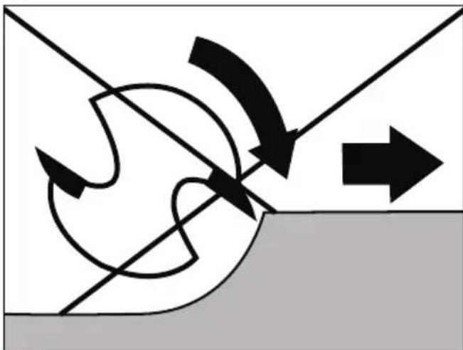
Milling direction
The milling process must always be carried out against the direction of rotation of the milling cutter (reverse rotation). ATTENTION: When milling in the direction of rotation (synchronous running), the power tool can be ripped out of your hand.

Milling operation
Adjust the desired milling depth as described above.
Place the appliance onto the workpiece and switch it on.
Release the clamping levels by turning it clockwise and pushing the appliance downwards until the depth stop 14 sits on the step stop 11.
Lock the appliance by turning the clamping lever 34 anticlockwise.
Carry out the milling process at a uniform speed and contact pressure.
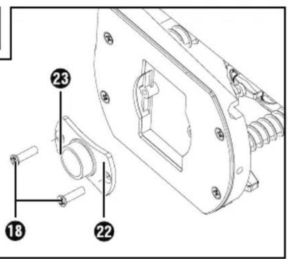
Fitting the copy sleeve
Fit the copy sleeve into the skid plate 10 from below.
Fasten the copy sleeve onto the base plate using the two screws of the dust extraction adapter.
Ensure that you insert the copy sleeve 2the right way around - the race must be facing downwards (see fig. C).
Milling with the copy sleeve
NOTE
The template must be at least as high as the race of the copy sleeve
- Select a smaller cutter than the inner diameter of the copy sleeve.
You can use a copy sleeve to transfer templates onto the workpiece.
Place the router with the copy sleeve on the template.
Release the clamping leve64 by turning it clockwise and lower the appliance until the previously set milling depth is reached.
Now guide the appliance around the template with the copy sleeve protruding. Do not exert excessive pressure when working.
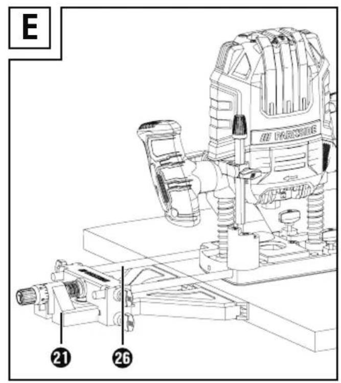
Milling with the rip fence
Push the rip fence according to the required dimension into the guide rails on the base plate and tighten the locking screws.
Place the rip fence onto the edge of the workpiece (see Fig. E).
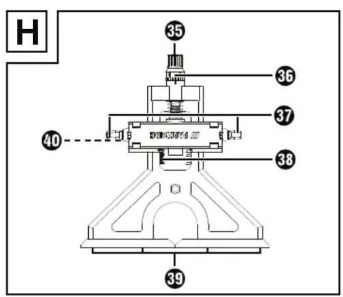
Adjusting the rip fence (fig. H)
Changing the width of the sliding jaws
Loosen the screws for the sliding jaws with a standard Phillips screwdriver (not supplied).
Move the sliding jaws as desired.
Retighten the screws for the sliding jaws.
Fine adjustment of the rip fence
Undo the fixing wing screw.
Turn the did to set the desired distance. One turn corresponds to 1 mm. You can also read the distance on the scale to set values of less than 1 mm, you can orient yourself using the freely rotating scale ring
Retighten the fixing wing screw.
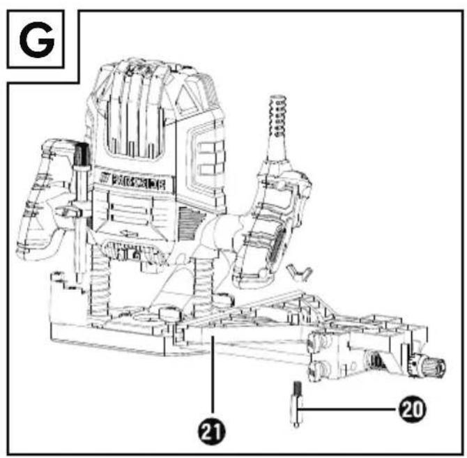
Milling with a compass
To do this, slide the rip fence turned by 180^ (see fig. G) into the guide rails on the base plate according to the required dimension.
Tighten the locking screw
Set the centring point into the rip fence 21 and tighten it using the wing screw (see fig. G). Counter the centring point 20 to tighten it using the oblong hole of the open-ended spanner 24
Stab the centring point into the marked centre point of a circle.
Check the setting by means of a practical test.
Maintenance and cleaning

WARNING! RISK OF INJURY!
Switch the appliance off and remove the power plug before starting any work on the appliance.
The appliance must always be kept clean, dry and free from oil or grease.
Use a soft, dry cloth to clean the housing.

WARNING!
Have the power tool repaired by the service centre or a qualified electrician and only using genuine replacement parts. This will ensure that the safety of the appliance is maintained.
If the connecting cable needs to be replaced, this must be carried out by the manufacturer or an authorised representative in order to avoid safety hazards.
NOTE
- Replacement parts not listed (such as carbon brushes, switches) can be ordered via our service centre.
Disposal

The packaging is made from environmentally friendly material and can be disposed of at your local recycling plant.

Do not dispose of power tools in your normal domestic waste!
European Directive 2012/19/EU requires that worn-out power tools be
collected separately and recycled in an environmentally compatible manner.
Your local community or municipal authorities can provide information on how to dispose of the worn-out appliance.

Dispose of the packaging in an environmentally friendly manner. Note the labelling on the packaging and separate the packaging material
components for disposal if necessary. The packaging material is labelled with abbreviations (a) and numbers (b) with the following meanings: 1-7: plastics, 20-22: paper and cardboard, 80-98: composites.

Your local community or municipal authorities can provide information on how to dispose of the worn-out product.

The product is recyclable, subject to extended producer responsibility and is collected separately.
KompernassHandelsGmbH warranty
Dear Customer,
This appliance has a 3-year warranty valid from the date of purchase. If this product has any faults, you, the buyer, have certain statutory rights. Your statutory rights are not restricted in any way by the warranty described below.
Warranty conditions
The warranty period starts on the date of purchase. Please keep your receipt in a safe place. This will be required as proof of purchase.
If any material or manufacturing fault occurs within three years of the date of purchase of the product, we will either repair or replace the product for you or refund the purchase price (at our discretion).
This warranty service requires that you present the defective appliance and the proof of purchase (receipt) within the three-year warranty period, along with a brief written description of the fault and of when it occurred.
If the defect is covered by the warranty, your product will either be repaired or replaced by us. The repair or replacement of a product does not signify the beginning of a new warranty period.
Warranty period and statutory claims for defects
The warranty period is not prolonged by repairs effected under the warranty. This also applies to replaced and repaired components. Any damage and defects present at the time of purchase must be reported immediately after unpacking. Repairs carried out after expiry of the warranty period shall be subject to a fee.
Scope of the warranty
This appliance has been manufactured in accordance with strict quality guidelines and inspected meticulously prior to delivery.
The warranty covers material faults or production faults. The warranty does not extend to product parts subject to normal wear and tear or to fragile parts which could be considered as consumable parts such as switches or parts made of glass.
The warranty does not apply if the product has been damaged, improperly used or improperly maintained. The directions in the operating instructions for the product regarding proper use of the product are to be strictly followed. Uses and actions that are discouraged in the operating instructions or which are warned against must be avoided.
This product is intended solely for private use and not for commercial purposes. The warranty shall be deemed void in cases of misuse or improper handling, use of force and modifications / repairs which have not been carried out by one of our authorised Service centres.
The warranty period does not apply to
Normal reduction of the battery capacity over time
Commercial use of the product
Damage to or alteration of the product by the customer
Non-compliance with safety and maintenance instructions, operating errors
Damage caused by natural hazards
Warranty claim procedure
To ensure quick processing of your case, please observe the following instructions:
Please have the till receipt and the item number (e.g. IAN 12345) available as proof of purchase.
You will find the item number on the type plate on the product, an engraving on the product, on the front page of the operating instructions (below left) or on the sticker on the rear or bottom of the product.
If functional or other defects occur, please contact the service department listed either by telephone or by e-mail.
You can return a defective product to us free of charge to the service address that will be provided to you. Ensure that you enclose the proof of purchase (till receipt) and information about what the defect is and when it occurred.

You can download these instructions along with many other manuals, product videos and installation software at www.lidl-service.com.
This QR code will take you directly to the Lidl service page (www.lidl-service.com) where you can open your operating instructions by entering the item number (IAN) 359772_2101.
Service
GB Service Great Britain Tel.:08004047657 E-Mail: kompernass@lidl.co.uk
IE Service Ireland Tel.:1890 930 034 (0,08 EUR/Min.,(peak)) (0,06 EUR/Min.,off peak)) E-Mail: kompernass@lidl.ie IAN 359772_2101
Importer
Please note that the following address is not the service address. Please use the service address provided in the operating instructions.
KOMPERNASS HANDELS GMBH
BURGSTRASSE 21
44867 BOCHUM
GERMANY
www.kompernass.com
Translation of the original Conformity Declaration
We, KOMPERNASS HANDELS GMBH, documents officer: Mr. Semi Uguzlu, BURGSTR. 21, 44867 BOCHUM, Germany, hereby declare that this product complies with the following standards, normative documents and EC directives:
Machinery Directive
(2006/42/EC)
Electromagnetic Compatibility
(2014/30/EU)
RoHS Directive
(2011/65/EU)*
- The manufacturer bears the full responsibility for compliance with this conformity declaration. The object of the declaration described above complies with the requirements of the Directive 2011/65/EU of the European Parliament and Council of 8 June 2011 on the limitations of use of certain dangerous substances in electrical and electronic appliances.
Applied harmonised standards
EN 62841-1:2015
EN 62841-2-17:2017
EN 55014-1:2017/A11:2020
EN 55014-2:2015
EN IEC 61000-3-2:2019
EN 61000-3-3:2013/A1:2019
ENIEC63000:2018
Type designation of the machine: Router POF 1200 D3
Year of manufacture: 05-2021
Serial number: IAN 359772_2101
Bochum, 14/05/2021

Semi Uguzlu
- Quality Manager -
The right to effect technical changes in the context of further development is reserved.
Inhaltsverzeichnis
Einleitung 16
OBERFRÄSE POF 1200 D3
Einleitung
KOMPERNASS HANDELS GMBH
BURGSTRASSE 21
44867 BOCHUM
GERMANY
www.kompernass.com
Chere cliente, cher client,
Chere cliente, cher client,
KOMPERNASS HANDELS GMBH
BURGSTRASSE 21
44867 BOCHUM
ALLEMAGNE
www.kompernass.com
Directive relative aux machines
(2006/42/CE)
$$ L _ {P A} = 8 6, 7 \mathrm {d B (A)} $$
Onzekerheid
$$ K _ {p A} = 3 \mathrm {d B} $$
Geluidsvermögensniveau
$$ L _ {W A} = 9 7, 7 \mathrm {d B (A)} $$
Onzekerheid K K
$$ \mathrm {w} _ {\mathrm {A}} = 3 \mathrm {d B} $$
WAARSCHUWING! LETSELGEVAAR!
KOMPERNASS HANDELS GMBH
BURGSTRASSE 21
44867 BOCHUM
DUITSLAND
www.kompernass.com
KOMPERNASS HANDELS GMBH
BURGSTRASSE 21
44867 BOCHUM
NÉMECKO
www.kompernass.com
KOMPERNASS HANDELS GMBH
BURGSTRASSE 21
44867 BOCHUM
NIEMCY
www.kompernass.com
Neurcitosf K K WA = 3 dB
Noste ochranu slachu!
Hodnota emisie vibraciui
Celković hodnoty vibracii (suet vektorov troch smerov) zistovane podla EN 62841:
Vibrácia ruk/ramien a_h = 4,3m / s^2
Neurcitost' K= 1,5 m/s2
UPOZORNENIE
KOMPERNASS HANDELS GMBH
BURGSTRASSE 21
44867 BOCHUM
NEMECKO
www.kompernass.com
Vaeerkjsholder 6/8 mm
Beskyttesesklasse (dbbeltisolring)
Stojemissionsværdi
Usikkerhed K K WA = 3 dB
Baer horevaern!
Hand/armvibration a_h = 4,3m / s^2
KOMPERNASS HANDELS GMBH
BURGSTRASSE 21
44867 BOCHUM
GERMANY
www.kompermass.com
Last Information Update · Stand der Informationen · Version des informations · Stand van de informatie
Stav informaci - Stan informaci - Stav informacion - Estado de las informaciones - Tilstand af information:
05/2021·Ident.-No.:POF1200D3-052021-1
IAN 359772_2101