
PMNF 1350 A1 - Milling machine PARKSIDE - Free user manual and instructions
Find the device manual for free PMNF 1350 A1 PARKSIDE in PDF.

| Product Type | Milling Machine |
| Model | PMNF 1350 A1 |
| Brand | Parkside |
| Power Input | 1350 W |
| Voltage | 230 V ~ 50 Hz |
| No-Load Speed | 250 - 3000 rpm (variable) |
| Spindle Taper | MT2 (Morse Taper 2) |
| Max. Milling Diameter in Steel | 16 mm |
| Max. Drilling Capacity in Steel | 16 mm |
| Table Size | 500 x 120 mm |
| T-Slot Width | 12 mm |
| Base Dimensions (L x W) | 550 x 350 mm |
| Weight | 25 kg |
| Protection Class | IP20 |
| Safety Features | Emergency stop switch, spindle cover, overload protection |
| Main Functions | Milling, drilling, slotting, engraving |
| Supplied Accessories | Collet chuck set (6 pcs), machine vice, wrenches |
| Material | Cast iron base, steel column and table |
| Maintenance | Regular cleaning and lubrication of guide rails; check belt tension |
| Noise Level (LpA) | 85 dB(A) |
| Vibration (ah) | < 2.5 m/s² |
| Spare Parts Availability | Via Parkside service center or online |
Frequently Asked Questions - PMNF 1350 A1 PARKSIDE
User questions about PMNF 1350 A1 PARKSIDE
0 question about this device. Answer the ones you know or ask your own.
Ask a new question about this device
Download the instructions for your Milling machine in PDF format for free! Find your manual PMNF 1350 A1 - PARKSIDE and take your electronic device back in hand. On this page are published all the documents necessary for the use of your device. PMNF 1350 A1 by PARKSIDE.
USER MANUAL PMNF 1350 A1 PARKSIDE
Wall CHaSER PMNF 1350 a1
GB
Wall CHaSER
Operation and Safety Notes
Translation of original operation manual
HU
FalHORONYMaRÓ
Before reading, unfold the page containing the illustrations and familiarise yourself with all functions of the device.
PL
GB Operation and Safety Notes Page 5
| PL Wskazówki dotyczące obstugi i bezpieczeństwa Strona 15 | |||
| HU Kezelési és biztonsági utalások Oldal 27 | |||
| SI Navodila za upravljanje in varnostna opozorila | Stran | 39 | |
| CZ | Pokyny pro obsluhu a bezpečnostní pokyny | Strana 49 | |
| SK | Pokyny pre obsluhu a bezpečnostné pokyny | Strana 59 | |
| DE/AT/CH | Bedienungs- und Sicherheitshinweise | Seite 69 | |
Introduction
Intended use....Page 6
Device description......Page 6
Scope of delivery Page 6
Technical Data Page 6
General power tool safety warnings
-
Work area safety Page 7
-
Electrical safety....Page 7
-
Personal safety Page 7
-
Power tool use and care....Page 8
-
Service Page 8
Cut-off machine safety warnings......Page 8
Further safety instructions for abrasive cutting-off operations....Page 10
Supplementary Instructions......Page 10
Original accessories/tools Page 11
Start-up
Setting the groove depth....Page 11
Installing the dust extraction adapter....Page 11
Operation
Switching ON/OFF......Page 11
Installing and adjusting the cutting width of the diamond cutting discs....Page 11
Handling the wall chaser....Page 11
Maintenance and Cleaning Page 12
Warranty Page 12
Translation of the original declaration of conformity / Manufacturer Page 13
Wall chaser PMNF 1350 A1
●Introduction
We congratulate you on the purchase of your new device. You have chosen a high quality product. The instructions for use are part of the product. They contain important information concerning safety, use and disposal. Before using the product, please familiarise yourself with all of the safety information and instructions for use. Only use the unit as described and for the specified applications. If you pass the product on to anyone else, please ensure that you also pass on all the documentation with it.
Intendeduse
The wall chaser (normative cut-off machine), in the following also referred to as device, in conjunction with an approved industrial dust extractor, is intended to cut or slit primarily mineral materials, e.g. concrete or masonry when firmly applied with the guide sled without the use of water. Any other uses, and / or modifications to the appliance, are deemed to be improper usage and may result in serious physical injury. Not for commercial applications.
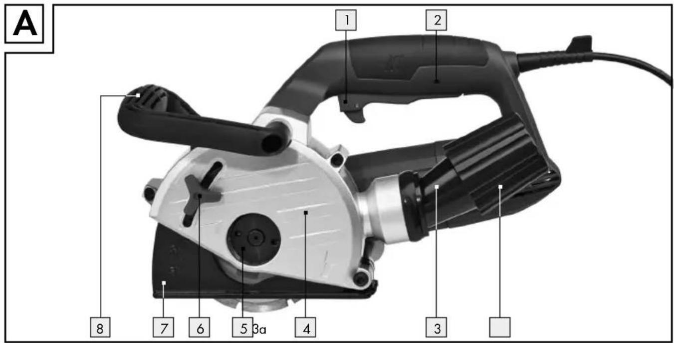
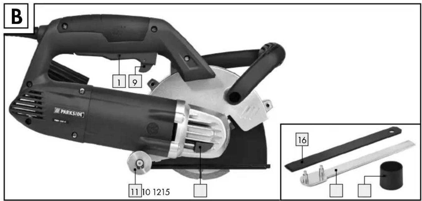
●Devidedescription (see Fig. A–D)
1 ON-/OFF-switch
2 Handle
3 Dust extraction adapter
3a Union nut
4 Protective cover
5 Adapter flange (with thread)
6 Depth stop set screw
7 Depth stop
8 Additional handle
9 Switch lock
10 Spindle lock
11 Roller
12 Reducer
13 Centring flange
14 Spacers
15 Face pin wrench
16 Chisel
- Scope of delivery
1 Wall chaser
2 Cutting discs (preinstalled)
1 Face pin wrench
1 Extraction adapter (preinstalled)
1 Reducer
(for use with the extraction adapter and a size 32 mm vacuum hose)
1 Chisel
1 Instructions for use
●TechnicalData
Mains voltage: 230V\~50Hz
Power input: 1350W
Rated no load speed: 9000 min ^-1
Disc ø: 125 mm
Mounting hole: 22.2 mm
Groove depth: 0-30 mm
Groove width: 8-26 mm
Thread: M14
Protection class: II/回
Weight: approx. 4.05 kg
Noise and vibration
Noise and vibration ratings were determined according to EN 60745.
Noise level L_pA : 97.6 dB(A)
Uncertainty K_pA : 3 dB
Sound power level LWA: 108.6 dB(A)
Uncertainty KWA: 3 dB
Wear ear protection.
Exposure to noise can cause hearing loss.
The total vibration (vector sum of three directions) is calculated in accordance with EN 60745.
Declaration of vibration emission value
(Cutting concrete slab):
Main Handle: 6.417 m/s ^2
Auxiliary Handle: 4.258 m/s ^4
Uncertainty K = 1.5 m/s ^2
WARNING!
The vibration emission value specified was measured according to a standardised testing method and may vary depending on the method the power tool is being used, and in exceptions be higher than the specified value.
The vibration emission value specified can be used to compare power tools.
The vibration emission value specified can also serve as a preliminary assessment of the impact.
Try to keep the vibration loads as low as possible. Measures to reduce the vibration load are, e.g. wearing gloves and limiting the working time. Wherein all states of operation must be included (e.g. times when the power tool is switched off and times where the power tool is switched on but running without load).
● General power tool safety warnings

WARNING! Read all safety warnings and all instructions. Fail-
ure to follow the warnings and instructions
may result in electric shock, fire and / or serious injury.
Save all warnings and instructions for future reference.
The term "power tool" in the warnings refers to your mains-operated (corded) power tool or battery-operated (cordless) power tool.
1. Work area safety
a) Keep work area clean and well lit. Cluttered or dark areas invite accidents.
b) D not operate power tools in explosive atmospheres, such as in the presence of flammable liquids, gases or dust.
Power tools create sparks which may ignite the dust or fumes.
c) Keep children and bystanders away while operating a power tool. Distractions can cause you to lose control.
2. Electrical safety
a) Power tool plugs must match the outlet. Never modify the plug in any way. Do not use any adapter plugs with earthed (grounded) power tools. Unmodified plugs and matching outlets will reduce risk of electric shock.
b) Avoid body contact with earthed or grounded surfaces, such as pipes, radiators, ranges and refrigerators.
There is an increased risk of electric shock if your body is earthed or grounded.
c) Do not expose power tools to rain or wet conditions. Water entering a power tool will increase the risk of electric shock.
d) Do not abuse the cord. Never use the cord for carrying, pulling or unplugging the power tool. Keep cord away from heat, oil, sharp edges or moving parts. Damaged or entangled cords increase the risk of electric shock.
e) When operating a power tool outdoors, use an extension cord suitable for outdoor use. Use of a cord suitable for outdoor use reduces the risk of electric shock.
f) If operating a power tool in a damp location is unavoidable, use a residual current device (RCD) protected supply. Use of an RCD reduces the risk of electric shock.
3. Personal safety
a) Stay alert, watch what you are doing and use common sense when operating a power tool. Do not use a power tool while you are tired or under the influence of drugs, alcohol or medication. A moment of inattention while operating power tools may result in serious personal injury.
b) Use personal protective equipment. Always wear eye protection. Protective equipment such as dust mask, non-skid safety shoes, hard hat, or hearing protection used for appropriate conditions will reduce personal injuries.
c) Prevent unintentional starting. Ensure the switch is in the off-position before connecting to power source and / or battery pack, picking up or carrying the tool. Carrying power tools with your finger on the switch or energising power tools that have the switch on invites accidents.
d) Remove any adjusting key or wrench before turning the power tool on. A wrench or a key left attached to a rotating part of the power tool may result in personal injury.
e) Do not overreach. Keep proper footing and balance at all times. This enables better control of the power tool in unexpected situations.
f) Dress properly. Do not wear loose clothing or jewellery. Keep your hair, clothing and gloves away from moving parts. Loose clothes, jewellery or long hair can be caught in moving parts.
g) If devices are provided for the connection of dust extraction and collection facilities, ensure these are connected and properly used. Use of dust collection can reduce dust-related hazards.
4. Power tool use and care
a) Do not force the power tool. Use the correct power tool for your application.
The correct power tool will do the job better and safer at the rate for which it was designed.
b) Do not use the power tool if the switch does not turn it on and off. Any power tool that cannot be controlled with the switch is dangerous and must be repaired.
c) Disconnect the plug from the power source and / or the battery pack from the power tool before making any adjustments, changing accessories, or storing power tools. Such preventive safety measures reduce the risk of starting the power tool accidentally.
d) Store idle power tools out of the reach of children and do not allow persons unfamiliar with the power tool or these instructions to operate the power tool.
Power tools are dangerous in the hands of un-trained users.
e) Maintain power tools. Check for misalignment or binding of moving parts, breakage of parts and any other condition that may affect the power tool's operation. If damaged, have the power tool repaired before use. Many accidents are caused by poorly maintained power tools.
f) Keep cutting tools sharp and clean.
Properly maintained cutting tools with sharp cutting edges are less likely to bind and are easier to control.
g) Use the power tool, accessories and tool bits etc. in accordance with these instructions, taking into account the working conditions and the work to be performed. Use of the power tool for operations different from those intended could result in a hazardous situation.
5. Service
a) Have your power tool serviced by a qualified repair person using only identical replacement parts. This will ensure that the safety of the power tool is maintained.
• Cut-off machine safety warnings
a) The guard provided with the tool must be securely attached to the power tool and positioned for maximum safety, so the least amount of wheel is exposed towards the operator. Position yourself and bystanders away from the plane of the rotating wheel. The guard helps to protect operator from broken wheel fragments and accidental contact with wheel.
b) Only use diamond-tip cutting discs with your power tool. Just because an accessory can be attached to your power tool, it does not assure safe operation.
c) The rated speed of the accessory must be at least equal to the maximum speed
marked on the power tool. Accessories running faster than their rated speed can break and fly apart.
d) Wheels must be used only for recommended applications. For example: do not grind with the side of cut-off wheel. Abrasive cut-off wheels are intended for peripheral grinding, side forces applied to these wheels may cause them to shatter.
e) Always use undamaged wheel flanges that are of correct diameter for your selected wheel. Proper wheel flanges support the wheel thus reducing the possibility of wheel breakage.
f) Do not use worn down reinforced wheels from larger power tools. Wheels intended for a larger power tool are not suitable for the higher speed of a smaller tool and may burst.
g) The outside diameter and the thickness of your accessory must be within the capacity rating of your power tool. In-correctly sized accessories cannot be adequately guarded or controlled.
h) The arbour size of wheels and flanges must properly fit the spindle of the power tool. Wheels and flanges with arbour holes that do not match the mounting hardware of the power tool will run out of balance, vibrate excessively and may cause loss of control.
i) Do not use damaged wheels. Before each use, inspect the wheels for chips and cracks. If power tool or wheel is dropped, inspect for damage or install an undamaged wheel. After inspecting and installing the wheel, position yourself and bystanders away from the plane of the rotating wheel and run the power tool at maximum no load speed for one minute. Damaged wheels will normally break apart during this test time.
j) Wear personal protective equipment. Depending on application, use face shield, safety goggles or safety glasses. As appropriate, wear dust mask, hearing protectors, gloves and shop apron capable of stopping small abrasive or
workpiece fragments. The eye protection must be capable of stopping flying debris generated by various operations. The dust mask or respirator must be capable of filtrating particles generated by your operation. Prolonged exposure to high intensity noise may cause hearing loss.
k) Keep bystanders a safe distance away from work area. Anyone entering the work area must wear personal protective equipment. Fragments of workpiece or of a broken wheel may fly away and cause injury beyond immediate area of operation.
I) Hold the power tool by insulated gripping surfaces only, when performing an operation where the cutting accessory may contact hidden wiring or its own cord. Cutting accessory contacting a "live" wire may make exposed metal parts of the power tool "live" and could give the operator an electric shock.
m) Position the cord clear of the spinning accessory. If you lose control, the cord may be cut or snagged and your hand or arm may be pulled into the spinning wheel.
n) Never lay the power tool down until the accessory has come to a complete stop. The spinning wheel may grab the surface and pull the power tool out of your control.
Do not run the power tool while carrying it at your side. Accidental contact with the spinning accessory could snag your clothing, pulling the accessory into your body.
p) Regularly clean the power tool's air vents. The motor's fan will draw the dust inside the housing and excessive accumulation of powdered metal may cause electrical hazards.
q) Do not operate the power tool near flammable materials. Sparks could ignite these materials.
r) Do not use accessories that require liquid coolants. Using water or other liquid coolants may result in electrocution or shock.
● Further safety instructions for abrasive cutting-off operations
Kickback and related warnings
Kickback is a sudden reaction to a pinched or snagged rotating wheel. Pinching or snagging causes rapid stalling of the rotating wheel which in turn causes the uncontrolled power tool to be forced in the direction opposite of the wheel's rotation at the point of the binding.
For example, if an abrasive wheel is snagged or pinched by the workpiece, the edge of the wheel that is entering into the pinch point can dig into the surface of the material causing the wheel to climb out or kick out. The wheel may either jump toward or away from the operator, depending on direction of the wheel's movement at the point of pinching. Abrasive wheels may also break under these conditions. Kickback is the result of power tool misuse and / or incorrect operating procedures or conditions and can be avoided by taking proper precautions as given below.
a) Maintain a firm grip on the power tool and position your body and arm to allow you to resist kickback forces. Always use auxiliary handle, if provided, for maximum control over kickback or torque reaction during start-up. The operator can control torque reactions or kickback forces, if proper precautions are taken.
b) Never place your hand near the rotating accessory. Accessory may kickback over your hand.
c) Do not position your body in line with the rotating wheel. Kickback will propel the tool in direction opposite to the wheel's movement at the point of snagging.
d) Use special care when working corners, sharp edges etc. Avoid bouncing and snagging the accessory. Corners, sharp edges or bouncing have a tendency to snag the rotating accessory and cause loss of control or kickback.
e) Do not attach a saw chain, woodcarving blade, segmented diamond wheel
with a peripheral gap greater than 10 mm or toothed saw blade. Such blades create frequent kickback and loss of control.
f) Do not "jam" the wheel or apply excessive pressure. Do not attempt to make an excessive depth of cut. Over-stressing the wheel increases the loading and susceptibility to twisting or binding of the wheel in the cut and the possibility of kickback or wheel breakage.
g) When wheel is binding or when interrupting a cut for any reason, switch off the power tool and hold the power tool motionless until the wheel comes to a complete stop. Never attempt to remove the wheel from the cut while the wheel is in motion otherwise kick-back may occur. Investigate and take corrective action to eliminate the cause of wheel binding.
h) Do not restart the cutting operation in the workpiece. Let the wheel reach full speed and carefully re-enter the cut. The wheel may bind, walk up or kickback if the power tool is restarted in the workpiece.
i) Support panels or any oversized workpiece to minimize the risk of wheel pinching and kickback. Large workpieces tend to sag under their own weight. Supports must be placed under the workpiece near the line of cut and near the edge of the workpiece on both sides of the wheel.
Use extra caution when making a "pocket cut" into existing walls or other blind areas. The protruding wheel may cut gas or water pipes, electrical wiring or objects that can cause kickback.
●SupplementaryInstructions
Approved cutting wheel designs: diamond set, disc diameter 125 mm, disc thickness max. 2.2 mm
■ Always wear a dust mask!
■ Always wear ear protection!
• Original accessories/tools
- Use only the accessories and attachments detailed in the operating instructions, or those which are compatible with the device.
- Start-up
- Setting the groove depth
□ Loosen set screw.
Set the depth stop to the desired depth.
Tighten set screw.
- Installing the dust extraction adapter
☐ Slide the pegs of the extraction adapter 3 into the slots of the dust extraction connection.
□ Turn the extraction adapter 3 to lock.
□ Loosen union nut 3a.
☐ Insert the tube of the extraction unit far enough into the opening on the union nut 3a.
□ Tighten union nut 3a.
Operation
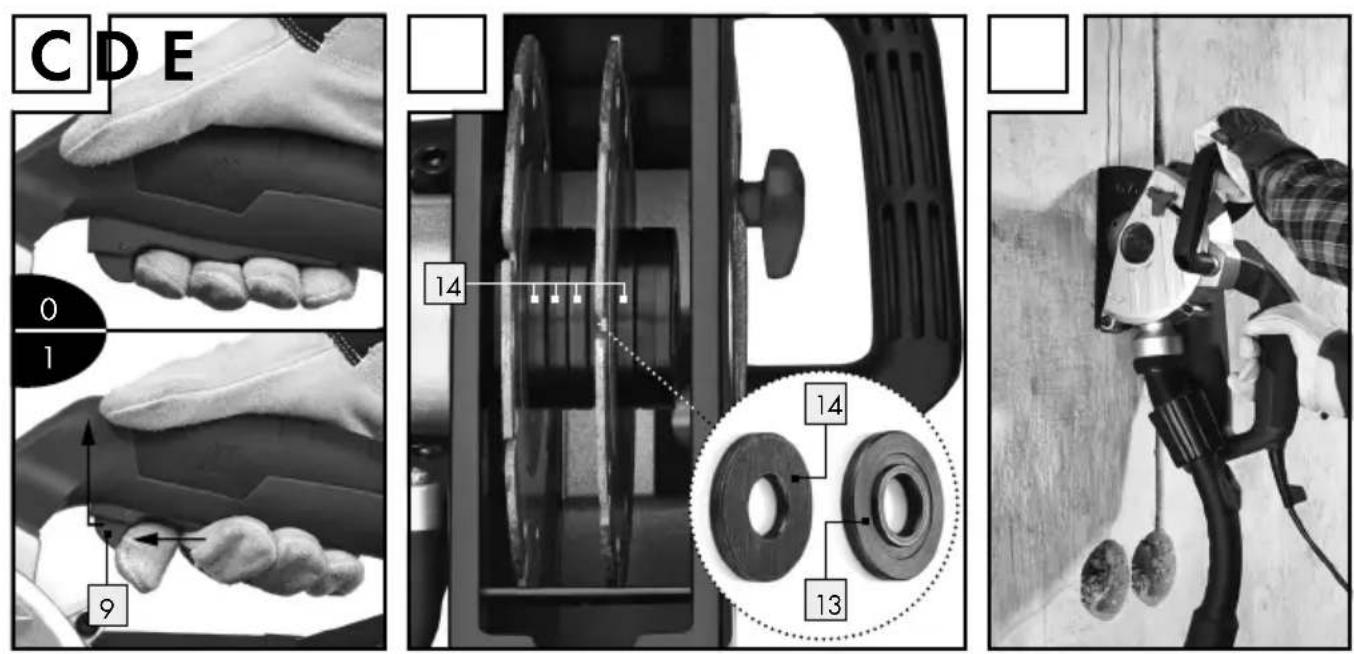
- Switching ON/OFF
NOTE: Always switch on the device before bringing into contact with the material and only then apply the device to the work piece. The wall grinder features electronic smooth start-up. The motor's start-up is delayed.
Switching the unit on:
□ Activate the switch lock (see Fig. C). Then press the ON / OFF switch 1.
Switching the device off:
Release the ON / OFF switch.
• Installing and adjusting the cutting width of the diamond cutting discs
Loosen set screw.
Slide the depth stop up.
Press and hold the spindle lock.
Use the face pin wrend5 to loosen the adapter flange 5.
Remove the adapter flange.
Set the desired cutting width with the number of spacers 14. Be sure to use the centring flange 13 as the top spacer.
NOTE: You may choose from various spacers. Please note, the total number of spacers between the cutting discs and the thickness of the cutting discs yield the groove width.
Tighten the adapter flange with the face pin wrench 15. When doing so, hold the spindle lock.
NOTE: When setting a cutting width smaller than the maximum, you must use the spacers on the clamping collar side, as the clamping collar alone cannot secure the discs due to the thread length on the spindle (see. Fig. D).
NOTE: Always replace diamond cutting discs in pairs.
● Handling the wall chaser (see Fig. E)
ATTENTION! This device is only suitable for dry cuts!
Use a cable detector to check walls for hidden electrical-, gas- and water lines before using the wall chaser.
Select the desired groove width.
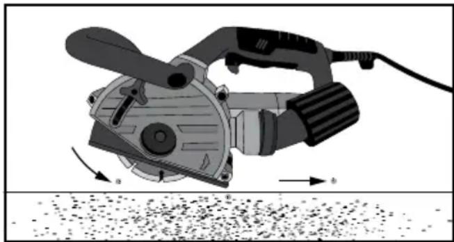
□ Apply the roller of the device onto the brick wall.
Now switch on the device and immerse into the brick wall until the depth stop 7 touches.
Now cut the groove into the brick wall, noting the cutting direction. The device must be rotating in the opposite direction. The device can otherwise erratically be pushed out of the cut.
natural_image
Illustration of a power tool cutting through a pile of material (no text or symbols)At the end of the groove swing the device out of the groove and only then switch off the device.
Now remove the ridge created between the two grooves with a chisel 16.
Do not work on materials containing asbestos!
● Maintenance and Cleaning
WARNING! RISK OF INJURY! Switch the device off and pull the plug out of the mains socket before carrying out any work on the device.
□ Always keep the device clean, dry and free of oil or grease.
☐ Use a dry cloth to clean the housing.
WARNING! If the connection cable needs to be replaced, this repair must be performed by the manufacturer or a representative to prevent safety hazards.
Grinding tools must be handled and transported with care. Grinding tools have to be stored in such a way that they are not exposed to mechanical damage or damaging environmental influences.
Note: Spare parts not listed (e.g. carbon brushes, switches) can be ordered through our call centre.
●Warranty
The warranty for this appliance is for 3 years from the date of purchase. The appliance has been manufactured with care and meticulously examined before delivery. Please retain your receipt as proof of purchase. In the event of a warranty claim, please make contact by telephone
with our Service Department. Only in this way can a post-free despatch for your goods be assured.
The warranty covers only claims for material and manufacturing defects, but not for transport damage, for wearing parts or for damage to fragile components, e.g. buttons or batteries. This product is for private use only and is not intended for commercial use.
The warranty is void in the case of abusive and improper handling, use of force and internal tampering not carried out by our authorized service branch. Your statutory rights are not restricted in any way by this warranty.
The warranty period will not be extended by repairs made unter warranty. This applies also to replaced and repaired parts. Any damage and defects extant on purchase must be reported immediately after unpacking the appliance, at the latest, two days after the purchase date. Repairs made after the expiration of the warranty period are subject to payment.
GB Service Great Britain Tel.: 0871 5000 720 (0.10 GBP/Min.)
e-mail: kompernass@lidl.co.uk
IAN 102830
- Disposal

The packaging is wholly composed of environmentally-friendly materials that can be disposed of at a local recycling centre.

Do not dispose of electric tools in the household waste!
In accordance with European Directive 2012/19/EU (covering waste electrical and electronic equipment) and its transposition into national legislation, worn out electrical power tools must be collected separately and taken for environmentally compatible recycling.
Contact your local refuse disposal authority for more details of how to dispose of your worn out electrical devices.
● Translation of the original declaration of conformity / Manufacturer CE
We, KOMPERNASS HANDELS GMBH, the person responsible for documents: Mr Semi Uguzlu, BURGSTRASSE 21, 44867 BOCHUM, GERMANY, hereby declare that this product complies with the following standards, normative documents and EU directives:
Machinery Directive (2006/42/EC)
EU Low Voltage Directive (2006/95/EC)
Electromagnetic Compatibility (2004/108/EC)
RoHS Directive (2011/65/EU)
Applicable harmonized standards
EN 60745-1/A11:2010
EN 60745-2-22:2011
EN 55014-1/A2:2011
EN 55014-2/A2:2008
EN 61000-3-2/A2:2009
EN 61000-3-3:2008
Type / Device description:
Wall chaser PMNF 1350 A1
Date of manufacture (DOM): 10–2014
Serial number: IAN 102830
Bochum, 31.10.2014

Semi Uguzlu
- Quality Manager -
We reserve the right to make technical modifications in the course of further development.
Wstep
natural_image
Illustration of a power tool cutting through a pile of material (no text or symbols)Date of manufacture (DOM): 10-2014
natural_image
Illustration of a power tool cutting into a surface with motion arrows (no text or symbols)Date of manufacture (DOM): 10-2014
Negotovost K_pA : 3 dB
Raven hrupa LWA: 108,6 dB(A)
Negotovost Kwa: 3 dB
natural_image
Illustration of a power tool cutting through a pile of material (no text or symbols)Semi Uguzlu
- Vodja kakovosti -
Pridržujemo si pravico do tehničnih sprememb.
SI
080080917
Garancijski list
natural_image
Illustration of a power tool cutting through a pile of material (no text or symbols)Date of manufacture (DOM): 10-2014
natural_image
Illustration of a power tool cutting through a pile of material (no text or symbols)natural_image
Illustration of a power tool cutting through a pile of material (no text or symbols)KOMPERNASS HANDELS GMBH
BURGSTRASSE21
44867BOCHUM
GERMANY


- Wall CHaSER PMNF 1350 a1
- Wall CHaSER
- FalHORONYMaRÓ
- Introduction
- General power tool safety warnings
- Start-up
- Operation
- Maintenance and Cleaning Page 12
- Warranty Page 12
- Translation of the original declaration of conformity / Manufacturer Page 13
- ●Introduction
- Intendeduse
- ●Devidedescription (see Fig. A–D)
- - Scope of delivery
- ●TechnicalData
- Noise and vibration
- Wear ear protection.
- WARNING!
- ● General power tool safety warnings
- WARNING! Read all safety warnings and all instructions. Fail-
- Save all warnings and instructions for future reference.
- Work area safety
- Electrical safety
- Personal safety
- Power tool use and care
- Service
- • Cut-off machine safety warnings
- ● Further safety instructions for abrasive cutting-off operations
- Kickback and related warnings
- ●SupplementaryInstructions
- Switching the unit on:
- Switching the device off:
- ● Maintenance and Cleaning
- ●Warranty
- - Disposal
- ● Translation of the original declaration of conformity / Manufacturer CE
- Applicable harmonized standards
- Type / Device description:
- Date of manufacture (DOM): 10–2014
- Wstep
- Garancijski list
- Date of manufacture (DOM): 10-2014
- KOMPERNASS HANDELS GMBH
Brand : PARKSIDE
Model : PMNF 1350 A1
Category : Milling machine