
CT SW10 - Subwoofer BOWERS & WILKINS - Free user manual and instructions
Find the device manual for free CT SW10 BOWERS & WILKINS in PDF.

| Product type | Passive subwoofer |
| Brand | Bowers & Wilkins |
| Model | CT SW10 |
| Recommended amplifier | SA1000 (dedicated subwoofer amplifier) |
| Input connections | Screw terminals (2 pairs) and Neutrik Speakon 4-pole connector |
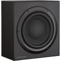
| Front grille | Removable, magnetic attachment |
| Supplied feet | 4 M6 metal spikes, 4 M6 rubber feet, 4 lock nuts |
| Use | Home theater and 2-channel audio |
| Maintenance | Dust with a soft dry cloth; clean grille with a clothes brush |
| Safety | Do not expose to moisture, heat sources, or liquids; disconnect during storms |
| Warranty | 5 years for the speaker (excluding electronic components) |
| Included accessories | 1 Neutrik Speakon 2-pole connector, spikes and feet |
| Break-in period | Approximately 15 hours of normal use for optimal performance |
| Compatibility | Designed for use with the SA1000 amplifier |
| Magnetic field | Keep at least 50 cm away from sensitive devices |
Frequently Asked Questions - CT SW10 BOWERS & WILKINS
User questions about CT SW10 BOWERS & WILKINS
0 question about this device. Answer the ones you know or ask your own.
Ask a new question about this device
Download the instructions for your Subwoofer in PDF format for free! Find your manual CT SW10 - BOWERS & WILKINS and take your electronic device back in hand. On this page are published all the documents necessary for the use of your device. CT SW10 by BOWERS & WILKINS.
USER MANUAL CT SW10 BOWERS & WILKINS
Figure 2
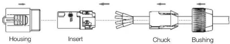
Neutrik Speakon Connector NL2FC
Ring Insert + Chuck Bushing
Neutrik Speakon Connector NL4FC
NL2FC NL4FC
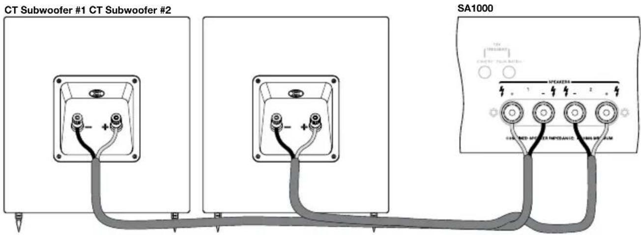
Figure 4

Figure 5
Contents
English
Installation and Setup Manual .........3 Limited Warranty....8
Français
EU Declarations of Conformity ....99-100 Technical Specifications....101-104
English Installation and Setup Manual
Important Safety Instructions
- Read these instructions.
- Keep these instructions.
- Heed all warnings.
- Follow all instructions.
- Do not use this apparatus near water.
- Clean only with dry cloth.
- Do not block any ventilation openings. Install in accordance with the manufacturer's instructions.
- Do not install near any heat sources such as radiators, heat registers, stoves, or other apparatus (including amplifiers) that produce heat.
- Do not defeat the safety purpose of the polarized or grounding-type plug. A polarized plug has two blades with one wider than the other. A grounding type plug has two blades and a third grounding prong. The wide blade or the third prong are provided for your safety. If the provided plug does not fit into your outlet, consult an electrician for replacement of the obsolete outlet.
- Protect the power cord from being walked on or pinched particularly at plugs, convenience receptacles, and the point where they exit from the apparatus.
- Only use attachments/accessories specified by the manufacturer.
- Use only with the cart, stand, tripod, bracket, or

table specified by the manufacturer, or sold with the apparatus. When a cart is used, use caution when moving the cart/apparatus combination to avoid injury from tip-over.
- Unplug this apparatus during lightning storms or when unused for long periods of time.
- Refer all servicing to qualified service personnel. Servicing is required when the apparatus has been damaged in any way, such as power-supply cord or plug is damaged, liquid has been spilled or objects have fallen into the apparatus, the apparatus has been exposed to rain or moisture, does not operate normally, or has been dropped.
- Do not expose this apparatus to dripping or splashing and ensure that no objects filled with liquids, such as vases, are placed on the apparatus.
-
To completely disconnect this apparatus from the AC Mains, disconnect the power supply cord plug from the AC receptacle.
-
The mains plug of the power supply cord shall remain readily operable.
- Do not expose batteries to excessive heat such as sunshine, fire or the like.
The lightning flash with arrowhead symbol within an equilateral triangle, is intended to alert the user to the presence of uninsulated "dangerous voltage" within the product's enclosure that may be of sufficient magnitude to constitute a risk of electric shock to persons.

The exclamation point within an equilateral triangle is intended to alert the user to the presence of important operating and maintenance (servicing) instructions in the literature accompanying the product.
WARNING: To reduce the risk of fire or electric shock, do not expose this apparatus to rain or moisture.
- When replacement parts are required, be sure the service technician has used replacement parts specified by the manufacturer or have the same characteristics as the original part. Unauthorised substitutions may result in fire, electric shock or other hazards.
- Check that there are no cables under the carpet that may be damaged by the spike feet. Do not walk the product on the spike feet as this may cause them to become detached from the cabinet and cause damage. Take care not to impale yourself with the spike feet.
- For continued protection against fire hazard, use fuses only of the correct type and rating. Mains fuses are located inside the appliance as well as on its back panel. Replacement of the internal fuse should be entrusted to an authorised operative. User-replaceable fuse types are shown in the specification.
- Isolation of the appliance from the power supply is by means of removal of the power cord from the rear of the appliance or removal of the power cord from the wall power outlet. Either the wall outlet or the rear of the appliance must remain freely accessible at all times while the apparatus is in use.
- This product should be operated only from the type of power source indicated by the marking adjacent to the power cord entry. If you are not sure of the type of power supply to your home, consult your product dealer or local power company.
- Do not overload wall outlets, extension cords or integral convenience receptacles, as this can result in a risk of fire or electric shock.
- Magnetic fields - The product creates a stray static magnetic field. Do not place any object that may be damaged by this magnetic field (eg
cathode ray tube televisions or computer monitors, audio and video tapes and swipe cards) within 0.5m (2 feet) of the appliance. The appliance may cause distortion of cathode ray tube images beyond this distance. LCD and Plasma screens are not affected.
- Mounting - Do not place this product on an unstable stand, tripod, bracket or table. The product may fall causing serious injury and serious damage. Any mounting of the product should follow the manufacturer's instructions.
Do not expose the device to rain, use it near water or in damp or wet conditions, or place containers on it containing liquids which might spill into any openings.
When setting up the device, make sure that the AC outlet you are using is easily accessible. If some trouble or malfunction occurs, immediately turn off the power switch and disconnect the plug from the outlet. Even when the power switch is turned off, electricity is still flowing to the product at the minimum level. When you are not using the device for a long time, make sure to unplug the power cord from the wall AC outlet.
Introduction
Dear customer,
Thank you for choosing Bowers & Wilkins. Please read this manual fully before unpacking and installing the product. It will help you to optimise its performance. B&W maintains a network of dedicated distributors in over 60 countries who will be able to help you should you have any problems your dealer cannot resolve.
Environmental Information

All B&W products are designed to comply with international directives on the Restriction of Hazardous Substances
(RoHS) in electrical and electronic equipment and the disposal of Waste Electrical and Electronic Equipment (WEEE). These symbols indicate compliance and that the products must be appropriately recycled or processed in accordance with these directives. Consult your local waste disposal authority for guidance.
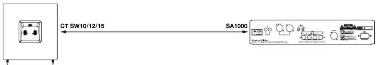
This manual covers the CT SW10, CT SW12 and CT SW15 subwoofoers and their matching SA1000 automated rack mount power amplifier.
Carton Contents
Check subwoofer carton for:
1 Accessory pack containing:
4 x M6 spike feet
4×M6 rubber feet
4 x Lock nuts (10mm across flats)
1 x Two-pole Neutrik Speakon plug
Check amplifier carton for:
1 x Mains Cable
1 x Four-pole Neutrik Speakon plug
2 x Rack Mount Brackets
6 x Short Philips screws and washers
4 x Rubber hole plugs
2 x Handles
4 x Long Philips screws and washers
The CT SW10, 12 and 15, and the SA1000 dual subwoofer amplifier are designed both for Home Theatre installations and to augment the bass performance of 'full range' speakers in 2-channel audio systems. All audio installations require some thought in installation if they are to reach their full performance potential and this manual will guide you through the process.
The subwoofer amplifier requires connection to the mains power supply so it is important that you familiarise yourself with the safety instructions and heed all the warnings. Keep this manual in a safe place for future reference.
Subwoofer Installation and Positioning
The CT SW Series subwoofoers are intended to be installed either within existing or custom designed home theatre system cabinetry close to, or on, the floor.
If the subwoofer is to be installed within cabinetry it is important to ensure that the cabinetry is capable of carrying the weight and that it is structurally reliable. Significant vibration of the cabinetry panels may seriously affect the subjective performance of the audio system. Screw-in rubber feet are supplied for attachment to the underside of the subwoofer in order both to protect the cabinet finish and to reduce vibration.
If the subwoofer is to be installed free-standing on the floor, it is important to ensure it stands firmly using the spike feet supplied whenever possible. The spike feet are designed to pierce carpet and rest on the floor surface. Initially, screw the lock nuts onto the spikes enough to leave the nuts floating just above the carpet when the spikes are resting on the floor beneath. Screw the spikes fully into the threaded inserts in the base of the cabinet. If the cabinet rocks when placed on the floor, unscrew the spike that does not touch the floor until the cabinet rests firmly without rocking. Finally, lock the nuts against the cabinet. It may be more convenient to fit and adjust the spike feet after speaker positioning has been optimised.
The ear poorly perceives the source location of low frequency sound so the position of subwoofoers in the listening room is generally less critical compared to full-range speakers. That said however, best results are usually obtained if the subwoofer is placed between the left and right speakers or in the vicinity of one of them. If two subwoofoers are used it is best to put one near the left and one near the right speaker. Placing a subwoofer behind the listening position, even in multi-channel surround sound installations, generally results in inferior imaging but may be an acceptable compromise if domestic considerations dictate.
As with all speakers, the proximity of room boundaries affects the sound of a subwoofer. Bass volume increases as more surfaces come into close proximity with the speaker. Unlike full-range speakers, however, the overall system balance can be corrected by adjusting the volume level of the subwoofer. The more boost gained from the room, the lower the volume can
be set and the less hard the subwoofer has to work; but there is a down side. Subwoofer positioned near corners often generate more low-frequency room resonances, making the bass more uneven with frequency. There is no substitute for experiment as all rooms behave differently, so the subwoofer should be tried in a variety of positions before a final decision is made. A piece of music with a bass line ascending or descending the musical scale is useful for assessing the smoothness of the bass response. Listen for exaggerated or quiet notes.
Using multiple subwoofoers in a single installation can improve performance in the following ways:
- Maintains stereo separation to the lowest frequencies.
- Smooth out the effects of low frequency room resonances.
- Enable a higher maximum sound output.
In the case of two subwoofoers used in a 2-channel audio system, stereo separation will only be improved if each channel has its own subwoofer located close to the appropriate satellite speaker.
Stray Magnetic Fields
The subwoofer drive units create stray magnetic fields that extend beyond the boundaries of the cabinet. We recommend you keep magnetically sensitive articles (CRT television and computer screens, computer discs, audio and video tapes, swipe cards and the like) at least 0.5m (20 in) from the speaker. LCD and plasma screens are not affected by magnetic fields.
Grilles
The CT SW Series subwoofoers are fitted with magnetically attached fabric grilles which may be removed if desired. Take care not to damage the drive units when removing or replacing the grilles.
Subwoofer Amplifier Installation
The SA1000 subwoofer amplifier is intended to be installed in standard 19 inch equipment racks. It is supplied with rack-mount ears but rack mount bolts and nuts are not supplied. Ensure that, once mounted in the rack, the amplifier is well ventilated and that its ventilation apertures are not obstructed.
Rack Mounting the SA1000
The SA1000 is supplied with two rack mounting brackets for installation in standard equipment racks. To install these brackets:
Install the rack mount bracket, inserting three of the small Philips head machine screws through the bracket and the threaded holes in the side of the amplifier.
Repeat for the bracket on the other side of the amplifier.
SA1000 Rack Handles
The rack mount brackets are supplied with handles, which can be installed or removed. The handles are installed with two of the long Philips head machine screws inserted through the rack mount bracket and
into the threaded holes in the handles. If you do not use the handles, use the rubber hole plugs supplied with the bracket hardware to fill the exposed holes.
Subwoofer Amplifier Internal EQ Jumper Settings
The SA1000 subwoofer amplifier is fitted with internal jumper settings to provide additional fine tuning for the amplifier for the specific CT subwoofer it will be driving. These jumpers are only accessible by removing the amplifier lid (see figure 5) and as such this must only be undertaken by qualified service personnel.
Subwoofer Amplifier Connections
The SA1000 subwoofer amplifier is fitted with a variety of connection sockets on its rear panel:
1 x Mains input socket: Connect mains power using the appropriate cable for your territory.
1 x Neutrik Speakon Output Socket: A four-pole Speakon enabling connection of one or two (identical) subwoofoers. Speakon sockets provide a more secure and reliable connection than bare-wire or 4mm sockets.
4 x Binding Posts Outputs: Two pairs of binding posts provide alternative bare-wire or 4mm socket connection for one or two (identical) subwoofer.
1 x RCA Phono Input: Input socket for connection to an AV processor or preamplifier subwoofer output.
1 x XLR Input: Alternative balanced input socket for connection to an AV processor or preamplifier subwoofer output.
1 x RCA Phono Output: Output socket for connection to the input of a second subwoofer amplifier.
1 x XLR Output: Alternative balanced output socket for connection to the input of a second subwoofer amplifier.
2 × 3.5mm Jack Trigger Inputs: 12V trigger inputs to enable automated control of amplifier standby and movie/music function selection.
Connecting the subwoofer amplifier to the subwoofer, including the use of Speakon plugs, is covered in the Connecting Sections below.
Subwoofer Amplifier Controls
The SA1000 subwoofer amplifier front panel carries the following controls.
Volume: Sets the overall volume of the subwoofer.
Filter: Sets the low-pass cut-off frequency of the subwoofer filter.
Low-pass In/Out: Engages or defeats the subwoofer filter.
Phase: Reverses the subwoofer output phase.
Bass Extension: Provides three bass extension options.
Movie/Music EQ: Provides equalisation options for music or movie programme material.
On/Auto/Standby: Provides switch-on and standby options.
Status Indicator: Illuminates to indicate the amplifier is switched on.
Fault Indicator: Illuminates to indicate a fault condition.
Connecting the Subwoofer
All connections should be made with the equipment switched off.
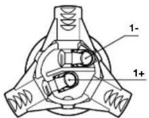
The CT SW10, 12 and 15 have a pair binding post connection terminals and one Neutrik Speakon connection socket on their rear panels. The binding post terminals provide quick and easy connection of stripped wires while Speakon sockets provide a more secure and reliable connection method.
If the binding post terminals are to be used, connect the positive cable to the red terminal and the negative cable to the black terminal. Incorrect connection can result in poor imaging and loss of bass. Figure 1 illustrates use of the binding post terminals.
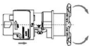
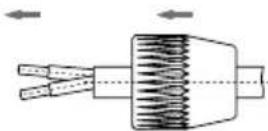
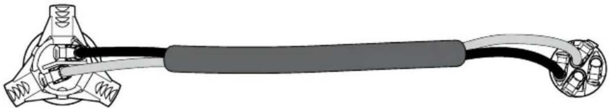
If the Speakon option is to be used, disassemble the Speakon plug as shown in Figure 2. Connect the positive cable to the terminal marked +1 and the negative cable to the terminal marked -1. Incorrect connection can result in poor imaging and loss of bass. Once the plug is reassembled it can be inserted into the socket and locked by twisting clockwise.
Ask your dealer for advice when selecting speaker cable. Keep its total impedance below the maximum recommended in the speaker specification and use a low inductance cable.
Connecting the Subwoofer Amplifier
All connections should be made with the equipment switched off.
The SA1000 amplifier has two pairs of binding post connection terminals and one four-pole Neutrik Speakon connection socket on its rear panel. The binding post terminals provide quick and easy connection of stripped wires while Speakon sockets provide a more secure and reliable connection method. Two identical subwoofer can be connected to the amplifier through use of either the two pairs of binding posts or the supplied four-pole Speakon plug.
If the binding post terminals are to be used, connect the positive cable or cables to the red terminals and the negative cable or cables to the black terminals. Incorrect connection can result in poor imaging and loss of bass. Figure 3 illustrates the use of the binding post terminals to connect one or two subwoofer.
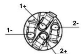
If the Speakon option is to be used, disassemble the Speakon plug as shown in Figure 2 connect the positive cable to the terminal marked +1 and the negative cable to the terminal marked -1. Terminals +2 and -2 are to be used when two subwoofoers are connected. Incorrect connection can result in poor imaging and loss of bass. Once the plug is reassembled it can be inserted into the socket and locked by twisting clockwise. Figure 4 illustrates the use of the Speakon plug to connect one or two subwoofoers.
Connect the signal input to the subwoofer amplifier using either the RCA phono or XLR options. A second subwoofer amplifier can be daisy-chained from the first by connecting to either the RCA phono or XLR output sockets.
Subwoofer Amplifier Setup and Control Before Auditioning
Before auditioning your new subwoofer installation and fine-tuning it, double check the connections. Make sure in particular that the phasing is correct. The positive terminals on the subwoofer (marked + and coloured red) should be connected to the positive output terminals on the amplifier and the negative terminals on the subwoofer (marked - and coloured black) connected to the negative output terminals on the amplifier. Incorrect connection can result a confused sound with poor bass.
Switching On and Off
The subwoofer amplifier is best switched on after any other item and switched off first. The On/Auto/Standby and Status Indicator operate as follows:
On: With the switch set to "On", the subwoofer amplifier will remain fully active and the indicator will glow green.
Auto: With the switch set to "Auto", the subwoofer amplifier will initially become fully active and the indicator will glow green. After about 5 minutes without an input signal, the subwoofer amplifier will automatically enter "sleep" mode. The indicator will glow red. When an input signal is detected, the subwoofer amplifier will automatically become active and the indicator will glow green. The subwoofer amplifier will return to sleep after about 5 minutes with no input signal.
Audio-visual processors incorporating an "automatic" set up procedure may be "confused" by a subwoofer amplifier with an auto switch-on/sleep function. A potentially damaging fault condition can arise. The subwoofer amplifier is best left switched on and fully active during set up if such a processor is used.
Standby: With the switch set to "Standby" the subwoofer amplifier will become active when it receives an appropriate trigger signal via its 12V Trigger Input. Turning off the 12V signal will return the subwoofer amplifier to sleep. The indicator will glow green when the subwoofer amplifier is active and red when the subwoofer amplifier is in sleep.
Setting The Subwoofer Amplifier Controls
There are 6 controls to consider:
The VOLUME (LINE) control.
The LOW-PASS FREQUENCY control.
The LOW-PASS FILTER switch.
The BASS Extension switch.
The EQUALISATION.
The PHASE switch.
The appropriate settings depend on the equipment used with the subwoofer and the modes of connection. If using more than one subwoofer amplifier, ensure the controls on each one are set the same.
Home Theatre Settings
Set the VOLUME control initially to the 9 o'clock position.
Set the LOW-PASS FILTER switch to OFF.
Set the BASS EXTENSION switch initially to position A.
Set the PHASE switch initially to 0^
Setting the LOW-PASS FREQ setting is irrelevant as the filter is switched OUT.
Set the EQUALISATION switch to MOVIE.
See the "Fine Tuning" section for more.
The subwoofer and subwoofer amplifier are not a THX^® licensed component, but may be used with a THX^® controller if desired. If a THX^® controller is used, ensure that the subwoofer function is enabled. This incorporates all the filtering and level setting required for the subwoofer in all modes. For level calibration, the internal test noise and channel level controls in the THX^® controller should be used. In all cases the levels should be set to obtain 75dB SPL (C-weighted) at the listening position from the controller's internal noise test signal.
With other processors, configure the front and surround speakers to "large" or "small" as appropriate before setting the levels. Use the internal noise test signal and volume controls of the processor to set the levels of all the speakers. Only change the VOLUME control on the subwoofer amplifier if there is not enough range in the processor to achieve the correct levels. Inexpensive sound level meters are readily available from electronics stores and can be used to calibrate the levels. Refer to your processor manual for further details on how to set the levels.
2-channel Audio Settings
Set the VOLUME control initially to the 9 o'clock position.
Set the LOW-PASS FILTER switch to ON.
Set the BASS EXTENSION switch initially to position A.
Set the PHASE switch initially to 180^
Set the EQUALISATION switch to MUSIC.
Set the LOW-PASS FREQ control to match the -6dB low frequency cut-off frequency of the satellite speakers. Note: Both -3dB and -6dB figures can be found in the specification of each B&W speaker model. If the satellite speaker manufacturer quotes only a - 3dB frequency, the optimum setting for the LOW-PASS FREQ control should be between 0.6 and 0.9 times that figure. The more gradual the low frequency roll-off of the satellite speakers, the lower the frequency should be set.
See the Fine Tuning section for more.
Fine Tuning
Before fine tuning, make sure that all the connections in the installation are correct and secure.
Home Theatre
In home theatre systems, the subwoofer (LFE) signal is a separate channel rather than an extension of the signal to the satellite speakers. The LOW-PASS
FILTER is switched off (or set to maximum), because the processor provides all the filtering for any speakers set to "small". However, the position of the PHASE switch must still be assessed. Normally the phase will be set to 0^ but if the subwoofer is positioned at a distance significantly different from the other speakers, or the power amplifier driving the other speakers happens to invert the signal, the 180^ position may be preferable. Listen with the switch in both positions and choose the one that gives the fullest sound. If there is little difference, leave the switch at 0^ .
Surround sound processors normally have a calibrated noise signal that can be used to set the relative levels of all the speakers, making the task somewhat more straightforward than for 2 channel audio. However, do not be afraid to alter the settings to your personal preference. It is all too easy to get carried away with the capabilities of the subwoofer, especially with some special low-frequency effects. Often a more realistic portrayal, and one more satisfying in the long term, is to be had by setting the subwoofer level lower than the standard calibration level.
2-channel Audio
Set the system up in the preferred position and play some programme with a steady bass content.
The optimum settings of the PHASE switch and the LOW-PASS FREQ control are inter-related and also dependent on the low-frequency cut-off characteristic of the satellite speakers. However, the settings recommended above for the LOW PASS FREQ control and PHASE switch have been chosen to integrate well with most satellite speaker bass alignments.
Using the initial settings, first check the setting of the PHASE switch. Choose the option that gives the fullest sound. Normally the recommended option will be optimum, but may not be in certain circumstances. These may be that the power amplifiers feeding the satellite speakers invert the signal or that the subwoofer is not placed close to the satellite speakers.
Next, adjust the VOLUME of the subwoofer amplifier relative to the satellite systems to your liking. Use a wide variety of programme material to get an average setting. A setting that sounds impressive on one piece may sound overpowering on another. Listen at a realistic volume level as the perception of musical balance varies with sound level.
Finally, adjust the LOW-PASS FREQ control to give the smoothest transition between the subwoofer and satellite speakers.
All Applications
The BASS EXTENSION switch offers three options of subwoofer bass extension. Position A gives the greatest extension and position C gives the least extension. Position B provides a compromise setting. If the system is to be used at very high volume levels or in a large listening room, restricting the bass extension by selecting either B or C may help ensure that the subwoofer is not asked to exceed its performance limits. In most situations the BASS EXTENSION switch should be left in position A.
The EQUILISATION switch alters the subwoofer bass roll-off alignment appropriate to MOVIE or MUSIC listening. The MOVIE position gives a "drier" alignment, more suited to the demands of action movie low frequency effects. The MUSIC position is suited to a faster more accurate bass line. The 3.5mm Equalisation input on the back panel is designed to receive a 12V signal that will toggle the MOVIE/MUSIC setting at the front panel. Set appropriately, the 12V trigger output of a processor can automate ideal performance of the subwoofer. If the front panel switch is set for MOVIE, the 12V trigger will change it to MUSIC. The reverse is also true. Care must be taken in setup of the processor in order to take advantage of this feature.
If you get problems with uneven bass - certain bass notes are exaggerated more than others - then you probably have a room interface problem and it is worth experimenting with the location of the subwoofer. What may seem like small changes in position - 15cm (6in) or so - can have a profound effect on the sound. The use of multiple subwoofoers can smooth the effects of room resonances, as each subwoofer will tend to excite resonances at different frequencies. If you appreciably alter the relative distances from the subwoofer(s) and satellite speakers to the listening position, re-assess the PHASE switch setting. You should also check the volume of the subwoofer (using either the processor output levels or the VOLUME control on the subwoofer amplifier as appropriate), but only after setting the phase correctly.
Running-in Period
The performance of the speaker will change subtly during the initial listening period. If the speaker has been stored in a cold environment, the damping compounds and suspension materials of the drive units will take some time to recover their correct mechanical properties. The drive unit suspensions will also loosen up during the first hours of use. The time taken for the speaker to achieve its intended performance will vary depending on previous storage conditions and how it is used. As a guide, allow up to a week for the temperature effects to stabilise and 15 hours of average use for the mechanical parts to attain their intended design characteristics.
However, longer run-in periods (as long as a month) have been reported and there is evidence to suggest that this has little to do with the speaker changing and more to do with the listener getting used to the new sound. This is especially so with highly revealing speakers such as these where there may be a significant increase in the amount of detail compared with what the listener has previously been used to; the sound may at first appear too "up front" and perhaps a little hard. After an extended period of time the sound will seem to mellow, but without losing clarity and detail.
Aftercare
The cabinet surfaces usually only require dusting. If you wish to use an aerosol or other cleaner, remove the grille first by gently pulling it away from the cabinet. Spray aerosols onto the cleaning cloth, not
directly onto the product. Test a small area first, as some cleaning products may damage some of the surfaces. Avoid products that are abrasive, or contain acid, alkali or anti-bacterial agents. Do not use cleaning agents on the drive units. The grille fabric may be cleaned with a normal clothes brush whilst the grille is detached from the cabinet.
Do not use the subwoofer as a table. When in use, objects left on top of the subwoofer are liable to rattle. In particular, avoid the risk of liquids being spilled (e.g. from drinks or vases of flowers).
If the system is taken out of use for a long period, disconnect the subwoofer amplifier from the mains supply.
Neutrik and the names of Neutrik products referenced herein are either trademarks and/or service marks of Neutrik.
Limited Warranty
This product has been designed and manufactured to the highest quality standards. However, if something does go wrong with this product, B&W Group Ltd. and its national distributors warrant free of charge labour (exclusion may apply) and replacement parts in any country served by an official B&W distributor.
This limited warranty is valid for a period of five years from the date of purchase or two years for electronics including amplified loudspeakers.
Terms and Conditions
1 The warranty is limited to the repair of the equipment. Neither transportation, nor any other costs, nor any risk for removal, transportation and installation of products is covered by this warranty.
2 This warranty is only valid for the original owner. It is not transferable.
3 This warranty will not be applicable in cases other than defects in materials and/or workmanship at the time of purchase and will not be applicable:
a. for damages caused by incorrect installation, connection or packing,
b. for damages caused by any use other than correct use described in the user manual, negligence, modifications, or use of parts that are not made or authorised by B&W,
c. for damages caused by faulty or unsuitable ancillary equipment,
d. for damages caused by accidents, lightning, water, fire heat, war, public disturbances or any other cause beyond the reasonable control of B&W and its appointed distributors,
e. for products whose serial number has been altered, deleted, removed or made illegible,
f. if repairs or modifications have been executed by an unauthorised person.
4 This guarantee complements any national/regional law obligations of dealers or national distributors and does not affect your statutory rights as a customer.
How to claim repairs under warranty
Should service be required, please follow the following procedure:
1 If the equipment is being used in the country of purchase, you should contact the B&W authorised dealer from whom the equipment was purchased.
2 If the equipment is being used outside the country of purchase, you should contact the B&W national distributor in the country of residence who will advise where the equipment can be serviced. You can call B&W in the UK or visit our web site to get the contact details of your local distributor.
To validate your warranty, you will need to produce the warranty booklet completed and stamped by your dealer on the date of purchase. Alternatively, you will need the original sales invoice or other proof of ownership and date of purchase.
EI control VOLUME (LINE).
EI control LOW-PASS FREQUENCY.
EI control EQUALISATION.
IPEDOCTEPEXEHNE:ДЯ CHNXEHN ONaCHOCTN BO3ropaHn Hn NopaxeHn 3NeKtpnuecknM TOKOM He NOdBepraTe DaHHbIn annapat BO3dEYCTBnIO DOxJn Hn Bnarn.
- Ecnn DnpeMOHTa Tpe6yIOCT 3anachbIe qactn, y6eINTEcB, YTO CNEuHaNtC cepBnCHoC nYk6bl NCNoNb3yeT ToNbKO 3aNCACTN, OROBOpEHhIE npOn3BOJNTeJIem Nn NmEIOUne TOHOr TaKHe XapaKTePncTNI, KAc OPnIHnHaJIbHbIe DeTaIIH. HeabTopn3OBAHHa 3aMeHa MoKeT npNVBeCTN K NoXkapy, yDapY TOKOM nn DpyrIM OnaCHOCTM.
- Поверъ, Heл по КOBрм Kaбел, KOТОрьг MOryT 6bIb NOВржднbl WUnamn KonoHok. He nepemeuaTe npOуКТ no nOly Ha WInax, T.K. OHN MOryT OTOpBaTbCrt OT Kopnyca N BbI3BaTb NOBpeKdEHHa. BydTe OCTOpoxHbI, YTO6bl He npOTKHBy Cebe HOrn 3TmN WUnamn.
21.ДЯнаджногаипг.TОнжарa nCNoB3yIte npedoxpaHHTeN TOJbKO yKa3aHHOrTo Tnna HOMHaHa.CTeBBie npedoxpaHHTeN
pa3MeueHbI KaK BHyTpN yCtPoNCTBa, TaK N Ha ero 3aAHei NaHei. 3aMeHa BHyTpEHHnx npdoxpanHTeien nopyuayTe Tolbko ABTopn3OBaHHomy nepcoHany. PpeOxApuHTei, KOToPbIE MOKeT 3aMeHrTb cam BnaJeNeu, yKa3aHbI CneUΦnKaun.
22.ДиИЗОЛЯЦИУСТЮСТВАОCTeTи HeO6xOДIMOBbIHyTb CeTeBOJ Ka6eJIb I3 pa3beMa Ha 3aДнeI NaHEn NIIb BbIHyTb BUNKy I3 CeTeBOJ pO3eTKN.II6o po3eTKa,IIN60 pa3bEm c3aДn DoJXeH OCTaBaTbCЯIerKO DoCTyNHbIM BO BpeMЯ pa6Otbl annapaTa.
23. 3TO yCTPOINCTBO DOJXHO NITaTbC TOnbKO HAnpRAKeHNEM, yKa3aHHbIM PdOM CO BBODOM cTeBOrO Ka6eJI. EcI IN Bbl He 3Haete, KaKo INCTouHnK 3NeKTPnueCTBa y Bac B DOME, INPOKOHcYNbTupyUteCb y DInepa nn INpeDCTaBNTeJI NOkAlbHO N3NeKTPocETN.
24. He neperpykaTe HacTeHHbIe po3eTKU, ydHnHTeJI NJI BCTpoEHhbIe po3eTKU, 3TO MOKeT npIBecrN K NOxApy, ydApY TOKOM NIN DpyrIM ONaCHOCTRm.
25. MarHHTHOe NOE - 3TO T npOdyKT co3daet
pacceHHoe MaHHTHOe NOE. He
peKOMeHNyETcA DePxKaTb
MaHHTOuyBCTBnTeNbHbIe NpeDMeTbI (HaNPmEp,
KNHeCKoNtBcRrT eNeBn3Opbl, DnCnIeN,
DnCKeTbI, MaHHTHbIe ayDIO N BnDeOKacCeTbI,
KapToUKn I T.I.) Ha pacCToAHnn MeHee O.5 M oT
ycTpOuCTBa. XndkokpncTaanlneckne (LCD) n
IIa3MeHHbIe 3KpaHbI He NoDbepKeHbI
BO3dEInCTBnIO MaHHTHbIX NOeN.
26. YctaHOBka - He CTaBBte 3TO yCTPOINCTBO Ha HeyCTOuHbYIO NOCTABKy, TpeHORY, CTOIKKY, KPOHHTeHN IIN CTOL. YCTPOINCTBO MOKeT UNaCTb H aHeCTN cepbe3HbIe paHENH NIN NOBpeXdEHNA. JIO6a YcTaHOBKa DOJXHa IpON3BOIDtbcr TOJIbKO B COOTBeTCTBmC INHCTpyKUHMN POn3BOIDTeJI.
He noDBepraIte n3dene B03dEeCTBnIO DOxJa, He nCNoB3yITe 3TO n3dEJIe B6N3n BObl, a TaKKe B yCNOBHX NOBbIeHHoB BlaXHOCTn, He CTaBbTe npEdMeTb, HAnOJIHeHhIe XnDKOCTbIO, HApPImep Ba3bl, Ha yCTpOcTB0, YTO6bl BHyTpB He IOnaJa XnIDKOCTb.
Pn yctaHOBKe ycTpoNCTBa y6eDntEcB,TO pO3eTKa, IIOo pa3bEm C3aIb BcerDa OCTaETcA NERKO IOCTyINHbIM BO Bpempa60tbl.
Ecnn Bo3HnKna HeuCnpaBHOCTb, HEmeJneHHO BbIKIOHTe CeTeBOE NITaHHe N BbIHbTe BUNKy yCTPOINCTBa n3 po3ETKn.
JaKe KOrda CeTeBOE NITaHHe OTKIOUeHO rIaBHBIM BbIKIOuHaTeJeM,3NeKTPnueCTBO npOJONXaET NOCTyNaTb B yCTpOInCTBO Ha MNHMmaJIbHOM yPOBHe. EcnBbl He cO6npaTeCb HcNoJIb3OBaTb 3TO yCTpOInCTBO B TeueHne IINTEJIbHOrO BpeMeHN, BbIHbTe CeTeByIO BUNKy U3 p03eTKN.
BVeDeHne
YBaKaembni nokynatelb,
Cnacn6o, YTO Bbl BbIbpaII N Bowers & Wilkins.
PonkaNyIcTa, IpOHTnte 3Ty INHCTpyKUIO BHIMaTeIbHO
peep pacnaKOBKO uYcTahOBKO npOdyKTa. 3To
nomoxET Bam ONTmIm3npOBaTb erO xapaKTePncTNIk.
B&W mMeet cetb cneuaHn3npoBaHHbIX
InCTpmbIOTopOB 60Jee, YEM B 60 CTpaHax, O OH
CMORYT NOMOy Bam pnp BO3HNKHOBeHn IIO6bIX
Ipo6JeM, C KOtOpbIMn He cnpaBUNc DnJIepbl.
HΦopMaunno 3aunTe Okpykaoue Cpebl

IpoDyKtBIB&WCo3aHbIBNoJHOM COOTBETCTBmCMeXdyHapOHyBMIM DnpeKTiBaMnNOOrpaHnueHnA M
NcNoIb3OBAHnO npChbIX MaTePnaIOB (Restriction of Hazardous Substances - RoHS) B 3JeKtpnueckom n 3JeKtpoHHOM o6OpydoBaHn, a TaKxe no er0 yTnI3aunn (Waste Electrical and Electronic Equipment - WEEE). 3NaK nepepeKHytoro MycopHoro 6aka 03Haaye T COOTBeTCTBVE dIpeKtNBam I TO, YTO pODoYKT DoJXeH 6bITb npabInbHO yTnIIN3OBaH nnn nepepa6OtaH.
IpoKoHcyNbTpyntecbBaWeimecTHoH opraHn3aunne, KOToPA 3aHmMaetcYTuIN3aunneOxOIOB, NO BOpocam npaBnBHOu CdaH BaUero O6OpydoBaHH B yTuNb.
B 3ToHnCTpyKuIN ONncbIaHOcra6ByΦepbl CT SW10,CT SW12 n CT SW15,aTaKxGe cOrnaCobAHbI C HmN,ABTOMaTH3nPOBaHHbI yCnInTeNb MoUHocTn SA1000, npedHa3NaueHHbI DnA MOHTaKa B CTOkY.
Copejxahne ynaKOBKn
PnoBepbTe coepKmOe ynaKOBKn ca6Bypepa HaHaHnUne:
1 dononHntelbHOn KOPO6Kn, coepkaaue:
4xM6 onophbx uINIOB
4xM6pe3nHOBbIXonopbl
4x KOHTprain (nloockne 10 MM)
1xDByxNIOChbI WTekep Neutrik Speakon
IpoBepbTe coepxHmoe Kopo6Kn C ycnntelem HaHaHnue:
1xceteboroKa6e
1 x uebipexnoniochoro uTekepa Neutrik Speakon
2xCKo6bI JnMAOTaKa B CToiKy
6X KOPOTKIN 6OJTOB C WecTnRpaHHbIMN rONOBKaMN Hsaib K Hm
4xpe3nHOBbix 3arJywek dIa OTBepctn
2xpyueK
4X DnHHbIX 6OJTOB C WecTnRpaHHbIMN rOJOBKaMn N
C6bBycpepbCT SW10, 12 n 15, a taKxe cDBoEHbI ycnnteB moHocTn dna Hx SA1000 co3daHbI dna HHctaannu IOMaunx TeaTPOB n dna ycIneneH 6acOB obyHbIX "noHOnuaNa3oHHbIX" KOHOK 2-KaHaNbHbIx aydno CnCTemax. JIObaa aydo n HcTaanra Tpebyet npOduMaHoro NOxDxa, UTObI packpbltBeCb NOTEHuaJI TexHKnI, n 3Ta IHCTpyKzIg NOMOXET BaM n HaPpaBNT B XODe BCero npocecca.
C6ByfehB ycnHtJeIb Tpe6yeT NOcEHNHeNn K 3neKtpnuecko CeT, N03Tomy BaXHO, YTO6bl Bbl O3HaKOMnJIncb C nHCTpyKUaMn No 6e3OanchoCTn n Co6IIOaIIBce YcNoBna. CoxpaHnte 3Ty INHCTpyKuio B HaJeXHom MeTe dJa o6paueHnB 6yduem.
YcTaHOBka n pa3MeueHne ca6ByΦepa
C6bpyepBcpeHCT SW npedHa3NaeHbI nnyctaHOBNIO B cyueCTByuOyU, NIOB 3aka3HyIO Me6enb IJa DomaawHero TeaTpa, npn 3TOM nn6nn3KO K ypOBHIO NOA, Hn Ha Noy.
Ecni ca6ByepeoJxHc6bItyCTaHOBJIeH B Me6eNi, BaxHo y6eIITbcra, YTO 3Ta Me6eJIb MOKeT BblEpxaTb Bec ca6Byepepa n YTO ee KOHCTpyKuHa IocTaToUHO npOuaHa. CyueCTBeHHbte Bn6paunn NaHeJe Me6eNi MOrYt Cepbe3HO NOBNIHTb Ha cy6BeKtNBHO BOCpNrtne KauecTBa 3ByuHaHn ayDnO cnCTembl. BBNHnBaIOUneCer pe3INHOBbie ONopbl N3 KOMPNeKTa NoCTaBKn PnIKpePnIAOTcR K HnXHeN NOBepxHOCTu Ca6Byepepa YTO6bl 3aUNITb OTDeNKy Kopnyca n NOdaBNTb Bn6paunn.
Ecn ca6ByepdoJxHc6bIb yCTaHOBHeh CBO6OHO Ha noJy, BaxHo o6ecneuHTb erO ycToHHBOe noloxHenC nmoUbO ONOpHbIX WnOB, BcOy, rTe 3TO BO3MOXHO. Wnbl paCCHTaHbHa To, YTObI npOTKHyTB KOBe H OINpaTbcra Ha NOBExHOCTb NoA.ChaYana HABEPHNTe KOHTprAaKn Ha Wnbl TaK, YTObIOCTaNC He6oBbWon 3a3Op Ha d KOBpOM pN WnPAX, PPOHc CTOruix Ha noy. 3aTeM 3aBepHtE Wnbl Do ynpa B OTBepCTnC pe3b60B B OCHOBAHN KOPnyCa.Ecnn KOpNy Swataetc, OTBepHtE Ha3aD Napy WnOB, KOTOpbIe He KaCAIoTcNoJa, YTObI OH npOHO BCTaHa BCE ONOpbl.
HaKoHeu, 3aTaNHTe KOHTprAynB CTOPOHy KOpnyCa nn nnnTbI. Boone ydo6Ho OTperylnpoBaTb BbICOTy WnOB Nocne TORO, KaK Bbl Bbl6epTe ONTMaJIbHOe MecTo dna ca6ByΦepOB.
Haun yun nnox OyBCTbyOT HanpaBneHne Ha
NCTOCHNK Hn3Knx 3ByKObblx YaCTOT, TaK YTO
pa3meueHne ca6ByΦepOB B KOMHaTe
npocnyuBaHnO oblyHo MeHee KpntuHO, Yem DnA
NoHOnDaNa3oHHbIX KOLOHOK. Tem He MeHee,
ROBOPrT, YTO HanLyUwne pe3yIbTaTbI O6blHO
IOCTuraOTcR, ecn Ca6ByΦep pacNoJoxKeMexDy
PpABoN I neBOJ φpoHTaJIbHbIMN KOLOHKAMN, INN
No6bn3OCTn OT OndHn I3 HNX. EcIn NcNoJIb3yOTcR
DBa Ca6ByΦepa, LyuWe BCero OdIN NOCTaBNTb
PraDM C neBOJ KOLOHKO, a dpyro - c npabOi.
Pa3MeHHe ca6Byepe 3a KpcnOM cnywateJ, DaKe B MHOrOkaHaIbHOIN CNTEme OKpyXaIOUeRO 3ByKa, O6bHuO pInBOIDNT K yxyDWeHIO 3BYKOBORO 6pa3a, HO MoKET OKa3aTbcra NpneMnEMbIM KOMnpOMnCCOM Ha clyuA, ecnn YcNOBnB D Ome He I03BOJIOT INHOE.
Tak je, kaN iJn Bcex dpyrnx KOJIOHOK, 6JIN3OCTb rpaHnKOMHaTbI CnJIbHO BInReT Ha 3ByuHHe ca6Bypepa.ΓpOMKOCTb 6aca Bo3pacTaet no Mepe TORO, KaK CTeHbI CTAHOBATc8bnKe K cABypepy. Odnako, BOITnUne OT NOHOnaNa3OHbIX KOJIOHOK, 06nn ToHaJIbHbI 6aHaHC CNCTEmbl MoXHO
noKoppeKtnpoBaTc nOMOuBIO peryJATopa
rpomKocTn ca6Byepa. Yem 6oNbwe 3ΦpeKT OT
rpaHn KOMHaTb, TeM MeHbWe DOJXHa 6blTb
BbCTabIeHa rpmKocTb, N TEM IerYe Ca6Bypepy
pa6oTa; Ondako TyT eCTb N O6OpOTHa CTOpOHa.
Ca6BypebI, pa3MeueHHbIe 6JI3KO K yIJaM, qACTO
reHepnpyOT 60lbWe HN3KOaCTOTbIX pe3OHaHCOB B
KOMHATE, DeNaB 6ac Ee 6OJe HepaBHomepHbIM NO
yactote. B TAKo cnTyauun HnTu He CMOxET
3aMeHnTB 3KcnepUmEHT, T.K. BCE KOMHaTb BEyT
ce6nNo-pa3HOMy, CNeIOBaTeNbHO Ca6Bypep HyXHO
NONpOboBaTb yCTaHOBtB CBmIx pa3HbIX MecTx
npExdYe NpInHbOkOHaTeNbHOe PeSeHne.
Kaok-N6byMb My3bIKaJIbHbIy OTPbIBOK C 6acoBOH
HToI, NoDbimaUeNCn IIN OnyCKaUeNCn NO
My3bIKaJIbHOuKaIe, MOKeT OKa3aTbCn NOJe3HBIM
PnOueHke rnaDkoCTn 6acoBOrO OTKnIka.
IpocNywaIte 3OT φpaMeHT KaK Ha 6oJbwoi, TaK
Ha MaOn rpmKocTn.
IcnoJIb3OBAHHe MHornx ca6BypepoB B OdHO IHCTaJIaUcIMMOKeT yIyUuNTb KaueCTBO 3ByuHaHn HECKoJIbKIMN CnocO6aMn:
-Подержаь pa3делене ctepeо kaHaNoB Ha cambIX Hn3Knx YacToTAX.
CrtnaNTbBJIaHHe Hn3KoYacTOTHbIX pe3OHaHCOB NOMEueHn.
- 103BOJNT IOBbICHTb MaKcIMaJIbHOe 3ByKOBOE DaBJIeHne.
EcnI DbCa6ByΦepa NcNoB3yOTcB 2-KaHaIbHO ayDnO CnCTeMe, CTpeo pa3DeJeHne 6yDet yNyUWeHO TOJbKO B TOM Cnyae, KOrDa KaKDbI KaHaI NMeET CBOI CO6CTBeHHbI Ca6ByΦep, pa3MeueHHbI NO6JIIN3OCTN OT COOTBeTCTByIOSei CaTeJIInTHOH KOJOnHKN.
PaccenHHoe MaHTHOJ noJe
HnHAMKn ca6ByepeOB co3daIOT mARHTHOE NOJe, BbIXOJaee 3a npedeJIb Ix KOpnycoB. Mbl peKOMeHNyEm DepxKaTb MaHHTOUYBCTBNTeJIbHbIE npedMeTbI (KNHeCKoNHBie TeJIeBN3Opbl, INCnJIeN, INCKeTbI, MaHHTHbIe ayDIO N BuDeOKacCeTbI, KapTOUKN T.I.) Ha paCCTOARHH MNHMMy0.5 M OT KOJHOK. XndKokpuctanIIueckne (LCD) n Pna3MeHHbIe 3KpaHbI He NoDBepXeHbI BO3DeIcTBIO MaHHTHbIX NOJIe.
3aunTHbIe peWetKn
Ca6ByΦepb Cepn CT SW obopydoBaHb 3aunTHbIMPeueTKamc MaHHTbIMn KpePHeHnAMn, n ux JERKOMOxHO CHrTb, ecnn Bbl 3axOTnTe. IocTapaNTecb HeNOBpeINTb DnΦpy3Opbl DnHaMKOB pnp CHrTNn NIm3aMeHe rpnne (3aunTHbIX peWeTOk).
YctahOBka ca6ByΦepHoro yCnIteJIa
Ca6ByeepHbI yCnInTeJIb SA1000 npedHa3NaueH IIN HCTaJIaIcII B CTAHdApTHyIO 19-IOIMOBYIO cToIKy dIa O6OpyIOBaHNI. OH nOCTaBnIeTcA C "UwAMN" DnM MOtJka, ODAKO 6oITbI N rAIKN dJI KpeIeHNI B KOMNKeKT He BXOJaT. Y6eIITecB, IocNe yCTaHOBKn B CTOIKy, YTO oEcecneH JERKNI DOCTyn BO3dyXa KycuINTeJIIO, N YTO eRO BEHTNJAUONHHbIE OTBepCTNIHnHEm He 3aKpbITbl.
MOHTaX SA1000 B cToiKy
SA1000 noCTaBnEETCA BmecTe C DByMa CKo6aMn Iy yCTaHOBKn B cTaHapTHyIO CTOnKy. Iy TOrO YTo6bl npNKpeNITb CkO6bl:
PnncTaBbTe c60ky cKo6y n BcTaBbTe TpN KOpOTkNx 60NTa C WeCTnIgpaHHbIMN IOnOBKaMn TaK, YTO6bl OHN BOJIN B OTBepCTnHa 60KOBbIX NaHeJAX ycunnteJI.
Iobtopnte To JKe caMOe dNn cKo6blc npyro CTOpOHI yCUNNTeJI.
Puykn dna SA1000
Cko6blIyCTaHOBKn BCTaHdApTHyIO CTOnKy NOCTaBnHTcBMeCTe CpyKamN, KOTOpbIe MOxHO NOCTaBnTb IIN CHrTb. 3TN pyKu KpeIATc R NOMOu Hapbl DnHHbIX 6oJIToB C WeCTurpaHHbIMN TOnOBkAMN, KOTOpbIe npoxOJr Ype3 Hx Npe3 CKO6bl.Ecnn Bb He nCNoJIb3yeTe pyKu, 3akpoITe OTBepCTnI dIy Hx pe3HNOHBIMN 3arLyWKAMN.
YcTaHOBka BHyTpEnHnX nepembIueK EQ b ca6ByΦepHom ycHInTeNe
Ca6ByΦepHbI yCnIITeB SA1000 06OpyIOBaH nepeMbIcMn IaI aONHInTeBHO TOnKo HAcTpoKn erO 3KbAan3epa nXapaKTePncTkn PoKIOueHHoro K hemy CT ca6ByΦepa. Do 3TxN nepeMbIeK MoXHO dO6paTbcR, ToJbKO ydaJIuB Ta6NIuKy, (CM. pnc.5) nNo3ToMy TaKaar Oepaunr DOJxHa npOBODTbcR KBaUNΦnUPOBaHHbIM cepBnCHbIM NEpCOHaIOM.
PoeHHeHcabByyepHOrO yntTeIa
Ca6BycpehBn ycnnteB SA1000 o6OpydoBaH pa3HoO6pa3HbIMrHe3dAmn npa3bEmamn Ha 3aDne nAHeN:
1 x pa3bem dnn CeTeBOro Ka6eJn: IOncoeDnHnteero K ceTeBOI po3eTKe C NOMOsbIO NOxOJaero dna Bawero pernoHa Ka6eJn.
1x Neutrik Speakon BbIXoHNo pa3bEm: YeTbIpeXnOIOChbI pa3bEm Speakon n03BOJnEcoeHNHTb OIN Hn IN Da (NDeHTnUHbIX) ca6Bypepa. THe3da Speakon oBeceNeuBAIoT 6Onee 6e3OnaCHOe HnAdExHoe CoeINHeHne, Yem 3aUnSeHHbI pOBoD INn 4MM rHe3do.
4X KOLOHOUHbIX KJIeMMbl: DBe napbl KOLOHOUHbIX KJIeMM oBecneuBaIOT aIbTePHaTnBHOe NOKIIIOueHHe 3aUHcEHbIM PPOBOOM IIN YpeE3 4-MM rHe3do dJr ODHOro INN DBYx (IeHTnHHbx) ca6ByΦepOB.
1xRCA Phono BxoJb:BXoHNo pa3bem dno coeDnHeHH c a6ByΦepHbIM bblXoDM AVnpoueccopnnnpeducnnten.
1xXLR BXoJ: aIbTePHaTUBHbI BXoHOH 6aIaHChbI pa3bEm IJIa COeINHeHN C ca6BypepHbIM BbIXODom AV-npoceccopa nnn npeducnntela.
1xRCA Phono BbIXoI: BbIXoHoi pa3bEm Ia coeDInHeHH C BXoOM BTOPOrO ca6ByΦepHO r yCUNITeJI.
1xXLR Bixo: aIbTepeHaTnBbIy BIXOHOJ 6aIahChbI pa3bEm IJIa COeINHeHc CBXODOM BTOPOc6ByepHoro yCUNNTeJIa.
2x3.5MM MmHn-IXeK - TprrrepHbIe BXOdbI: 12-B TprrrepHbIe BXOdbI dIa aBTOMaTH3nPoBaHHoro ynpabLeHn nepexoDm ycJInteJI B peXIM standby, a TaKxe nepeKnIOUeHn IpeDyCTaHOBOK movie/music.
MeToDbI CoeHHeHn Ca6ByΦepHOrO yCnHtTeJc Ca6ByΦepom, BKIOUaH NcNoB3OBaHne pa3bEmOB Speakon,OnncbIbAeTcB pa3dene IOpDCoeHHeHne (Connecting) Hxke.
OpraHbI ynpaBHeHnBa6ByΦePbIM ycNITeJIeM
Ha nepedne nane nn cabbyepnoro ycnnten SA1000 haoantc nedeyioune oprahtynpaBHeHH.
Volume - FrpomKocTb: perynpyet obuIyI rpmKocTb ca6Byepa.
Filter - Φι NBtp: YcTaHaBnBaET HxKHOU yAcTOTy cpe3a φι NBtpa ca6Bypepa.
Low-pass In/Out - OTKIIOUeHne 0nJIbTpap: BKNIOUaET nIN OTKIIOuaeT 0nJIbTp ca6Bypepa.
1x4-pole Neutrik Speakon
2x默马云德
6x三元异()
4x古水
2×
4×△三异(),
SA1000 串串串串串串串串串串串串串串串串串串串串串串串串串串串串串串串串串串串串串串串串串串串串串串串串串串串串串串串串串串串串串串串串串串串串串串串串串串串串串串串串串串串串串串串串串串串串串串串串串串串串
SA1000备
SA1000 串串串串串的串串串串串串串串串串串串串串串串串串串串串串串串串串串串串串串串串串串串串串串串串串串串串串串串串串串串串串串串串串串串串串串串串串串串串串串串串串串串串串串串串串串串串串串串串串串串串串串串串串串串
Volume: 1
Filter: Lwu Tst OoP uPn Suu nOe
Low-pass In/Out: 串串串串串串串串串串串串串串串串串串串串串串串串串串串串串串串串串串串串串串串串串串串串串串串串串串串串串串串串串串串串串串串串串串串串串串串串串串串串串串串串串串串串串串串串串串串串串串串串串串串串
Phase: トトドフ 香默興龍
STANDARDS CONFORMITY
NORTH AMERICA

Conforms to ANSI/UL Standard 60065 7th Edition
Certified to CAN/CSA Standard C22.2 No. 60065

Complies with Part 15 of the FCC Rules
Operation is subject to the following conditions:
- This device does not cause harmful interference and
- This device must accept any interference received, including interference that may cause undesired operation.
EU DECLARATION OF CONFORMITY
We,
B&W Group Ltd.
whose registered office is situated at
Dale Road, Worthing, West Sussex, BN11 2BH, United Kingdom
declare under our sole responsibility that the products:
SA1000
comply with the EU Electro-Magnetic Compatibility (EMC) Directive 89/336/EEC, in pursuance of which the following standards have been applied:
EN55020:2002
Sound and television broadcast receivers and associated equipment - Immunity characteristics
EN55013:2001
Sound and television broadcast receivers and associated equipment - Radio disturbance characteristics
EN61000-3-2:2000
Electro-magnetic compatibility (EMC) — Part 3-2: Limits - Limits for harmonic current emissions (equipment input current up to and including 16A per phase)
EN61000-3-3:1995
Electro-magnetic compatibility (EMC) - Part 3-3: Limits - Limitation of voltage changes, voltage fluctuations and flicker in public low-voltage supply systems, for equipment with rated current ≤ 16 per phase and not subject to conditional connection
and comply with the EU Low Voltage Directive 73/23/EEC and amendment 93/68/EEC, in pursuance of which the following standard has been applied:
EN 60065:2002
Audio, video and similar electronic apparatus - Safety requirements
This declaration attests that the manufacturing process quality control and product documentation accord with the need to assure continued compliance.
The attention of the user is drawn to any special measures regarding the use of this equipment that may be detailed in the owner's manual.
Signed:

G Edwards
Executive Vice President, Operations
B&W Group Ltd.
EU DECLARATION OF CONFORMITY
We,
B&W Group Ltd.
whose registered office is situated at
Dale Road, Worthing, West Sussex, BN11 2BH, United Kingdom
declare under our sole responsibility that the products:
CT SW10, CT SW12, CT SW15
comply with the EU Electro-Magnetic Compatibility (EMC) Directive 89/336/EEC, in pursuance of which the following standards have been applied:
EN61000-6-1:2001
EN61000-6-3:2001
EN55020:2002
EN55013:2001
and comply with the EU General Product Safety 2001/95/EC, in pursuance of which the following standard has been applied:
EN60065:2002
This declaration attests that the manufacturing process quality control and product documentation accord with the need to assure continued compliance.
The attention of the user is drawn to any special measures regarding the use of this equipment that may be detailed in the owner's manual.
Signed:

G Edwards
Executive Vice President, Operations
B&W Group Ltd.

SA1000
Description Dedicated 1000W amplifier for the CT SW Series
Functions Front panel controls: rotary volume (line in) Rotary low-pass filter frequency (4th-order Linkwitz, 40Hz -140Hz) Low-pass filter defeat 2-position switch Phase 0/180 2-position switch Bass extension 3-position switch Movie/music EQ 2-position switch On/auto/standby 3-position switch Status LED Fault LED
Inputs Line In (XLR & RCA Phono) 1x RCA photo socket, line in 1x RCA phono socket, link out 1x XLR socket, line in 1x XLR socket, link out 3.5mm jack - 12V trigger on/standby (overrides manual standby setting) 3.5mm jack - 12V trigger equalisation movie/music
Outputs 1x Speakon 4-pole speaker socket 2x pair of binding posts
Rated power consumption 300W 34W - ldling 3W - Standby
Dimensions Height: 100mm (3.9 in) (88.5mm (3.5 in) without feet) Width: 430mm (16.9 in) Depth: 322mm (12.7 in) Front panel height: 2U 88.1mm (3.5 in)
Net weight 6.45kg (14.3 lb)
CT SW10
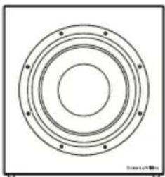
Technical features Paper/Kevlar cone bass driver
Description Closed-box subwoofer system with rack-mount amplifier
Drive unit 250mm (10 in) paper/Kevlar cone long-throw
Frequency range -6dB at 18Hz and 25/140Hz adjustable (EQ at A)
Frequency response (±3dB) 26Hz-40/140Hz adjustable (EQ at A)
Bass extension -6dB at 18Hz (position A)
-6dB at 23Hz (position B)
-6dB at 29Hz (position C)
Weight 14.85kg (32.7 lb)
Dimensions H 360mm (14.2 in)
W 340mm (13.4 in)
D 260mm (10.3 in)
Depth with grille: 290mm (11.4 in)
CT SW12
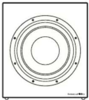
Technical features Paper/Kevlar cone bass driver
Description Closed-box subwoofer system with rack-mount amplifier
Drive unit 300mm (12 in) paper/Kevlar cone long-throw
Frequency range -6dB at 17Hz and 25/140Hz adjustable (EQ at A)
Frequency response (±3dB) 24Hz - 40/140Hz adjustable (EQ at A)
Bass extension -6dB at 17Hz (position A)
-6dB at 22Hz (position B)
-6dB at 26Hz (position C)
Weight 25kg (55.1 lb)
Dimensions H 465mm (18.3 in)
W 396mm (15.6 in)
D 260mm (10.3 in)
Depth with grille: 290mm (11.4 in)
CT SW15
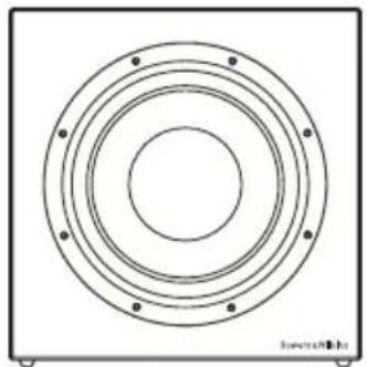
Description Closed-box subwoofer system with external rack-mount amplifier
Drive unit 380mm (15 in) paper/Kevlar cone long-throw
Frequency range -6dB at 16Hz and 25/140Hz adjustable (EQ at A)
Frequency response (±3dB) 20Hz - 40/140Hz adjustable (EQ at A)
Bass extension -6dB at 16Hz (position A)
-6dB at 20Hz (position B)
-6dB at 25Hz (position C)
Power handing 1000W
Weight 30kg (66.1 lb)
Dimensions H 550mm (21.7 in)
W 550mm (21.7 in)
D 260mm (10.3 in)
Depth with grille: 290mm (11.4 in)
Finish Cabinet Black painted
Grille Black cloth
Bowers & Wilkins
B&W Group Ltd.
Dale Road
Worthing West Sussex
BN11 2BH England
T +44 (0) 1903 221 800
F+44(0)1903221801
info@bwgroup.com
www.bowers-wilkins.com
B&W Group (UK Sales)
T+441903221500
Euksales@bwgroup.com
B&W Group North America
T+19786642870
E marketing@bwgroupusa.com
B&W Group Asia Ltd.
T +852 2 869 9916
E info@bwgroup.hk
Neutrik and Speakon are registered
trademarks of Neutrik AG.
Kevlar is a registered trademark of DuPont.
Copyright © B&W Group Ltd. E&OE
Printed in China.


- Contents
- English
- Français
- English Installation and Setup Manual
- Important Safety Instructions
- WARNING: To reduce the risk of fire or electric shock, do not expose this apparatus to rain or moisture.
- Introduction
- Environmental Information
- Carton Contents
- Subwoofer Installation and Positioning
- Stray Magnetic Fields
- Grilles
- Subwoofer Amplifier Installation
- Rack Mounting the SA1000
- SA1000 Rack Handles
- Subwoofer Amplifier Internal EQ Jumper Settings
- Subwoofer Amplifier Connections
- Subwoofer Amplifier Controls
- Connecting the Subwoofer
- Connecting the Subwoofer Amplifier
- Subwoofer Amplifier Setup and Control Before Auditioning
- Switching On and Off
- Setting The Subwoofer Amplifier Controls
- Home Theatre Settings
- 2-channel Audio Settings
- Fine Tuning
- Home Theatre
- 2-channel Audio
- All Applications
- Running-in Period
- Aftercare
- Limited Warranty
- Terms and Conditions
- How to claim repairs under warranty
- IPEDOCTEPEXEHNE:ДЯ CHNXEHN ONaCHOCTN BO3ropaHn Hn NopaxeHn 3NeKtpnuecknM TOKOM He NOdBepraTe DaHHbIn annapat BO3dEYCTBnIO DOxJn Hn Bnarn.
- BVeDeHne
- HΦopMaunno 3aunTe Okpykaoue Cpebl
- Copejxahne ynaKOBKn
- YcTaHOBka n pa3MeueHne ca6ByΦepa
- PaccenHHoe MaHTHOJ noJe
- 3aunTHbIe peWetKn
- YctahOBka ca6ByΦepHoro yCnIteJIa
- MOHTaX SA1000 B cToiKy
- Puykn dna SA1000
- YcTaHOBka BHyTpEnHnX nepembIueK EQ b ca6ByΦepHom ycHInTeNe
- PoeHHeHcabByyepHOrO yntTeIa
- OpraHbI ynpaBHeHnBa6ByΦePbIM ycNITeJIeM
- SA1000备
- STANDARDS CONFORMITY
- NORTH AMERICA
- EU DECLARATION OF CONFORMITY
- SA1000
- CT SW10
- CT SW12
- CT SW15
- Bowers & Wilkins
Brand : BOWERS & WILKINS
Model : CT SW10
Category : Subwoofer