
ISW3 - Subwoofer BOWERS & WILKINS - Free user manual and instructions
Find the device manual for free ISW3 BOWERS & WILKINS in PDF.
| Product Type | In-wall Subwoofer |
| Brand | Bowers & Wilkins |
| Model | ISW3 |
| Applications | Ceiling, wall, floor, closet or kitchen cabinet |
| Included Accessories | Front grille, canopy, hood extension, cutout template, damping trim strips, corner brackets, support bar, rubber feet with lock nuts, various screws |
| Required spacing between joists | Minimum 40 cm (16 inches) |
| Required rear clearance | At least 25 cm (10 inches) |
| Wiring | Speaker cable, connection via spring terminals with polarity observance |
| Grille painting | Possible with most wall paints |
| Maintenance | Regularly remove and clean the grille; vacuum the underfloor cavity if installed |
| Break-in | Approximately one week for temperature, 15 hours of use for mechanical |
| Safety | Solid fixing of brackets to avoid vibrations; use of damping trim |
Frequently Asked Questions - ISW3 BOWERS & WILKINS
User questions about ISW3 BOWERS & WILKINS
0 question about this device. Answer the ones you know or ask your own.
Ask a new question about this device
Download the instructions for your Subwoofer in PDF format for free! Find your manual ISW3 - BOWERS & WILKINS and take your electronic device back in hand. On this page are published all the documents necessary for the use of your device. ISW3 by BOWERS & WILKINS.
USER MANUAL ISW3 BOWERS & WILKINS
Welcome to Bowers & Wilkins and ISW-3
Thank you for choosing Bowers & Wilkins. When John Bowers first established our company he did so in the belief that imaginative design, innovative engineering and advanced technology were keys that could unlock the enjoyment of audio in the home. His belief is one that we continue to share and it inspires every product we design.
www.bowers-wilkins.com
1 Contents
Check that you have the following components shown in Figure 1:
a.Subwoofer
b. Louvre fascia (white)
c. Louvre (black)
d. Cowl extension
e. Cut-out template
f. Gasket strips
q. Angle support brackets
n. No.8 x 12mm (0.5in) screws
i. M3 x 35mm (1.38in) button head screws
i. Support bar
k. Rubber feet & locknuts
1. No.4 x 10mm (0.38in) csk screws
m.No.6 x 25mm (1in) csk screws
In addition, you should also have a Quick Start Guide and warranty leaflet. This manual provides more detail than the Quick Start Guide.
Consult your dealer if any parts are missing or appear damaged.
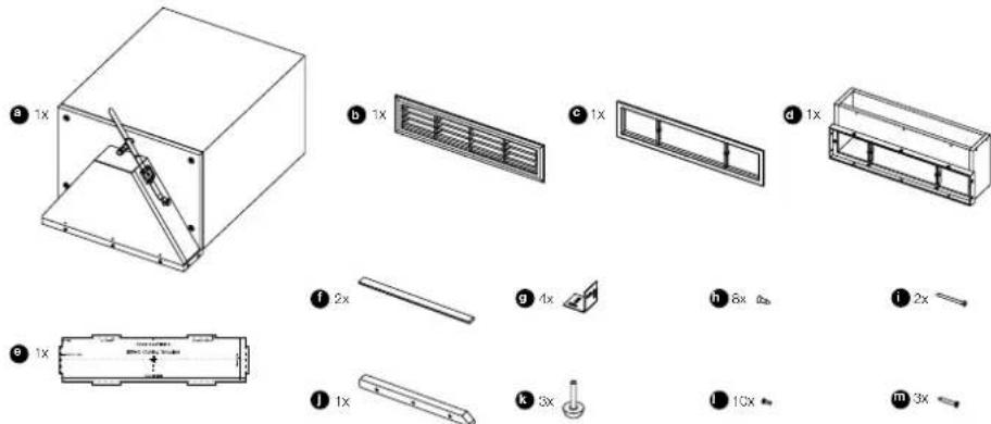
Figure 1
2 Applications
There are four possible applications, each covered by a separate section:
In-ceiling - new construction only (Figure 2)
Go to Section 3.
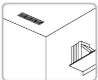
Figure 2
In-wall - new construction only (Figure 3)
Go to Section 4.

Figure 3
Under the floor (Figure 4) Go to Section 5.
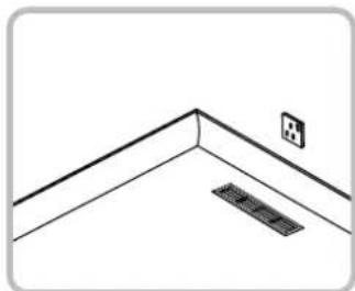
Figure 4
In a kitchen unit (Figure 5) Go to Section 6.
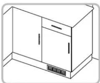
Figure 5
3 Installation in-ceiling
The speaker will fit between joists with standard 40cm (16in) or greater spacing, such that the visible louvre straddles the gap between them. A clearance of 25cm (10in) or greater behind the underside face of the joists is required.
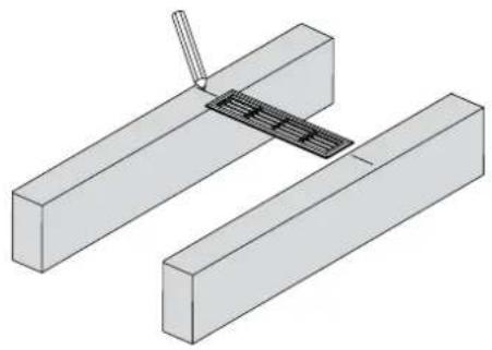
Mark the centre line of the desired louvre position on the underside face of the joists at each side. Make two further marks on both joists at approximately 75mm (3in) and 380mm (15in) from the louvre centre line for the cabinet support brackets (Figure 6).
Screw the four L-brackets (g) as shown to the inside vertical faces of the joists (screws not supplied), ensuring the brackets are square and flush with the underside face of the joists.
Run appropriate gauge speaker cable to the installation point. Secure it to the joists so it cannot rattle, with the final tie point close to the marked louvre centre line near the top of the joist. Leave approximately 30cm - 50cm (12in - 20in) free at the end (Figure 7).
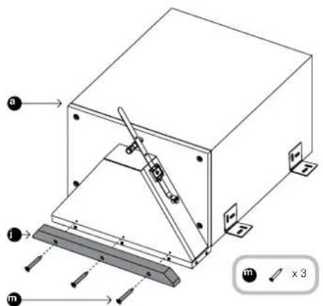
Attach the support bar (j) to the cowl using the three No.6 x 25mm screws (m) and pre-drilled holes (Figure 8).
Remove the backing paper and apply the two self-adhesive gasket strips (f), one to the support bar and one to the cabinet at the other side of the louvre frame. These will bear on the drywall panel to avoid rattles (Figure 9).
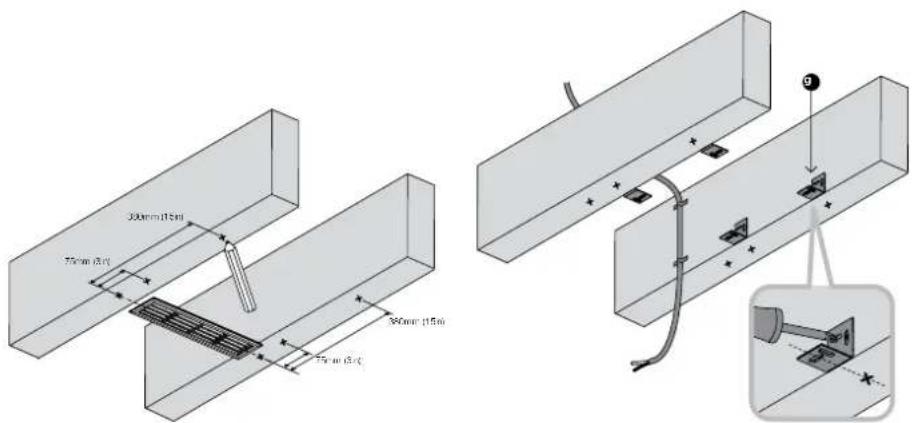
Figure 6 Figure 7
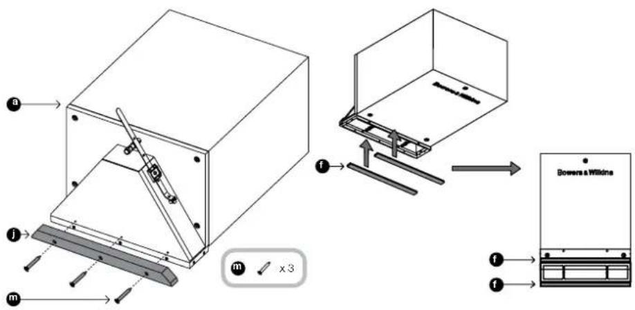
Figure 8
Figure 9
Lift the speaker to rest as shown on the four L-brackets. If the joist spacing is too great to allow screwing through the brackets into the cabinet, a custom support method will need to be applied by the installer.
Line the centre of the louvre aperture with the marks on the joists and square it up relative to the walls.
Fix the cabinet position, using the No.8 x 12mm self-tapping screws (h) through the L-brackets into the cabinet (Figure 10).
The louvre frame will protrude below the bottom face of the joists.
Strip the ends of the cable and connect to the spring terminals on the cabinet, observing correct polarity.
To prevent rattles, secure the excess cable using the cable tie attached to the subwoofer (Figure 11).
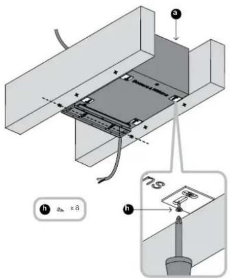
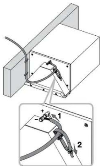
Figure 10 Figure 11
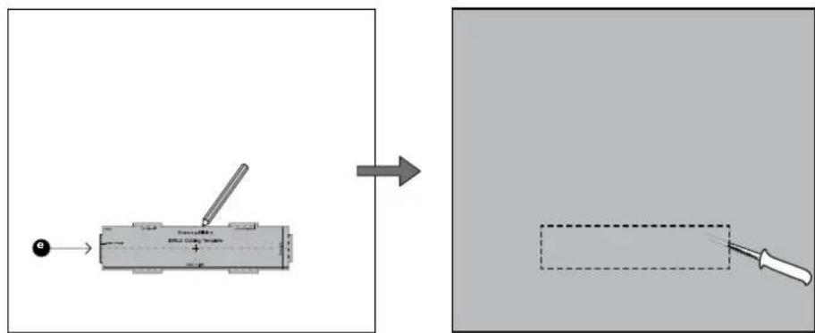
Use the cut-out template (e) to mark the aperture on the drywall panel. The six protrusions correspond to the outer dimensions of the louvre fascia and are provided to indicate necessary clearance. Do not mark round these protrusions, but rather along the dotted lines that cross them (Figure 12).

Figure 12
At this point, you may apply flexible mastic to the face of the subwoofer cabinet to prevent rattles against the ceiling panel.
Fit the frywall panels to the ceiling joists (Figure 13) and apply the final skim coat.
Paint the ceiling at this stage and, if desired, paint the louvre fascia moulding (b) to match. The part will take all normal wall paints.
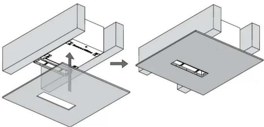
Figure 13
Attach the louvre (c) to the front of the opening and secure it to the louvre frame using the two M3 machine screws (i) through the two bars. Do not over-tighten. There should be slight bending tension in the two louvre bars, but the surround should not be distorted or the fascia will not fit correctly.
Clip the fascia (b) to the louvre (c) (Figure 14).
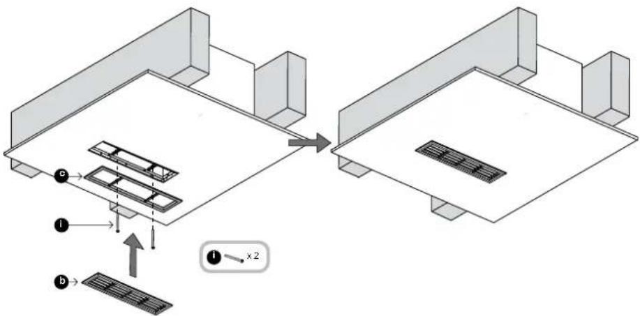
Figure 14
4 Installation in-wall
The subwoofer is too deep to fit into a standard nominal 100mm (4in) thick wall, but may be fitted into custom furniture or closet that accommodates its depth and that has studs with standard 40cm (16in) or greater spacing.
In most situations, the visible louvre will be required to be low on the wall, just above the skirting board. In that case, the cabinet will be oriented with the cowl at the bottom.
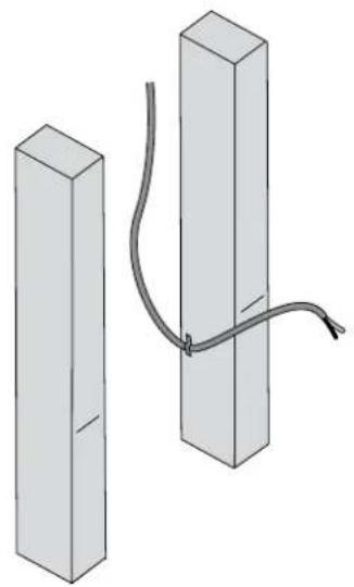
On the front face of the studs each side of the subwoofer, draw a horizontal line marking where the centre line of the louvre fascia should be (Figure 15).
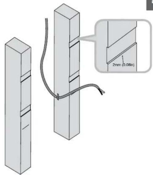
Run appropriate gauge speaker cable to the installation point. Secure it to the studs so it cannot rattle, with the final tie point close to the marked louvre centre line. Leave approximately 30cm - 50cm (12in - 20in) free at the end (Figure 16).
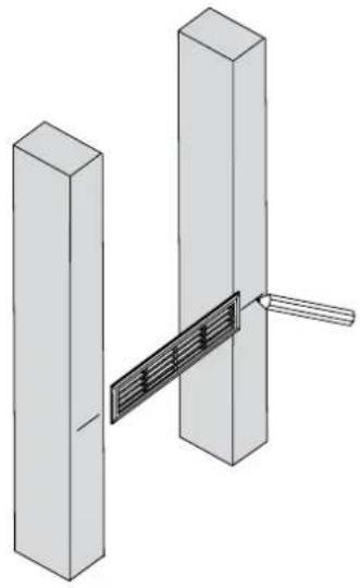
Figure 15

Figure 16
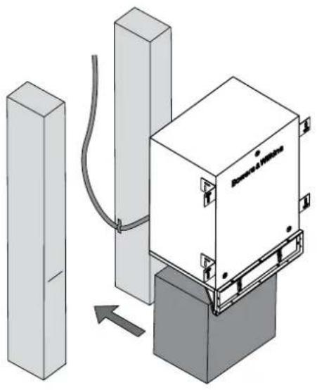
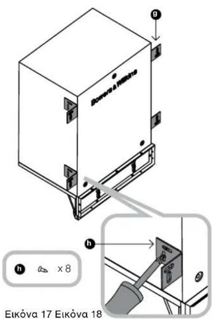
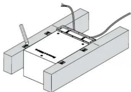
Screw the four L-brackets (g) to the sides of the subwoofer cabinet as shown using two No.8 x 12mm (0.5in) screws (h) per bracket. (Figure 17)
The vertical position of the brackets is not critical, but make sure they are flush with the front of the cabinet.
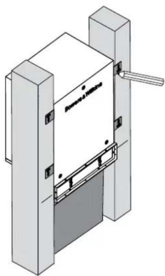
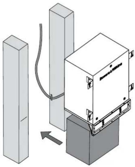
It is not essential, but it is easier to fit the subwoofer if you support it temporarily underneath to bring the louvre to the correct height.
Slide the subwoofer into the desired mounting position (Figure 18).

Figure 17 Figure 18
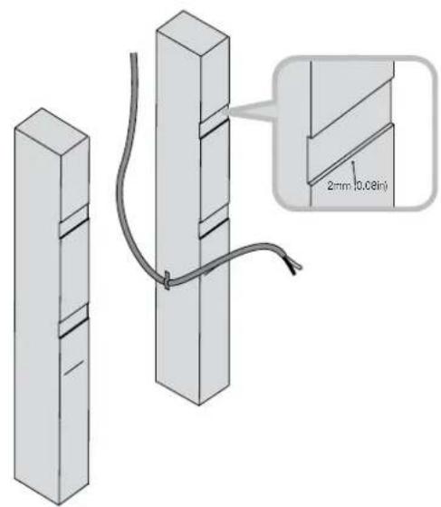
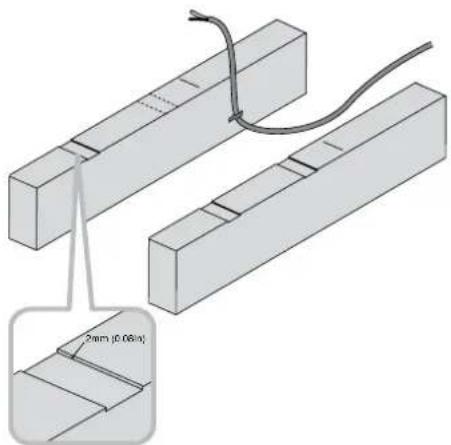
Mark the outline of the brackets on the front of the studs. (Figure 19)
Then remove the subwoofer and rebate the studs between the mark lines as shown to a depth of 2mm (0.08 in) so that the brackets do not bulge the drywall panel when fitted (Figure 20).
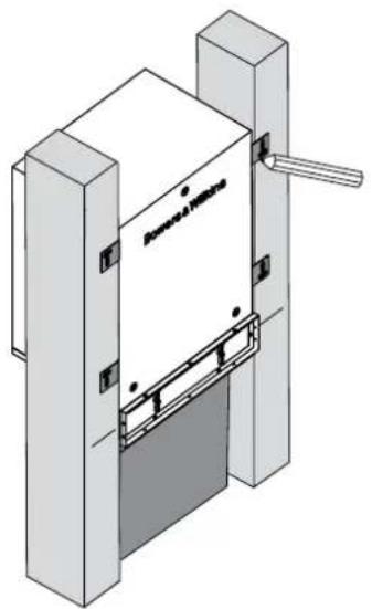
Figure 19 Figure 20
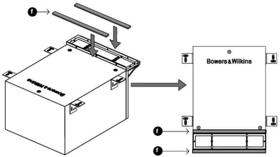
Screw the support bar (j) to the top of the cowl as shown using the three No.6 x 25mm (1in) screws (m) into the pre-drilled pilot holes (Figure 21).

Figure 21
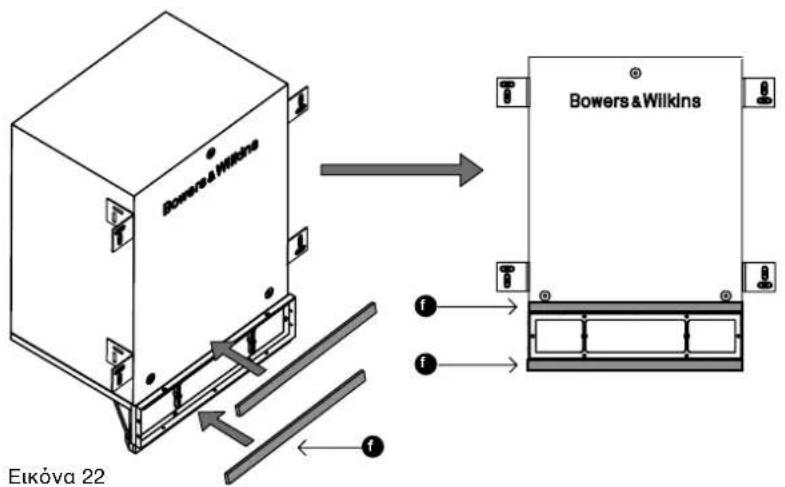
Remove the backing paper and apply the two self-adhesive gasket strips (f), one to the support bar and one to the cabinet at the other side of the louvre frame. These will bear on the drywall panel to avoid rattles (Figure 22).
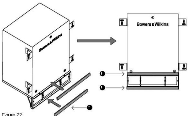
Figure 22
Bring the subwoofer close to its intended position. Strip the ends of the cable and connect it to the spring terminals, observing the correct polarity. Then secure the cable to the cowl using the cable tie to prevent rattles (Figure 23).

Figure 23 Figure 24
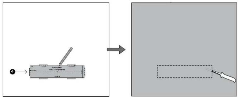
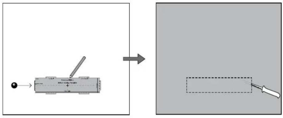
Use the cut-out template (e) to mark the aperture on the drywall panel. The six protrusions correspond to the outer dimensions of the louvre fascia and are provided to indicate necessary clearance. Do not mark round these protrusions, but rather along the dotted lines that cross them (Figure 25).

Figure 25
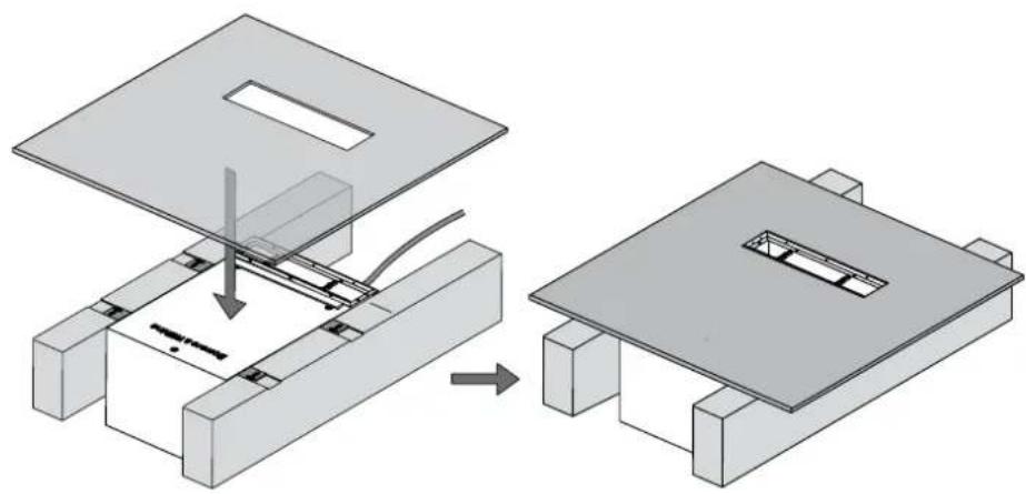
At this point, you may apply flexible mastic to the face of the subwoofer cabinet to prevent rattles against the drywall panel.
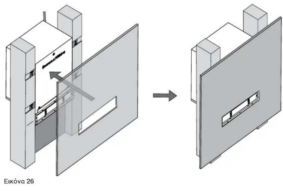
Fit the frywall panels to the studs (Figure 26) and apply the final skim coat.
Paint the wall at this stage and, if desired, paint the louvre fascia moulding (b) to match. The part will take all normal wall paints.

Figure 26
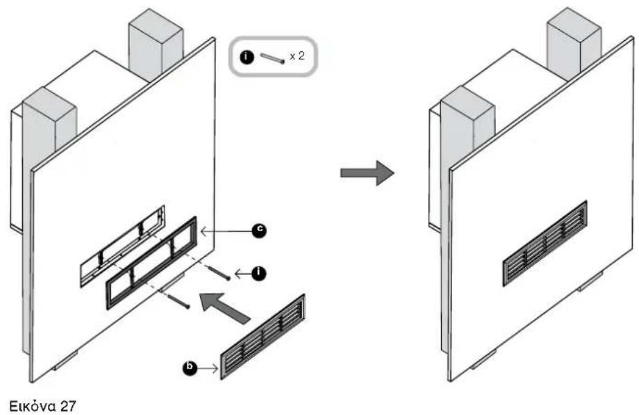
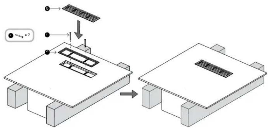
Attach the louvre (c) to the front of the opening and secure it to the louvre frame using the two M3 machine screws (f) through the two bars. Do not over-tighten. There should be slight bending tension in the two louvre bars, but the surround should not be distorted or the fascia will not fit correctly.
Clip the fascia (b) to the louvre (c) (Figure 27).
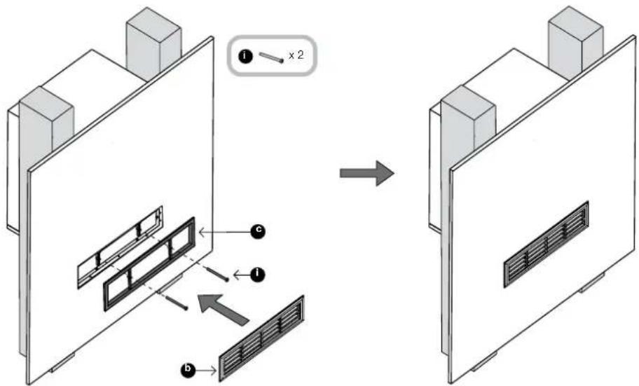
Figure 27
5 Installation under the floor
The speaker will fit between joists with standard 40cm (16in) or greater spacing, such that the visible louvre straddles the gap between them. A clearance of 25cm (10in) or greater behind the top of the joists is required.
The product is not recommended if the floor is to be covered by a thick carpet. Very short pile carpet, such as carpet tiles, may be accommodated with care.
Mark the centre line of the desired louvre position on the top face of the joists at each side (Figure 28).
Run appropriate gauge speaker cable to the installation point. Secure it to the joists so it cannot rattle, with the final tie point close to the marked louvre centre line near the bottom of the joist. Leave approximately 30cm - 50cm (12in - 20in) free at the end (Figure 29).

Figure 28
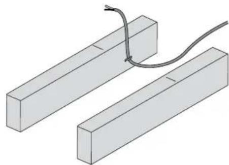
Figure 29
Attach the four support brackets to the sides of the cabinet as shown, using two No.8 x 12mm screws (h) per bracket. The lateral position of the brackets is not critical, but ensure they are set flush with the top surface of the cabinet when the cowl opening faces upwards.
Lay the speaker between the joists, supported by the brackets overlapping the joists (Figure 31).
If the joist spacing is too great to allow screwing through the brackets into the joists, a custom support method will need to be applied by the installer.
Align the louvre frame with the marks on the beams, making sure it is square to the wall and mark the outline of the brackets on the joists.
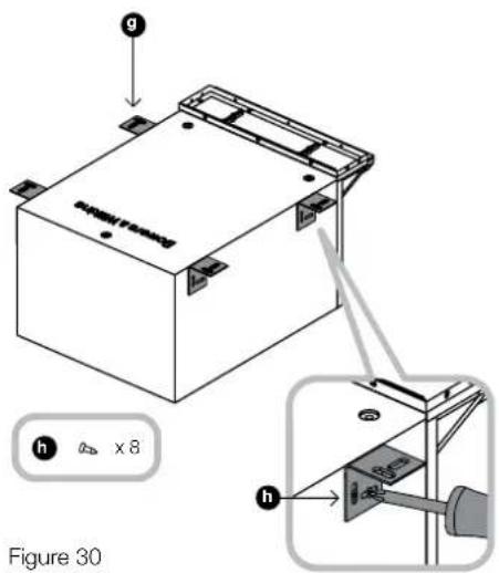
Figure 30
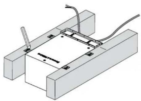
Figure 31
Remove the subwoofer and rebate the joists to a depth of 2mm (0.08 in) to accommodate the thickness of the brackets (Figure 32).
Screw the support bar (j) to the top of the cowl as shown using the three No.6 x 25mm (1in) screws (m) into the pre-drilled pilot holes (Figure 33).
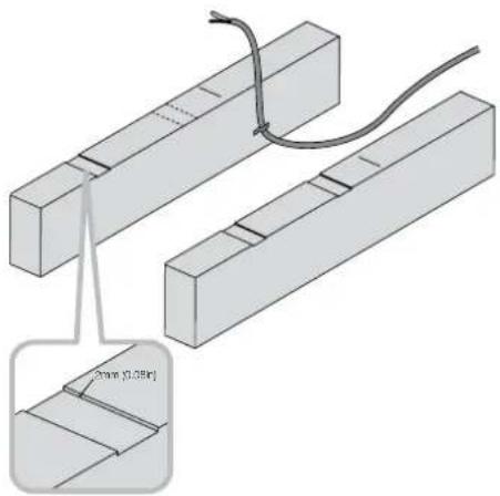
Figure 32 Figure 33
Remove the backing paper and apply the two self-adhesive gasket strips (f), one to the support bar and one to the cabinet at the other side of the louvre frame. These will bear on the floor boarding to avoid rattles (Figure 34).
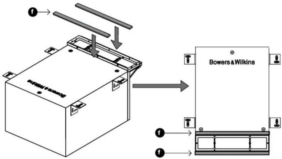
Figure 34
Bring the subwoofer close to its intended position. Strip the ends of the cable and connect it to the spring terminals, observing the correct polarity. Then secure the cable to the cowl using the cable tie to prevent rattles (Figure 35).
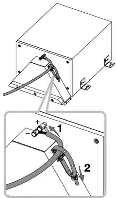
Figure 35
Place the subwoofer in position, with the brackets resting in the rebates, and secure it to the joists by screwing through the support brackets (screws not supplied) (Figure 36).
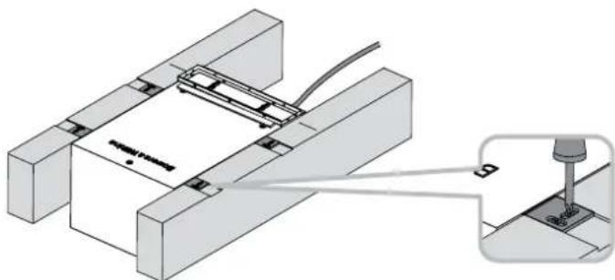
Figure 36
If using sheet flooring, use the cut-out template (e) to mark the aperture on the floor panel. The six protrusions correspond to the outer dimensions of the louvre fascia and are provided to indicate necessary clearance. Do not mark round these protrusions, but rather along the dotted lines that cross them (Figure 37).
ENGLISH
Figure 37
At this point, you may apply flexible mastic to the face of the subwoofer cabinet to prevent rattles against the underside of the floor surface.
For sheet flooring boards, fit the board with the louvre cut-out in place.
For strip planking floors, fit the planks around the protruding louvre frame
Where appropriate (see the comment at the start of this section), lay the carpet and cut a hole through to match the hole on the floorboards.
If desired, paint the louvre fascia moulding.
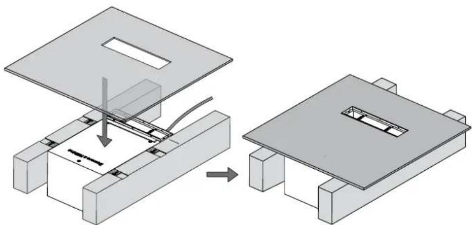
Figure 38
Attach the louvre (c) to the front of the opening and secure it to the louvre frame using the two M3 machine screws (i) through the two bars. Do not over-tighten. There should be slight bending tension in the two louvre bars, but the surround should not be distorted or the fascia will not fit correctly.
Clip the fascia (b) to the louvre (c) (Figure 39).
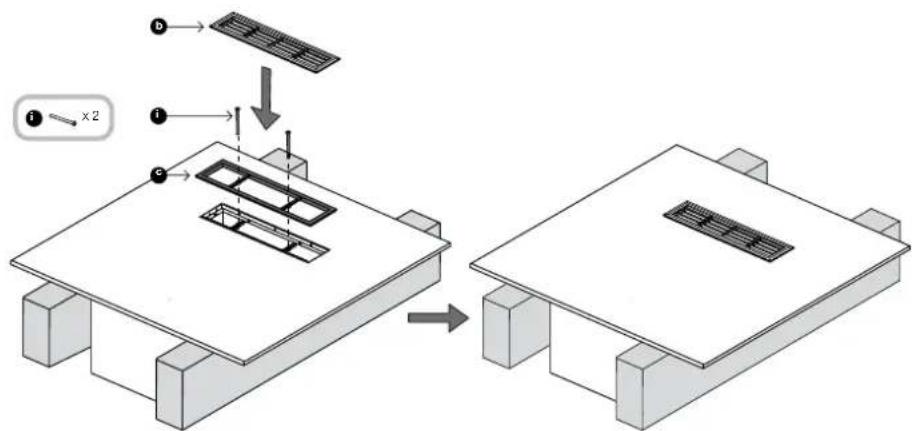
Figure 39
6 Installation in a kitchen unit
The subwoofer will rest on the bottom shelf of the unit and vent through the toekick panel below the door.
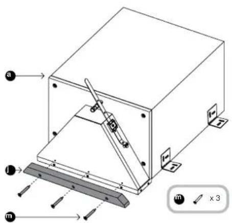
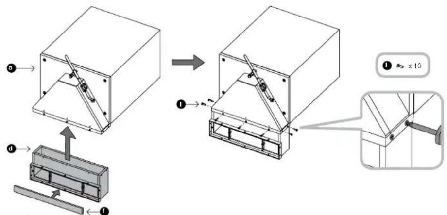
Remove the backing paper and fix one of the gasket strips (f) to the cowl extension, along the edge of its louvre frame.
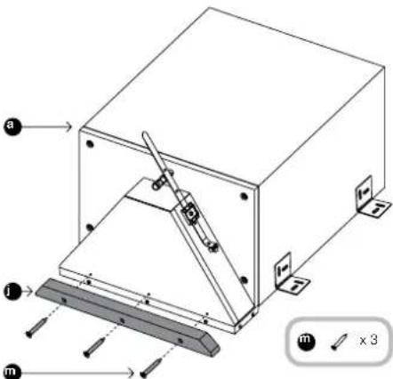
Attach the cowl extension (d) to the louvre frame on the main cabinet, using the 10 No.4 x 10mm screws (I) into the pre-drilled pilot holes (Figure 40).
There is a pre-fitted gasket on the louvre frame moulding attached to the cowl. This must be compressed when fitting the extension and the pilot holes will not line up unless the gasket is properly compressed.
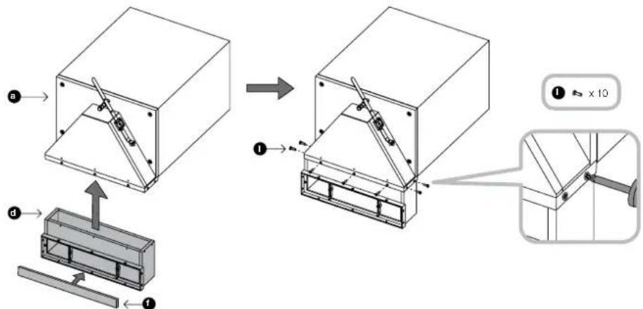
Figure 40
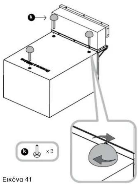
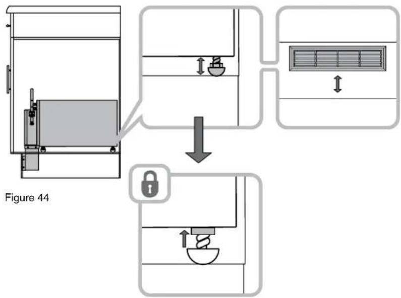
Ensure the locknuts are fully screwed down on the threaded stems of the rubber feet (k) and screw all three feet fully into the threaded inserts in the subwoofer cabinet (Figure 41).

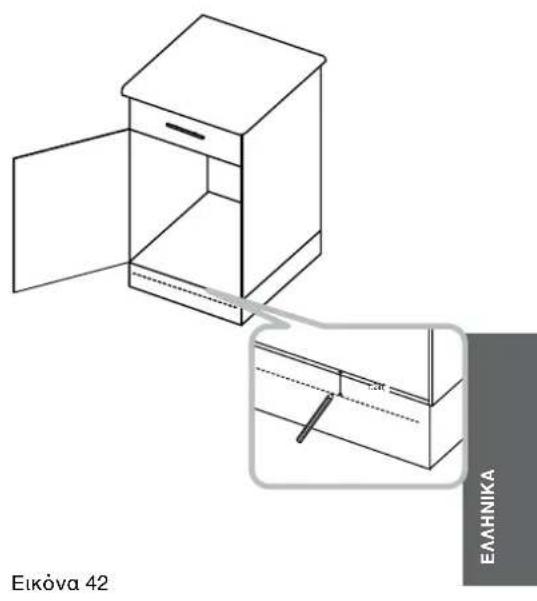
Make a mark on the toolck panel 30mm (1.2in) down from the surface of the bottom shelf. The top of the cut-out in the panel must not come below this line (Figure 42).
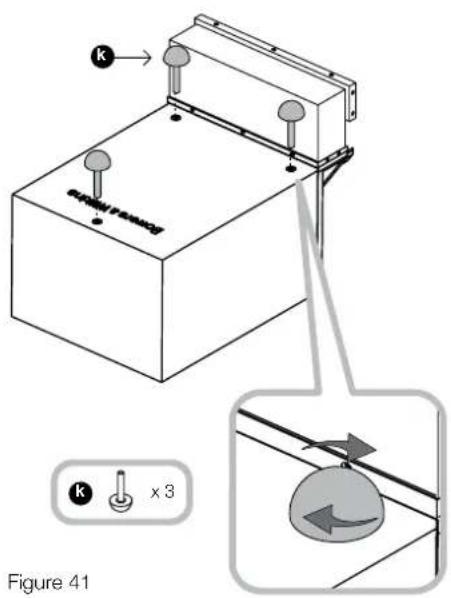
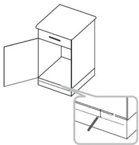
Figure 41
Figure 42

Using the supplied template, mark the cutout on the toekick panel as desired, making sure the top of the template is at or above the mark and that it is squarely aligned.
Cut the hole in the toekick panel and another in the bottom shelf of the unit to clear the cowl extension. The front of the hole in the shelf should be flush with the back of the toe-kick panel (Figure 43).
Run appropriate gauge speaker cable to the installation point.
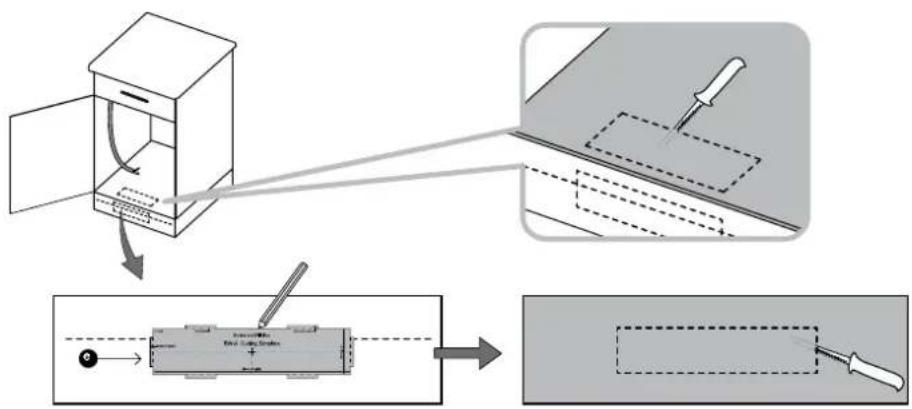
Figure 43
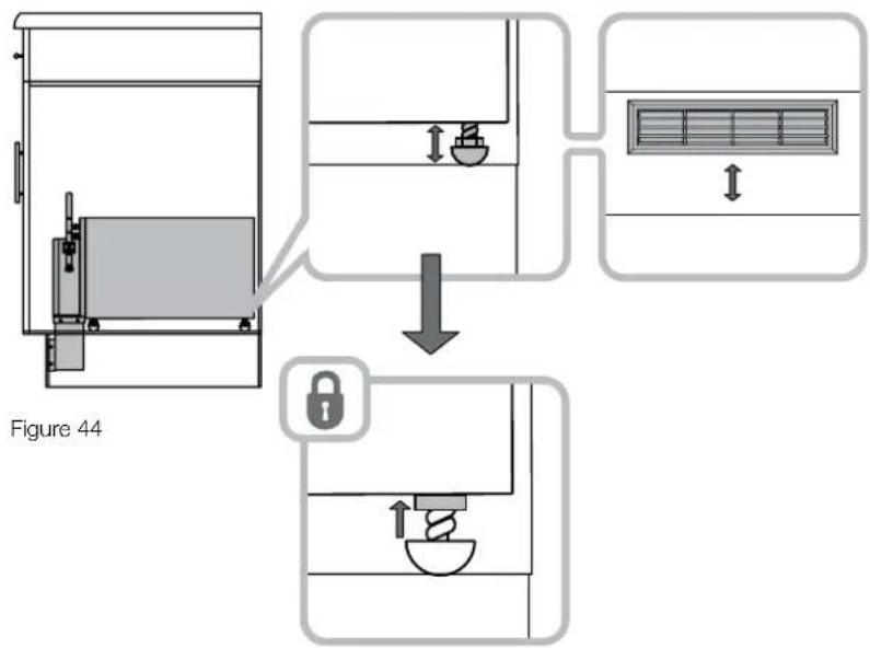
Place the subwoofer on the bottom shelf. Unscrew the feet as required to align the cowl extension vent with the cut-out in the toeck panel. Keeping the feet still, screw the locknuts up to the subwoofer cabinet to maintain position (Figure 44).
Strip the ends of the cable and connect it to the spring terminals, observing the correct polarity. Then secure the cable to the cowl using the cable tie to prevent rattles (Figure 45).
If desired, paint the louvre fascia moulding.
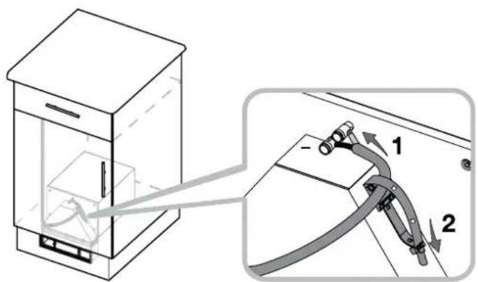
Figure 45
Attach the louvre to the front of the opening and secure it to the louvre frame using the two M3 machine screws (item 11) through the two bars. Do not over-lighten. There should be slight bending tension in the two louvre bars, but the surround should not be distorted or the fascia will not fit correctly.
Clip the fascia to the louvre (Figure 46).
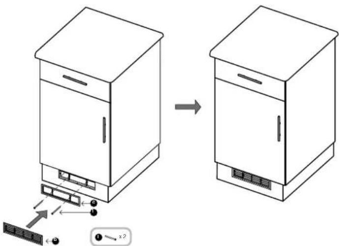
Figure 46
7 Running in
The performance of the speaker will change subtly during the initial listening period. If the speaker has been stored in a cold environment, the damping compounds and suspension materials of the drive units will take some time to recover their correct mechanical properties. The drive unit suspensions will also loosen up during the first hours of use. The time taken for the speaker to achieve its intended performance will vary depending on previous storage conditions and how it is used. As a guide, allow up to a week for the temperature effects to stabilise and 15 hours of average use for the mechanical parts to attain their intended design characteristics.
However, longer run-in periods (as long as a month) have been reported and there is evidence to suggest that this has little to do with the speaker changing and more to do with the listener getting used to the new sound.
8 Aftercare
The subwoofer should require no maintenance, other than to periodically remove and clean the louvre fascia.
If the subwoofer is mounted under the floor, periodically remove the louvre fascia and vacuum the cowl cavity to remove any debris that may have fallen through (Figure 35).
Eikova 15
Eikova 17 Eikova 18
Eikova 16

Eikova 19 Eikova 20

Ppaaoote Tn maapa otpiene (j) ony
onf eodou tou hou tou toutoyouep
xpanoiowvtaic tpcie bioe No6 x 25mm
(m) kui tihn unapxouoe pcune (Eikova 21).

Ekova 21
ApaipoteTo npoostateutiko xapti kai baIte Tc duo autokolntec eaaotikcs awpiocf (f).mu otynuapa otnpiaenckai tvn aann otyn aaan nneupa tyn pliaac. Oeaaotikcs awipiece Ta akoumouv tvyuyosavida oote va anopeuxthetain eauavion tviyuv kata tvn aeitoupyia tou unoyoupep (Eikova 22).
Φeptη Tny kajniva kovta ot θeon otepewnc TNC, STPIE TA akpa Tou kalwiou KAI ouvdoTe TO kahe akpo ME Toviatox Oelatpiwto akpodeknt Nau unapxei OTN Kauniva Tou Nxiou. Dwote npooohnT ovotn noikoteta kalwiou -akpodektuv. Tia va anofoyete uovtrououoc kat nV aeitoupya Tou auotmuoc aaoaiote to nepiaoejua Tou kalwiou ME to dejatiko Tou unapexi, yia auto To OKONO, Kovta OTouc akpodektec (Eikova 23).
XpnaonoiowvTac,av έeλeTe, to avtikeiEvooTou stnpieIy kainiva baIteTo unoyouΦepTOnVTEaiknθeONTEpeWOns Tou pnoexovTacwote oiywiec OTPiEncVa "0hukovouv"OTcUnoOoxecNou exeBnIoUpynei. Biodote TgYwicc OTPiEncOTc EmapveicotpeewocnTou (oi katalannLec BiEc dEv npexovtai) (Ekova 24).
Oav exete biwoke kavoviKa Tg wvies unopeite va aapaeote to avtkelevo opewncou nooyoep,av exete xpoonoinoei tetoia.

Eikova 23 Eikova 24
Xpmonoiote to natpv (e) ia va kojete to avovia yia tvy pilia otny uynooaioa (n oe onoiadnoite emapaveia 8a unapxei otny npoou). Ta eia"autia' nou unapxov oTo natpv avtioaoivou otny eEgtwepikni diaietpo tnc npoosic mc ypiiaq kal unapxov mvo ia va deixvou to anapaitto diakeve. Mny onuaedeiete to avovia me faon tvn nepiuetpo (tow autiwv) aaA me faon tic diakekouec ypaue cou oaknpovuv tyneipetpo tou npalaaoypaumou (Ekova 25).
Ekova 25
Se auto to onneio npoteivetai va balete
Eaaotik maotiyn otny eniapavaia tc kajinvac
tou unoyoupep nou a akouma atny
npoooun tnc eoxns, wote va anofoyete
tnv onuupuyia triyuov otav to nxeio 8a
Aetoupyei.
STpewto unoyouqo tO TO IOXU KAI OTNV OUVEXEA EYkataotnToV EINPAVA IVIPIaQATOC TOU ToIXOU (Eikova 26).
εαuτοσtáδio μnopeite va βαψeTe Tn póoαη nC unθoδxnc Kaδw cai nγ npooaŋ nTc ypliaac (b) wote to xpμa nTc va taipiaεν αuτo nC opoΦn. Fia to βαψiμo nopeite va xραμoηoIe oonoiδhntε ouvnθiaμevo xρμa.
Npooapuote to naiaio nyc ypiac oto avtioTOXO avoivya nou exei oniuynpythe 0nny npaooy nnc unodoxic kai aphiaiote to xpnnoiowvta c t duo bioe MC (I), mnu ophiEte uepBoIAkTo naiaio atc mnpae c otpeewonc tou. To naiaio ts ypiac npene i evai elaopa oevmo aa n nepieipoc Tou naiaiou dvnevi evai npapuoppwovn n Otpaewv.
KoumwoTe Tnv npooyn Tc ypiiaac (b) oTo maiao tnC (c), (Eikova 27).
5 Eykarataaon katw ano to dan
To unoyoupe npoei va taipiaEe ietaE duokw nou exou anoataoeta eTuoc ion neyauTe np 40cm (16in), taoi wate to eufpce npoc ts ypiac va yepuwe To kevo metaTuoc.Babo cyealutepo twv 25cm (10in) -to to aw eniteo tow okaipw, anaireiial ia va npopeei va xwpoei kajniva tou unoyoupe.
AutoTo nxeio dev npoteivetai va ekataotatheta KATOWI NATOWATA NOU ta kaluntovta ano Bapu xali. Aenra xaia muopei va xpnaouoinouv me uveon, apkei mayn kailntouv tyn ypilia.
Ta naeupa taw emapavew stepeownc Tou unoyouep (n ookv) taepn ta ypaumn nou Ba onmaeuei tn peon tn cyiac (Ekova 28).
OSeUte kaWio nXeiW katalannc diatounc
OTo onueEvkataoanc. StepeWote to
Owot atic eniapaviec stepeownc wote va
Anoeuxovu naiovol triyoi Evw to teAiko
onieo stnpienc npenei va pkioketai kovta
Ot keVtpo Tc ypliaac.Aphiote nepinou 30
Euc 50cm (12in-20in) nepioeua kaWsiou
(Eikova 29).
Biodote Tc Teoepes ywies cTnpiEg (g)
ota naeupa Tnc kauinvac Tou unoyouepe,
xpoiounovtac du bides No 8 x 12mm
(0.5in) (h) va oTpeewote Tnv Kae
yvwa. dEv evai kiaio o aiacec ot npie
va tonoetnbouv anoluta kaeta aalaa
beaiowte troe xpovta "npoWto" me Tny
npooun Tnc kauinvac Tou unoyouepe, otav
n Edoocktovwoc Tou aepa Tou unoyouepe
koita npoc Ta naivw (Eikova 30).
Aokujimote to nxeio etoi wote oiywiesc otepewcnva to otnpicouv otic dokouc (Ekuova 31).
Av anooraonetaTuovdoKovivaiyayaln kaiev enptenei myotepewanTc kajiniva cte Tycwic otpienc evac nepapevoc Eykataotnc penevi va envoaeeav biapopetko tropono otpienc.
Euoypauiate to nlaio tnc ypiiaac me ta onaia otokouk kalbaowte ni civai oatayviiaevn oxon me ta opia tou oomegaiakmu teokoucstepewnoc
Enjaedeys ta onueia nou akoumouv oiywies otdoekouc n otic enuapeiveo atnpiecnouo atepewei ngkainva.Aaipoeote tvkajniva kai dnoupnyote "auakia" (anaitouveo 30oc 2mm) wote otav biowoui oywics va npirepeeouv anotnv enuapieia stpienk kai va npy emoizouv tvn tpewen ts enpuaeiaos Tou danedou (Eikova 32).
Ppooapuoote Tnunapa OtnpiEnc (j) Otnv
on EeOou Tou nou Tou untooyoupep
xpaonoiowvtaic Tc pteic Biiec No6 x 25mm
(m) kaii hnon unapxouoeTpune (Eikova 33).
Ekova 28

Eikova 29

Ekova 30
Eikova 31
Eikova 32 Eikova 33
Apaieote To npoataeutiko xapri kalbaTc Tc duo autokolntec eaaotikec awipoe (f), ma otnpa napa onpnc kai nn aann aaan naupacn ypiia. O eaotikicawipoe 0a akouinov tv eniapavae tou danedou wote v anoepxtheta i emqavion triyuv kaTnv leioupyaou nooyouep (Eikova 34).
Ekova 34
ΦePTE mV kaJniva KovT aO n θeON oTepeWOnC TNC. STPIyTe TA akpa Tou KAALWdiou KAI ouvBeTe TO Kaθe Akpo ME Tou AVtioToXo ELaTpiwTO akpOeKTo Nou unApxei OTV KaNlva Tou NxEoiu. AwTe pOooN Otv OwOTo NOLIKOTTA KAALWiOu -akpOeKTuV. IaVa anofoye AuvToviaouc KATA TIV λειToupyia Tou OuaTjmuoc aQphiAIOte To nepiaeaMu Tou KAWdiou ME To Deμatiko Tou unApxei YIA auto TO OKONO KovTa OTouc AKpOeKTEc (Eikova 35).

Ekova 35
BaTe TO UTooyouΦeP OTNv TEaKn θeO nTepewonc TOn npooexovtac wote O ywive cOthpiEnc va "Oaukowov"OTC uTooOboxec Nou Exete NDoiupynei. Biodote Tc wiyec OthpiEnc otic enuapavteie opeewonc Touc (OI KAtaaAaNc BiEc Dv npexovtai) (Eikova 36).

Eikova 36
Av n eniavia tou danou anoteleitai ano
fllaa (eeyalec eniavieec) xnpaonoinote
to natpv (e) yia va kovte to avoyua yia
tny ypia any avtiotayn eniavia tou
danoeou. Ta eui "autia" nou unapxov sto
natpv avntoioxuov anv ny eEwtpekn diayetpo
tnc npdoounc nyc ypiiaac kal unapxov mvo
ya via daixyovu to anapaitno diakveo. Mny
onmaedepsi to avoyua me Baon tv nepietpo
(tow auivaw aa lae Bao n tic diakekouevc
ypauec tou oaknpovuvv tv nepietpo tou
napaalnoypaumou (Ekova 37).
Eikova 37
Se auto to onneio npoteiveta va balete
elaotik naotiyn any eniapaveia tnc kajinvac
tou unoyoupep nou Ba akouunna enipaveia tou
danébou, wote va anopuyete nvy dnoiupyia
tpiyuovotav to neeio ba letioupyei.
Av to natawa anoteleita ano fuaaa tonoetntane npwta to fulao oto onioeXeKo8e1 to aoivya Tc ypiiaas.
Av to danoe 0a anoteleitai ao avidec n napke oTepeowte npwa ta komuata yupw ano tvyipia.
Av xpeiaZeta (Beite ta oxia otyn apxn Tou Kepaaiou) bale Tny moketka kovotac To katalanno avoivya yup ano nyn ypia. Tepeewto unoyoupe oic dokouc kai otnyuveia evyataonte nyn eniaviaePhiipioaTOC (Eikova 38).
εauro to stadio μnopeite va βaetae to naiao tro yipiaac wote to xpma tnc va taipiaei me auo tou danéou ntc μoketac. Tia to baipua unopeite va xpanoanoinae t onoiohnotoe ouvngiaevxoewa.
PpaoapooTe Tnlaio Tnc ypiiaoc 0to avitato x aoiyma nou exei dnoiuopynthei 0to danoe kai aphialote To xnpaunoiowvtaic tio duo biEcM3 (i), mnu ophiTE unepoikata to naiaio otic unapec opeewonc Tou. To naiaio TNC ypliaac npenei va eivai eaappa oipievo alna nepiuetpos Tou naiaiou dev npenei va eivai napapopwve n otpaewevn.
KoumwoTe Tny npooyn Tc ypiiaac (b) oTo nlaio to c(c), (Eikova 39).
Ekova 38
Ekova 39
6 Eykataaon evtoulani kouzivaac
To unoyoupe npoei va akouma oTo KATW EPOC EVOC papiOI OE vva Vtouan TNC KOUVC.HOM EKTOwON Tou epa TNC KAMIVAC TO unoyoupe npoei va EYkataoataeI OTO KEVO XWO, KATW ANO To Vtouan KaN YpIA VA OTEPEWTheta npooNO TEAIOOANTKO npoPIA (muCA) OTO KATU MEOPC TOW VtouanuW.
ApaipoteTo npoatautko xapti kai Otepewote TN mla eaaotkn Lwpiida (f) oyn PnoeKaonnpaooync Tc ypiiaic, aTO xeiooc Tou naiiou nTc ypiiaic.
Ppaoapuote Tny npoeKaon npoapauoyn Tnc ypliaac (d) 0to naiio Tnc ypiiaac otyn Kaipinova unoyoupe, Biowovtac tic 10 biiec No.4 × 10mm (I) otic tpueneou hon unapxouv (Eikova 40).
Ynapexi eva apwdes xeiloc oTo nlaio TnC ypiiaacou eivai npoapuouevo otny npoeKaan npoaoapoync tnc.Auto to appwdes nlaio npenei va oumuotei otav n enktaon nnpoaoapoync biwveTal me tic Biiec.Ta duo konpatia th a eliva owotau ouvapuoynueva otav to appwoe nlaio 0Ta exei oumuieotei apkeTA.
Bbaowte na ta aegiaa oaoaiang exouv nhpwc biwthetai oto anteipomega nou npae xta eaaotika nobia (k) kai biowote ta tpi eaaotiknoida otaeipwata nou npayouv otynbannou unoyouep (Eikova 41).

Kavte eva ona 30mm (1.2in) katw ano to kata wepoc tov tvouanoiou, oto diakooantko teleiaowatvvtouaniw. To naw wepoc tov kujiaatoc eV npenei va enepva tv ypaumnou onaedepsiate (Eikova 42).

XpnoonowvTac to natpv onmaedewte TcTpunc.Beawthetapioc to naW wepoc Tou natpv elvai naW ano To onaoui exetkev nponyouevw, Baeawthetae enicnwc ta 5u oiaiaou onmaedewte evai euyupmaqeva metaEtuoc.
KoTc Tc Doo Tpunc wote va mopei va n npoeKaon npoaapuyn Tc ypiiaac, H eepoc naeupa Tc Tpuac o p aip npenei va eivai "pao" To tiaw hpcotou navek (Eikova 43).
Oeute kawio nxiowv MEkataaann diatoo oonueyekataotaonc tou unoyouep.
Eikova 40

Ekova 43
TOnoTeIeTo unoyoupep oTo paftou vTuaiuO. EbiowTe Ta eAotka noidia 0oo anateiTa wote va uBuypaiaei Te nV npoektaanpoaaogyoNc Tpyiaac me Tn Tpua nou exTe kavei otnv "muca" Tou vTuaiuoi. KpatovTac ta eaatiknolia Otaepa, biWto Ta naEuaiaoui nu aopalicouv To anepiaw, oote To unoyouepva napaevei Otn Theon Tou (Eikova 44).

EcnnKaKnx-To DeTaneH He Xbatae TnN OTHOBpeXdHbI, 06paTntecb K CBOEmy DInnepy.
2ПуMuEHeHnA
IMEOTC YETbIe BO3MOXbHbX BaPnHaTApnMeHeHnK,KaJdbN H3 KOTOpBxpacCMATPBaeTcB CBOEm paJaJe:
TOnToNoUHbI-TonbKO BHObblx Domax(Figure 2) NepexoDnTe BPa3dE3.
BCTPOIKA BCTEHY -TOJIbKO B HOBJX DOMAX (Figure 3)
PepexoDnte B Pa3dE 4.
Poi nonom (Figure 4)
PepexoTeBPa3dE5.
BkyxohHOn Tym60ye (Figure 5) NepexoDnTe B Pa3dEn 6.
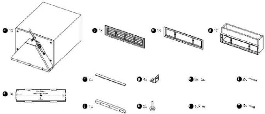
Figure 1
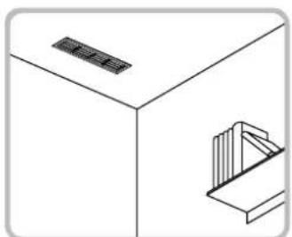
Figure 2
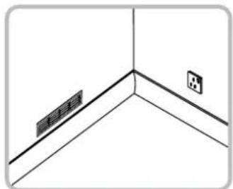
Figure 3
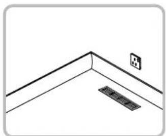
Figure 4

Figure 5
3YCTAHOBKaBNOTONOK
Cabbyep pa3meaetcMexy deporopokamco CTAnapThBM paccTOrHnEM B 40 CM (16in)Hnn6oBe, TaK TTO BmIMa Nactb erO xAnIO33anONHRe 3aOp Mexy HmN. Heo6xmoOCTABNTCB6OHOH npocpAHTBOB 25 CM (10in)Hnn6oBe Mxq Kopyncom cabbyepa HnHexneonepeuHO neporopkoi.
OTMeTBe ueHTpaIbHyIO ocXeNaemoro
pa3MeEaHJIHaJIo3Ha 6oKOBn NOBepxHOCTu
peEROpOdoC kKaDD CTOPOHb.CdaneIte EBE NometKN Ha 06eHX NpeEROpOkaX Ha BcICote
PpNbNtENbHO 75 MM (3in) n 380 MM (15in) OT
ceHTpa XaJIIO3n -Inr yOrIkoBbIX cKoB, KpEnrauxk
kopnyc(Figure 6).
PnKpENITEeTbIeL-06pa3hBIXCKo6bl(g), KAKNOKa3aHOHaPCyHKe,KBHYTpHeHH BEPTNAJIbHOHTOPOEPEPERODO (UpyPnI IAN3TORE HpeINARAOOTC),Y6eDINBIMCb,CTO CKo6blCTOIT NOI pRmMbIg YTMOM 3aONDnIO C DHOMNEPEROPDOK.
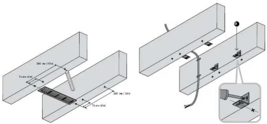
Figure 6 Figure 7
PpONoKHTe KOLOHOHbIe Ka6eHn Heo6xoDMOrO CEeHn DO TOKn YCTaHOBKn.3aΦHKcNpyTe Hx Ha NpeEROpOKaX, TaT QTOb6 OHN He Bn6prOBaJI, pRn 3OM NocNEHNR TOOKA KpeJIeHn DOJKNHa 6bITb 6m3KO K NOMeEHNO CEHTPaJIbHO JINHn XaON3 OkO NO BepXyUkN peEROpOKn. OctBaTbe CBO6ObHn KOHeu Ka6eHn DInHO nPb6nMNTeBHO 30-50 cm (12in-20in) B KOHe (Figure 7).
PnKpEnIe onOpHb cTepeXeHb (j) K XOMyTy, c nOMOuBIO TPEX 60NTOB No.6 x 25 MM (m) n npEaBPInelbno pocBepenHehBx OTBepcTMy (Figure 8).
CHIMITE 3aunTHbI cnoB yMaHn HANOxITe
DBe CAMOKNueXHcYyNOHTNEbHbIe PpOKnAKn (f)ONDa HOnPbN CTepKHe, aDpyrHy-Ha
KOpNyc C dpyro CTOpOHpaMbI dny KAnIOZn.
3Tn peshOBbe PpOKnADKn CNYXaTb Dn
BbONPOJINmRnCOKAPoTHbIX naHEne, YTObbl
npedotBpaNTb Nx dpe6e3r (Figure 9).
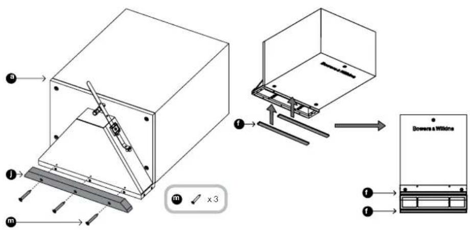
Figure 8
Figure 9
IpoHIMnTe cabbydep TaK, TTObO bOn Ner, KaK
NOKa3aHO h pCnYHe, k HcTbePle L-06pa3hBx
CKoBb. EcnpacToTHMe MEXypepePOdoKAMn
CNiUkOM BeNIO, TTObbl MoKHO bIoNo I npOyCTtB
UpyuMb Hepe3 CKObbl NonaTb B KOpTyC,
HCTaJIATOPy notpebyetc npDymTaB dpYro
NOXDOHMI MeT OKe PKNeHHA.
COBMECTHTe CEHTP BbIXOHDbIX KJIIO3N C METKAMn HA nepeRopOdkax N BbIPOBHRIte IX NOJXEHME NO CTHEM.
3aKpENNTe KOpNc B 3TOM NIOJKeHN C NOMOJIbH OyPmOB cAMOpEeOB No.8 x 12 MM (h), npOnyueHbIe HpeE L-06pa3Hbe Cckobbl n 3aBnHbMaEBMx B KopNyC (Figure 10).
PamkaXaJIHO3N6bYdET npn 3TOM BbCTynatb 3a HIXHHe NOBepxHOCTN nepePOdoK.
3aHCTNE KOHbI KaBEn H CoeHNHTe INC npyHHbIM paBemAMn HA KOpnyce,coNIOdA npn 3TO TON NpRHOCTb.
TObbI npEoDtBpAtnTb dp6e3r, 3akpenite NlwnHn KOHeL KabeLa n MOnOuBbO CTaRKK K caSbyepy (Figure 11).

Figure 10 Figure 11

IcnoIb3yIte w6bON (e) dIra TORO, T06bl
HAMETINb KOHTyp IPOEMA BHNCKoPATOHO
nITte. 1eCTb BYCTYNOB W6bIOHA COOTBEcTBcyOT
BHEUHIM P3aMEpAM peWETK C XAIIOHNI
CdEHaBI ToJIbKO DIAI TORO, T06bl NOKa3aTb
Heo6XoDMbIe rabapNTb. He p3MeayIte KOHTyp
no 3TNM BtCYNam, a oBeDInTe YepTeK No
NYHKTIpHbIM LNNHM, KOTOpB Ix OTCEKAIOT
(Figure 12).
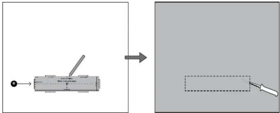
Figure 12
Ha 3OM 3Tane Bbl MoKTe HaHECTM MArKyIO
MACTNKy HnIeBvO NoBepXHOCTb KOpNyca
caBByFepa,HTo6bl npEDoTbPAITb dppe3r 06
NOTONHbte naHEn.
PnPKpENTE rncokaptoHbIe naHenn K NOTONCHBm npereopokam (Figure 13) HNAHECNTE OKOHATEnbHyIO wNAKJIeBky.
Ha30m3Tane nokpacbTe noToNOKn,ecnn XOTHTe,MOKTe BblpACITb MOJINHr peWETKN KaHO3n (b)B TAKOn JKe UEB.TaTeJbXopoWO NOKpBaETcO bOHyHBM KpackAmn DnCTEH.
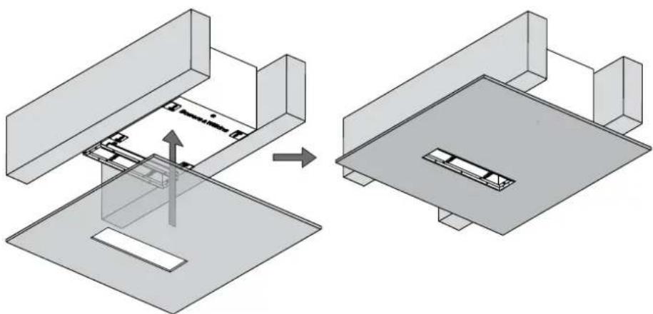
Figure 13
PnctabTe Xaio3n (c) Cpeepn K npoeMy n npnpenrteHX k PAMKe C noooub DByx B0ntOB M3 (i) nponyueHbX cepe 3de neonepuHbI. He nepetraBaiTe 3tn BoNTb. Dae nonepeunHbI dOnKbI cTneKa npOrHyTBc, HO xk OkpyKeHe He dONKHO NCKPNBtCBa, HNahe pAMKa He CoBNaTe C Xaio3n.
HaJeHbTe XaJIIO3n (b) Ha NmUeByIO nAHeIb (c) (Figure 14).
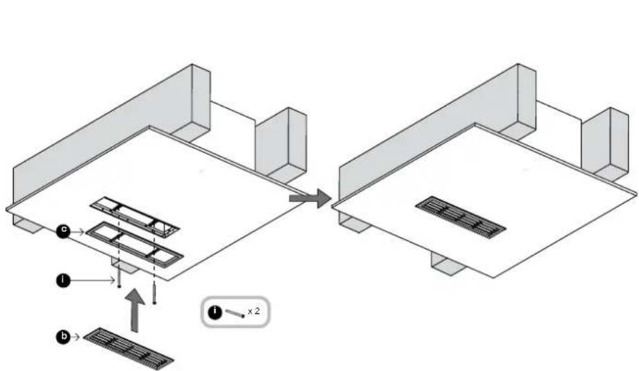
Figure 14
4 YctahOBKa B CTeHy
Ycabbyepa CmNkOM6nBsaA rnybHa. 0TObb OHymeCTNUR B cTaNAPTHOE 3aCTEHNO pnoctpactHO p3aMPOM 100 MM (4in),Ondako ERO MOXHO BCTPONTB 3aKa3HyO MeBEN Hnn yHna, NOxOaAMn no rnybHne, DE mKdy nepeopopkamn nCtEHKAMn IMeETCR CTaNapTHOE paccTOrHHe 40 CM nnn 6oonee
B60bnHCTBe CNTyaCm,BNHMnAR YactbpeueTKDolJXHa HAXOuTbCBAHXKHeYactnCTeHbI,PNMO HaIINHTycom.B TAKOM CnyaeKOPync CneJeYet OPOHInpObaTb BxOxDblMpactpy6om BHN3.
OTMeTbTe ueHtpaIbHyIO ocB JKeJaEMoTO
pa3MeueHnRA XaIKO3n Ha fpoHTaIbHO
noBepXHOCTn NEperOpOdoK C KaJDo CTopoHbI
ca6ByepeA (Figure 15).
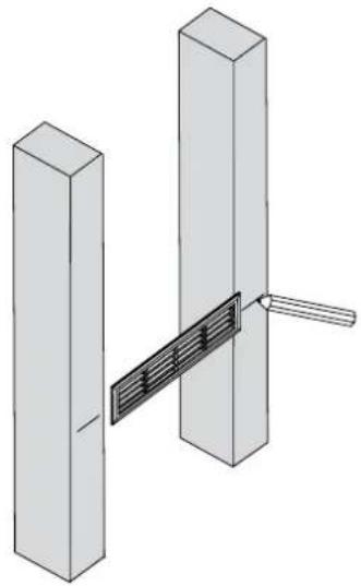
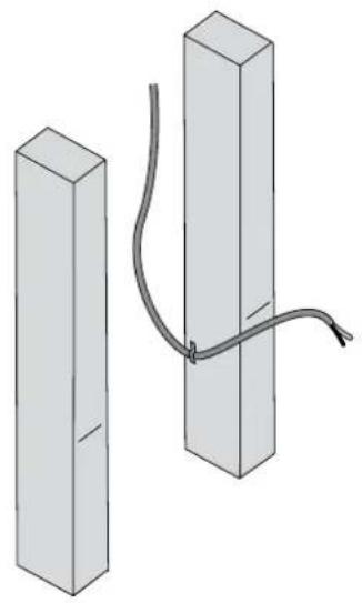
Figure 15
Figure 16
Плрохкге КОLOHOhBHe KAbEHN Heo6xOdMOrO
ceHEnI DoToKIn YcTahOBn.3aФнКcHpyTe
HX Na PereporDgKAn, TAK Tc0bI OHN
HE BnOpRoiBaII, npi STOM NocEgHnR
TOHka KpeJIeHn DOnJHn 6bIt bSb3KO K
nomeHHeNo CEHTpaIbH NoHHnKJaIO3n.
OCTaBte CBo6OdHn KOeHn KaBeHnДlnHOH
np6Ibn3ntelbHo 30-50 cm (12in-20in) B KOHee (Figure 16).
PnKpEnTe YbIpe L-06pa3hIx cKo6b (g), kak NOKa3aHO Ha pncyHke, K 60koBbIM NoepBXHOCTM cABSypeca NOMOByDx bpywnob (h) No.8 x12 MM (0.5in) Ha KaJdyIO cKOby (Figure 17). PaONOKeHcEe CKO NO BEPTKaJIH He KpTNUHO, ODAHO y6eINTEcB, YTO cKObCTOAT 3ANOIIIO C qPOHTANBOH NNOCKOTBo KOPNYCA.
3aada na noTROHKn uCTAHOBKn cabbypepa
6bnerhaetca, eCNbl BbpeMeHHo NOonpente erO
CHN3y HcHnHbYb TaK, YTObI peWETKaJANIO3n
OKa3aacBa Ha HyXHO BbICOTe.
3aBnHbTe cabbyep Brny6b B kenaemoe nonoKeHne dna MOtXka (Figure 18).
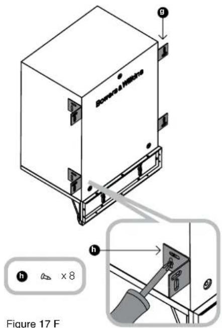
Figure 17 F
igure 18
HAmEtBTe KOHTpybCKo6 Ha φpOHTaJIbHbIX CTOpOHax nepeoropodok. (Figure 19)
3aTEM BbHbTe 6oPbHo c6Byepe H bBdoNbTe BneperoPckx No npOpeyHeHbIM nHHaR yrny6bHa Ha 2 MM (0.08 in), KAK oKAsaHO Ha pCNUHKe, TAK YTO6bCKO6b He TopaHIn NHX npN ycTaHOBke (Figure 20).
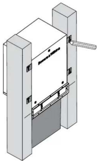
Figure 19 Figure 20
PnKpEnTe onOpHb cTepXeHb (j) K BepxuKe pactpy6a C NOMOuBIO TpeX 60JTOB No.6 x 25 MM (m) (1in), BCTaBNEHHbX B npeBaPntbHo npocBepENHbIe HAnpaBnHOUme OTBePCTra (Figure 21).
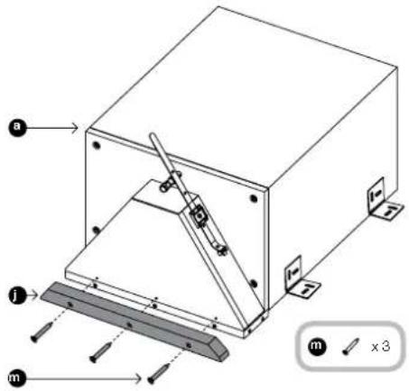
Figure 21
CHMMTE 3aunTHbI cnoB yMaHn HAnoknTe
DBe CAMOKNEUxCYNyTNOHTENbIe PpOKnAKn
(f),ONDy HnOPNbI CTEpKHeB, aDpyrO-Ha
KOpNc C Dpyro CTOpHObl pAmbl dna KAnIO3n.
3tn peINOHbIbe npOKaNkDn CnyKaTb Idr
BbPON3JIuMn RnHcOKAPTOHNbX NaHeJe, TTo6bl
npedOBpaNTb Nx dpe63r (Figure 22).

Figure 22
YcTaHOBHTe Ca6Bycep no6m30ctn ot HAMeHHHO rnoNOXeHHa 3AChTE KOHbI Ka6BeHnCeOeMHNTx C pnyKHNHbIMpa3BeMaMHa KOpNcyce,co6JIOaI npn 3TOM nonAPHOCTb. Yo6bI neoDTBPaTINb Dpe6E3r, 3AKPeHnTe NMIHHKOHeu Ka6eHa ca6BypeC nOMOsbI cTAAKKn (Figure 23).
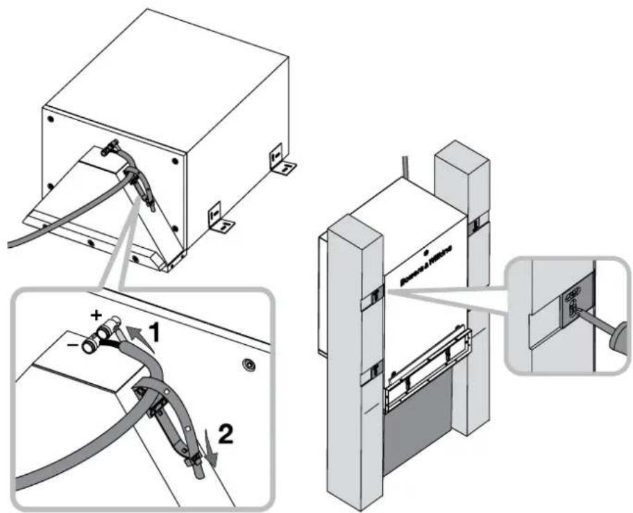
Figure 23 F
igure 24
McnoIb3yIte w65nOH (e) dNr TORo, YTO6bl
HAMETINb KOTyp npoema BmncOKAPTOHHO
NAHEIN. WcTeB BcICTyno 8a6NoHA
COOTBeCTBYOT BHEUHM pa3MePam peWetKN
C KAnHO3 IN cAenAbH ToNkO Dn TORO,
YTO6bl NOK43a7b He06XoMMbe Ra6apNTb.
He pa3MeuAIte KOHTyp NO 3TM BcICTyAM,a
OBBeNTe HcTepK No NYKTUPhIM NINHM,
KOTOpBE IX OTECKAOT (Figure 25).
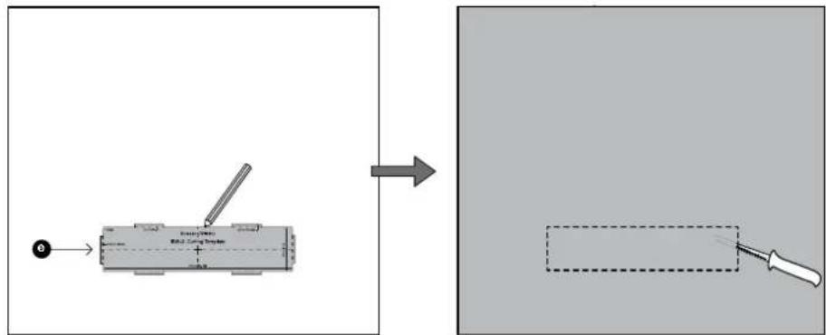
Figure 25
Ha 3TOM 3Tane Bbl MoXeTe HaHeCTn MaRkyo MaCTNkHa NJIeBByo NOBePxHOCTb KOpNyca caBbYpepa, YtBbI pPeOToBpATnB dpe6e3r 06 rnnKocAPToHnBie naHEn.
PnKpEnIte RnncKaTOnHbIe naHEn I cTeHHbIe NpeRopOaKam (Figure 26) nHaHeCte OOKOHaBHyo uNakNeBky.
Ha 3TOM 3Tane nOKpacbTe CTEHy n, ECNI XOTHe, MOXETe BbIKPACNTB MOJINr PEWETK KANIO3n (b) B TAKOJI KE UEB. 3a DetAIBXPOOLO NOKpBaIEcTc OB6HbHMKn KPACKAM DnCTEH.
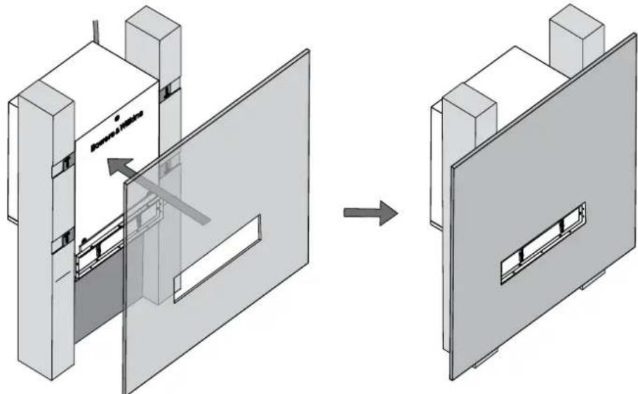
Figure 26
PnctabTe Xaio3n (c) cnepein K npoeMny n npnpenrte HK pAMKe C noMOuBb DByx B0ntoB M3 (i) nponyeunthe Xepe 3Be Dne nonepeHnh. He nepetraBaiTe 3N bOHTb. Dae nonepeHnhb DonKbI cnerKa nporHyTbC, HO xk OkyxeHne He DonKHO NcPKBnTBcR, HNaYe paMka He CoBNaTe C XaIO3n.
HaJeHbTe XaJIIO3n (b) Ha IINIeByIO nAHEnIb (c) (Figure 27).
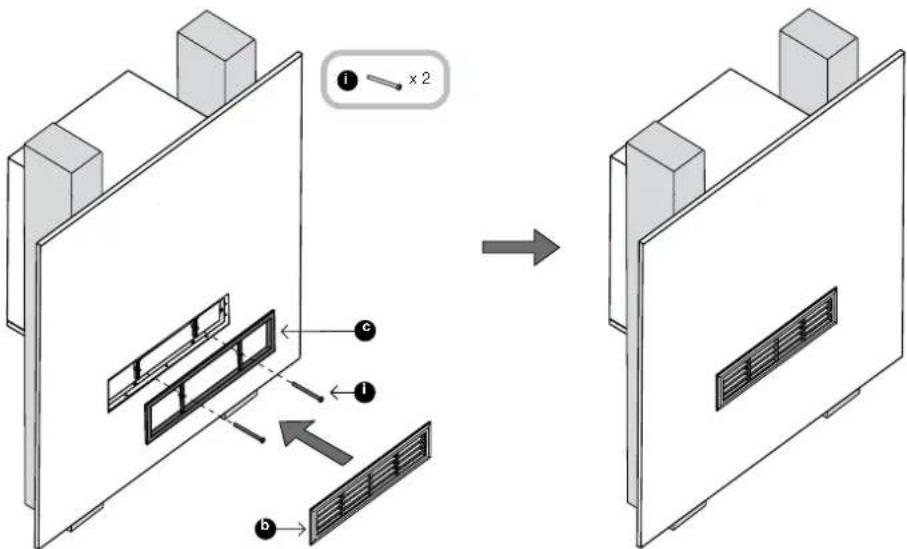
Figure 27
5 YctaHObKa noq noJOM
CabbyepymeaeTcMxMypeperopdkamm coCTAHAPTHIMpaccToHnEMB40cm(16in) nn60nee,TAcTOb6uINMaMAaCtbpeweTkn KaIO3IaONHnIA3oP Mekdy HNM. Heo6xoJIMO NMeTB rny6hHy nOd nONOM B 25cm(10in)nn60neeOTBepxneNPOCKOtn neperopodok.
HepeKomeHdyetyc yctahabnBaatcbabcepep noJ
noNOM,ecNI NO BYET NOKPTBTOCTbIM KOBPOM.
MoxHOxIOIb30BaT BTOK KOBpbl C OeHH
kopOTKM BOPCOM,HoC 6OJIbIoO OCTopoXHOCTbIO.
OTMeTBe YeHtpaIbHyO Oc bKeJaEMoR opaMHeNHa KaIO3n Ha cpoHTaBHO NOBepXHOCTn NpeperopOdoK CKaKDo CTOpHO bCaByePapa(Figure 28).
IpoJOKnTe KOJHOOHbHIE Ka6eHN Heo6xOaMIMOcreHeHDoTOKcYCTaHOBKa.3aDfNcHpyIteNXHaNEpEROpOdKaX,TAQTO6bO HnEHBeBnPbPOBaHn,piN 3TOM NocEeHnToKa KpenJIeHn DOJIKNa Bb1b 6JIb3KO KNOmeHHoN CEHTpaBbNo JINHnKJALIO3N. OCTabTe CBO6OdHn KOHeu Ka6eHN JInHOHnp6bn3ntelbHO 30-50cm(12in-20in)B KOHee(Figure 29).
PnKpENTE YeTbpe CkO6bl,KaNOKa3aHO Ha
PNCYHK, K60OBIM NOBEPXHOCTM CaBBypepa
C nOMoBIO DByx Wpyno (h) No.8 x 12 MM
(0.5In) H aKaJyNO cKo6bl.PacNoJooNeHcKO no
rOpN3OHTaHI He KpTNHcO,OdHaKo yBeINTecB,
TOcKo6bl CTOT 3aONDINUc C pOHTaHbOH
nlockocTbIO KopNyCa, KOrJa paCTpyb CMOTpNT
BBEpx.
PonoKHTe cabByep MeJy nepeoropokamn, taK TTo6bI erO ydepXHBaHcKobHa Hx (Figure 31).
Ecnn pacctoHnne MeKdy neperopokamm CnMkoB BENIKO, YTObbl MOxHO bIPONPYCTNb UpynbI ue3 cKobII NnonactB KOpNyc, HcTaanrTopy NotpebyTeC npDymTaB pyroN NOXdoAnu nnmetoK PnenHnna.
COSMeCTHe pAMKy XaJIIO3N C MeTKaMn Ha neperopodkax, npoBepuB nepneHnKynpHocTb OTHOCHTeBO HO CTeH, HAMeTbTe KOHTpybCKOb HA HIX.
3aTe BbIbTe 6paTnO caBpyep N BblonBte B npeperopkax yIy6bHnno IpopepeHHm HnHnMa Ha 2 MM (0.08 in), KAK NOKa3aHo Ha pCnyHke, TAK YTO6bI cKo6bI He TopaII IN XN Hx npYctahOBke (Figure 32).
PnKpEnTe onOpHb CTepXeHb (j) K BepxuWke pactpy6a, c nOmoBtpo Tpe 6oTob No.6 x 25 MM (m) (1in) BCTabJIeHHbX B npEBApITenHo npocBepNEHbIe HAnpaBIAHOUme OTBepCTra (Figure 33).
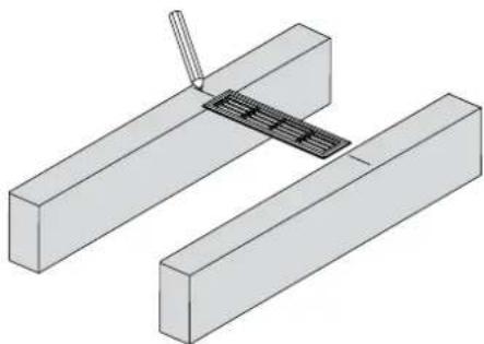
Figure 28
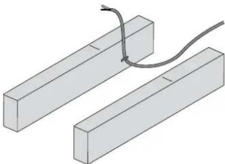
Figure 29
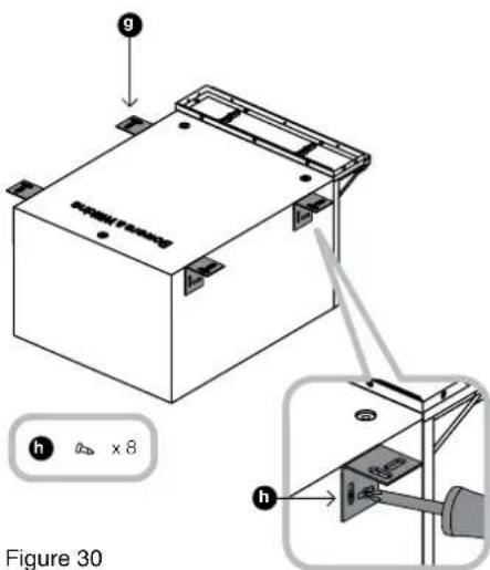
Figure 30
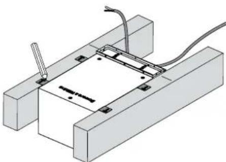
Figure 31

Figure 32 Figure 33
CHIMITE 3aunTHbI CNOyMaHn HANOxNTE
DBe CAMOKJINXHcYIyONTOHTENBHeIpyOKnA
(f),OHy HA ONOpHbI CTpeKHeB, a DpyRyHO-Ha
KOpNcC dpyroT cTOPOHb PAmbI dna JxKaIO3o.
3TN pEZHOBbI PpOKnADKn CnyKaTb dI
BbPON30ANrnnr nncokapTOHHnx naHEne, YTO6bl
npDeToBPaNTb Ix npe6e3r (Figure 34).
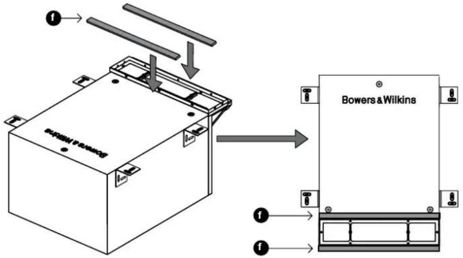
Figure 34
YcTaHOBITE ca6Byfepe no6n30CTNOT
HameeHHoro nnoKoeHHa 3aCmTTE KOHbI
Ka6eJIu COeHNITHe X cPnyKHHbIMn
pa3BeMaMHa KOpNyce,co6JIOaI npI 3OM
NoIAPHOCTb. YtObI neoDpTaPTb Dpe6E3r,
3aKePeINe MluHNI KcHoeu Ka6eJIHa ca6Byfepe
c NMOUBO CTAAKK (Figure 35).
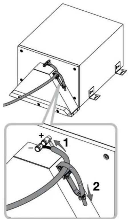
Figure 35
BctabBe cabyep Ha MeTo, TaK Tc06bl Cko6bl nonann B BbEMKn DnH Nx, nPnPKpENMe Tc06bl wypynAm K nepeoropokam (wypynbl dnn 3oTO He npnnaiaOTc) (Figure 36).
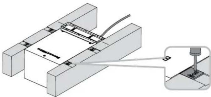
Figure 36
Ecnn Bbl nCnObn3yeTe nIcTOboe nokpbItne
dln nona,ncnO3yte wA6NoH (e) dnnrTOrO,
YtObbl Hametntb KOHTyp npOemaB nOny. 10ctb
BbCTyNob WbA6NoHa COOTBeTCTByIOT BHEuHM
pa3Mepam peWetTK C xAJIO3N cCenahbl
ToBko Dn rTO, YtObbl NOKa3atb Heo6XoDMbIe
ra6apntb. He pa3MeauNe KOnTy pNo 3TNM
BbCTYnAm, aOBBeNTe HcTeK no NyHKtnPHbIM
nHHaM, KOTOpBie nx OTCeKaIOT (Figure 37).
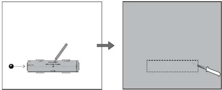
Figure 37
Ha 3TOM 3Tane Bbl MoXeTe HnHeCTn MaKyIO
MACTNY HA NInueByo NOBepxHOCTb KOpNyca
cABbyepa, YTObeI ppeOToBpATNb Dpe6e3r 06
RINCOKAPTOHHIE NaHEn.
JINIOCTOBORO NOKpbTNIPONA, HANOXKNTe ETO TAK, YTO6bI BIIpe3I NpPEWETKN JAAIO3N OKA3NJB R BYHKHOM MceTe.
JN NOKpBnTNOI, COCTOGERN 03 OTENHbIX NONOC, yNtne IN TAK, YTObI OHN BNTHOYU JERNI BOKpy BILCTNYAIOE peWETKN.
Tam rte 30oBzMOxHO (CM. npdynpexdHeHBe H aane 3tOrO pa3de), yNOnKe KOBpHK INnpoeXbTe B HEM OTBepCtnIe IpeWetKn.
Ha 3TOM 3Tane,ecJINXOTNTe,MOKETe BBkpcntb MONDHr peWETKN JAIIO3N.
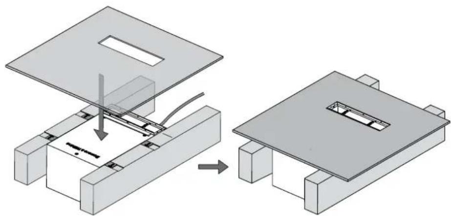
Figure 38
PnuctabTe XaIIO3n (c) CnepeN K npoemy n npkpenTe IN K pAmE C nOmoBb DByx BOnTOB M3 (i) nponyuEnHbX Hepe3 Dee nonepeHbI. He nepetraNBaTe 3Tu BOnTb.Ide nonepeHbI duONKbI cnerKa nporHyTBcR, HO IX OKpyKeHHe He dONXHO NCKpBNbTCBc, INaYe paMka He coBNaTe C XaJIIO3n.
HaJeHbTe XaJIIO3n (b) HaIINuEByIO nAHeNb (c) (Figure 39).
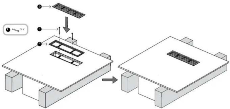
Figure 39
6 YctahOBKa B KkyoHHyIO Tym6y
Ca6byfpepnJKeH Jekatb Ha HmKHei nonke Tym6bI n3nyaTb 3Byk Kepe3 peWetKy noD Dbepeu
CHMNTE 3aunTHbI cnoB yMaHn HANOxNTE OyH N3 CAMOKNHEXCAYNIOHTHEJBhIX npoknaok (f),Ha npoJOnKeHne pactpyBa, BdoNb rpaHpAMKnKanIO3N.
PnKpEnIte npoOnJxHne pAcTpy6a (d) KpaMke XaHIO3H A OCHOBOM KOpNcY, C NMOUbIO 1060TOB No.4 x 10 MM (I), BCTABHeHHbX B 3apaHe npocBepenHbIe OtBePCTy (Figure 40).
Ha mondunire pamkn yke ectb onda npoknlaika, noctabneHHa 3apahe. Ee hynno npkxtb, korda bbl npknpennre TpoDOnKeHne pacTy6a, T.K. Hanpabnaoune OTBepCTHe COBnayT, eCIn He Cxatb ee KaK cNeyET.

Figure 40
Y6eHNTcB,HTO CTONOpHbIe raiKn NOnHOCTbIO 3aEBPHTyB P3ebSy pe3HOBXb HOKE (k) npikpyTHe BCE TPO HxKu B IN Pe3bOBoBe 0TEpBRCTB K Kopnyce ca6byfepa (Figure 41).

HaepHTe OTMeTky Ha naHemn
noD DEpeue Ha 30 MM (1.2in) HnHexe
noBepXHOHnHEHnEHNoKn. BepxHHa
yactb BpE3a B 3ToHnAneHn He DOnKHa
6bIb HnHexe 3ToHnHm (Figure 42).
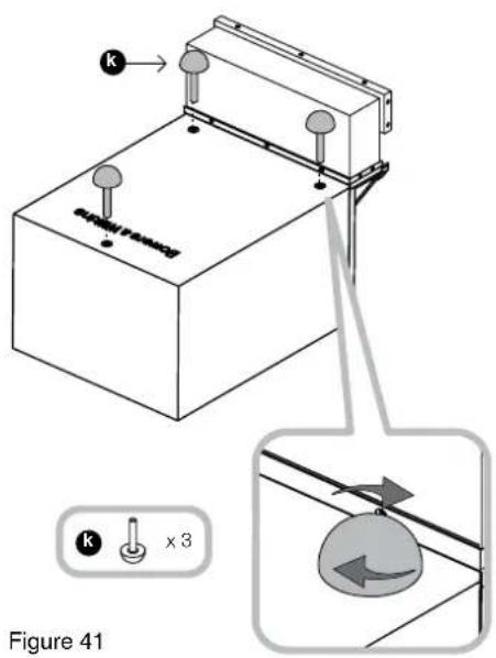
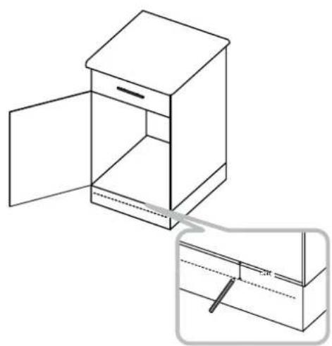
Figure 41
Figure 42

Icnobnb3y npnnaaembIuabNOH, HAMetBe KOHTPOeMaB H NkHNH naHenn, ybeDnBncb, YTO Bepx uabNOHa HAXOITCA HA ODOM YPOBE HNN BIIe HaupeHNoT OTMKn, INTO nepneNkynPnHOCT coBIODeHa.
BbipexBe npoeB hNkne nane n eue Odnn BnHKnHnONKe TmObI, YoOblpa3MeCTnB npoDOnKHepeactpy6. PepeHnra pAhNpoema BnOKe DOnKhA 6bTb 3anoDnloC a3dHn nnockoctbno HNkne naHn (Figure 43).
IpoJNOKInTe KOJIOHOuHbIe Ka6eIM Heo6xOaMOrO CEHeHn DO TOUKN YCTaHOBKn..

Figure 43
YNoKHTe Ca6Bycpep Ha HnKHOIO NOIky,
OTBnHTHtE O6KHN HA HyKHe pACCTORHNE TAK
yTO6bI COBMeCTNb IPODOJKeHNe pACTpyBa c
Bblpe3OM B HnKHe NaHE. OCTaBN B HOKKN
B 3T0M NNOKeHIN, 3aTHHtE KOHTPraIKN
k Ca6Bypepy, YTO6bI 3aDfNKCuPObaTb 3TO
noJONKeHne (Figure 44).
3aHCTNTe KOHbI Ka6EJI N CoeINHnTe IN C npyKHHbIM PA3bEBAMM HA KOpRyCe, COBIOaI npN 3TOM NOIaPHOCTb. TcO6bI npeoTbPAtNTb dpe63E3, 3aKpENrTI NIIuHN KooEH KoeJI c NOMouhIO CTJKK N Ca6Byfepy (Figure 45).
EcnXOTnTe,MOxTe BbIKpaCnTB MoJINH peWetKn XaIIO3N.
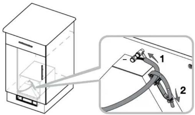
Figure 45
PnctabTe kAnH3n (c) cnepeiK npoeMy nnpkpenTe IN K pAMe C nOmoBdoByb60ntOB M3 (i) (detAb 11) nponyueHBx cheE3 De nonepueHHb. He nepetraHmBa 3tn 60ntb. Da nepeepHHb donKbI cnerKa npOrHytcb, Ho IX OKpyXeHHe NDONKHO NCKPNBtCB, HnAhe pAMKa coBNaTeC kAnH3n.
HaTeKaIO3n (b) HaIeByIO nHeJIb (c) (Figure 46).

Figure 46
7IporpeB npnpa6oTa
3bYaHHe AC cIerka MeHReTcB TceHHe HnAahJbHO rnoPocNoIpaOnuBaHn. EcnI KOHOnKA xpaHInaBc B XoNODHom NOMeUeHHn, TO dIeMnFpyHOuXIN MATEpuaNOB n NOBeCA DnHAMKOB NOTpeSyBCrHEKOTOpoe BPMeHA BOcCTAHOBNEHMe MEXHAnCeCKNX CBOCTB. PIOBec DmΦdyzoparaTke cnerKa CHNkAEET CBOIO XEeCTKOCTB T CEHTeME NEPBbIX cAACOB pAbOtbl. BPMeR, KOTOpOE NotpeSyETCaCBByFepey dIra IONHO BbIXOJa Ha paCtEHbIe xapAKTEpNCTK 3aBMCNT OT yCNOBNx PAHEnHn INHTHCNBHOCTN cNObn3OBAHn. KaNPaBINO, NoTpeSyETc HneDJIHa YcTpaHEnH TMENepATypbIX 3ΦfKeTOB i OKONO 15 cAcob Ha DCIOTNKeHMe MEXAHNeCKMN HACTAMN KeNaEMbIX xapAKTEpNCTK.
VHOrda NoCTyAIOt OT3bIBy, YTO HeO6XoDM Booee dntTeBHyN nePnO npnpa60TK (HaNPmep, MEcRU), ODAHO 3TO, KAK npABINO, He IMeET OTHOWEHK N I MNEHEHNRM B CBOUYTBAX AC, a CKOpee BCERO, CBsAHO C pINBBkaHem CNYATepe K HOBOMY DnI HERO BYUHINIO.
8 yxoa3a ca6ByepoM
Cabbydep 0bHNo He TpeByet HNKaKOrO yXoJa, KpOME NepNOuHeCKOrO CHATN INOHCTKn peSeTKe.
Ecnn cabbypep yctaHOBnEN noI noIOM, cneJeYET nepoIOHNecKn CHIMATb peWetKy XaIO3N IN YnCTNTb NJIeCCOCM pAcTpy6, YTO6bI yDaIHTb MYCOP, KOTOpB MoKeT TAM CKaIIINBaTcR (Figure 35).
Vitejte u Bowers and Wilkins s vyrobkem ISW-3
6 Instalace do kuchynske linky
Suwoofo re obvkyko vklad na dno jedne ze skrnek linky, prcemz vyustje pod jejmi dvinky pres sokl.
Odrante paprov fou lize samolepiho tésnicho pásku (f) a piñepte je na prodlouzeni vyusteni, podel jeho ramečkove hrny.

- Welcome to Bowers & Wilkins and ISW-3
- Contents
- Applications
- Installation in-ceiling
- Installation in-wall
- Installation under the floor
- Installation in a kitchen unit
- Running in
- Aftercare
- Eykarataaon katw ano to dan
- Eykataaon evtoulani kouzivaac
- 2ПуMuEHeHnA
- 3YCTAHOBKaBNOTONOK
- YctahOBKa B CTeHy
- YctaHObKa noq noJOM
- YctahOBKa B KkyoHHyIO Tym6y
- 7IporpeB npnpa6oTa
- yxoa3a ca6ByepoM
- Vitejte u Bowers and Wilkins s vyrobkem ISW-3
- Instalace do kuchynske linky
Brand : BOWERS & WILKINS
Model : ISW3
Category : Subwoofer