
DH 36DBL - Drill HITACHI - Free user manual and instructions
Find the device manual for free DH 36DBL HITACHI in PDF.
| Product type | Cordless rotary hammer |
| Brand | Hitachi |
| Model | DH 36DBL |
| Nominal voltage | 36 V |
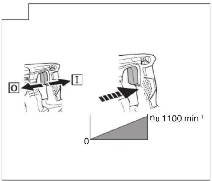
| No-load speed | 0 – 1100 min⁻¹ |
| Full load impact rate | 0 – 4300 min⁻¹ |
| Max. drilling diameter (concrete) | 28 mm |
| Max. drilling diameter (steel) | 20 mm |
| Max. drilling diameter (wood) | 13 mm |
| Max. screw diameter (wood screw) | 32 mm |
| Weight (according to EPTA 01/2003) | 4.8 kg |
| Battery type | Lithium-ion |
| Compatible charger | UC36YSL |
| Charging time (6.0 Ah battery) | Approx. 60 min |
| Operating modes | Rotation + hammer, rotation only, hammer only |
| Direction of rotation | Clockwise and counterclockwise |
| Tool holder | SDS-plus |
| Features | Reactive force control (RFC), LED light, battery charge indicator |
| Sound power level (LWA) | 104 dB(A) |
| Sound pressure level (LpA) | 93 dB(A) |
| Vibrations (drilling in concrete) | 16.0 m/s² (emission value) |
| Standard accessories | Side handle, depth stop, key, case, etc. |
| Maintenance | Regularly clean the ventilation slots and battery compartment |
| Warranty | According to national regulations |
Frequently Asked Questions - DH 36DBL HITACHI
User questions about DH 36DBL HITACHI
0 question about this device. Answer the ones you know or ask your own.
Ask a new question about this device
Download the instructions for your Drill in PDF format for free! Find your manual DH 36DBL - HITACHI and take your electronic device back in hand. On this page are published all the documents necessary for the use of your device. DH 36DBL by HITACHI.
USER MANUAL DH 36DBL HITACHI
natural_image
Line drawing of a Hitachi drill bit with threaded shaft and handle (no text or symbols)DH36DBL

en Handling instructions
de Bedienungsanleitung
fr Mode d'emploi
it Istruzioni per l'uso
nl Gebruiksaanwijzing
es Instrucciones de manejo
pt Instruções de uso
sv Bruksanvisning
da Brugsanvisning
no Bruksanvisning
fi Käyttöohjeet
el Οδηγίες χειρισμού
pl Instrukcja obsługi
hu Kezelési utasítás
cs Návod k obsluze
tr Kullanım talimatları
ro Instructiuni de utilizare
sl Navodila za rokovanje
sk Pokyny na manipuláciu
bg Инструкция за експлоатация
sr Uputstvo za rukovanje
hr Upute za rukovanje
UK Інструкції щодо поводження з пристроєм
ru Инструкция по эксплуатации
GENERAL POWER TOOL SAFETY WARNINGS

WARNING
Read all safety warnings and all instructions.
Failure to follow the warnings and instructions may result in electric shock, fi re and/or serious injury.
Save all warnings and instructions for future reference.
The term “power tool” in the warnings refers to your mains-operated (corded) power tool or battery-operated (cordless) power tool.
1) Work area safety
a) Keep work area clean and well lit. Cluttered or dark areas invite accidents
b) Do not operate power tools in explosive atmospheres, such as in the presence of fl ammable liquids, gases or dust. Power tools create sparks which may ignite the dust or fumes.
c) Keep children and bystanders away while operating a power tool. Distractions can cause you to lose control.
2) Electrical safety
a) Power tool plugs must match the outlet.
Never modify the plug in any way.
Do not use any adapter plugs with earthed (grounded) power tools.
Unmodified plugs and matching outlets will reduce risk of electric shock.
b) Avoid body contact with earthed or grounded surfaces, such as pipes, radiators, ranges and refrigerators. There is an increased risk of electric shock if your body is earthed or grounded.
c) Do not expose power tools to rain or wet conditions. Water entering a power tool will increase the risk of electric shock.
d) Do not abuse the cord. Never use the cord for carrying, pulling or unplugging the power tool. Keep cord away from heat, oil, sharp edges or moving parts.
Damaged or entangled cords increase the risk of electric shock.
e) When operating a power tool outdoors, use an extension cord suitable for outdoor use. Use of a cord suitable for outdoor use reduces the risk of electric shock.
f) If operating a power tool in a damp location is unavoidable, use a residual current device (RCD) protected supply. Use of an RCD reduces the risk of electric shock.
3) Personal safety
a) Stay alert, watch what you are doing and use common sense when operating a power tool. Do not use a power tool while you are tired or under the influence of drugs, alcohol or medication.
A moment of inattention while operating power tools may result in serious personal injury.
b) Use personal protective equipment. Always wear eye protection.
Protective equipment such as dust mask, non-skid safety shoes, hard hat, or hearing protection used for appropriate conditions will reduce personal injuries.
c) Prevent unintentional starting. Ensure the switch is in the off position before connecting to
power source and/or battery pack, picking up or carrying the tool.
Carrying power tools with your fi nger on the switch or energising power tools that have the switch on invites accidents.
d) Remove any adjusting key or wrench before turning the power tool on.
A wrench or a key left attached to a rotating part of the power tool may result in personal injury.
e) Do not overreach. Keep proper footing and balance at all times.
This enables better control of the power tool in unexpected situations.
f) Dress properly. Do not wear loose clothing or jewellery. Keep your hair, clothing and gloves away from moving parts.
Loose clothes, jewellery or long hair can be caught in moving parts.
g) If devices are provided for the connection of dust extraction and collection facilities, ensure these are connected and properly used.
Use of dust collection can reduce dust-related hazards.
4) Power tool use and care
a) Do not force the power tool. Use the correct power tool for your application.
The correct power tool will do the job better and safer at the rate for which it was designed.
b) Do not use the power tool if the switch does not turn it on and off.
Any power tool that cannot be controlled with the switch is dangerous and must be repaired.
c) Disconnect the plug from the power source and/or the battery pack from the power tool before making any adjustments, changing accessories, or storing power tools.
Such preventive safety measures reduce the risk of starting the power tool accidentally.
d) Store idle power tools out of the reach of children and do not allow persons unfamiliar with the power tool or these instructions to operate the power tool.
Power tools are dangerous in the hands of untrained users.
e) Maintain power tools. Check for misalignment or binding of moving parts, breakage of parts and any other condition that may affect the power tool's operation.
If damaged, have the power tool repaired before use.
Many accidents are caused by poorly maintained power tools.
f) Keep cutting tools sharp and clean.
Properly maintained cutting tools with sharp cutting edges are less likely to bind and are easier to control.
g) Use the power tool, accessories and tool bits etc. in accordance with these instructions, taking into account the working conditions and the work to be performed.
Use of the power tool for operations different from those intended could result in a hazardous situation.
5) Battery tool use and care
a) Recharge only with the charger specified by the manufacturer.
A charger that is suitable for one type of battery pack may create a risk of fi re when used with another battery pack.
b) Use power tools only with specifically designated battery packs.
Use of any other battery packs may create a risk of injury and fire.
c) When battery pack is not in use, keep it away from other metal objects, like paper clips, coins, keys, nails, screws or other small metal objects, that can make a connection from one terminal to another.
Shorting the battery terminals together may cause burns or a fire.
d) Under abusive conditions, liquid may be ejected from the battery; avoid contact. If contact accidentally occurs, fl ush with water. If liquid contacts eyes, additionally seek medical help.
Liquid ejected from the battery may cause irritation or burns.
6) Service
a) Have your power tool serviced by a qualified repair person using only identical replacement parts.
This will ensure that the safety of the power tool is maintained.
PRECAUTION
Keep children and infi rm persons away.
When not in use, tools should be stored out of reach of children and infi rm persons.
CORDLESS ROTARY HAMMER SAFETY WARNINGS
1. Wear ear protectors
Exposure to noise can cause hearing loss.
- Use auxiliary handle(s), if supplied with the tool.
Loss of control can cause personal injury.
- Hold power tool by insulated gripping surfaces, when performing an operation where the cutting accessory may contact hidden wiring.
Cutting accessory contacting a "live" wire may make exposed metal parts of the power tool "live" and could give the operator an electric shock.
ADDITIONAL SAFETY WARNINGS
- Do not allow foreign matter to enter the hole for connecting the rechargeable battery.
- Never disassemble the rechargeable battery and charger.
- Never short-circuit the rechargeable battery. Shortcircuting the battery will cause a great electric current and overheat. It results in burn or damage to the battery.
- Do not dispose of the battery in fire. If the battery is burnt, it may explode.
- When using this unit continuously, the unit may overheat, leading to damage in the motor and switch. Please leave it without using it for approximately 15 minutes.
- Do not insert object into the air ventilation slots of the charger. Inserting metal objects or inflammables into the charger air ventilation slots will result in electrical shock hazard or damaged charger.
- Bring the battery to the shop from which it was purchased as soon as the post-charging battery life becomes too short for practical use. Do not dispose of the exhausted battery.
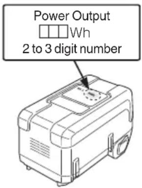
- Before starting to break, chip or drill into a wall, floor or ceiling, thoroughly confi rm that such items as electric cables or conduits are not buried inside.
-
Ensure that the power switch is in the OFF position. If the battery is installed while the power switch is in the ON position, the power tool will start operating immediately, which could cause a serious accident.
-
Do not touch the bit during or immediately after operation. The bit becomes very hot during operation and could cause serious burns.
-
Always hold the body handle and side handle of the power tool firmly. Otherwise the counterforce produced may result in inaccurate and even dangerous operation.
-
Wear a dust mask
Do not inhale the harmful dusts generated in drilling or chiseling operation. The dust can endanger the health of yourself and bystanders.
-
Make sure that the battery is installed firmly. If it is at all loose it could come off and cause an accident.
-
To prevent accidents, make sure to turn the switch off and pull out the battery before changing accessories, storing, carrying or when not using the tools.
-
Mounting the drill bit
To prevent accidents, make sure to turn the switch off and pull out the battery.
When using tools such as bull points, drill bits, etc., make sure to use the genuine parts designated by our company.
○ Clean the shank portion of the drill bit.
○ Check the latching by pulling on the drill bit.
-
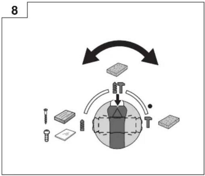
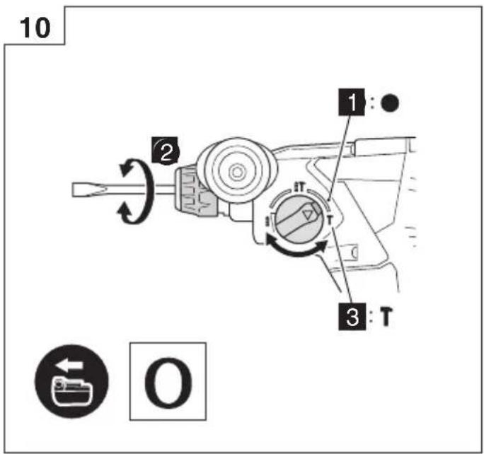
Operate the change lever only when the motor is at a full stop. Operating the change lever while the motor is running may cause the tip tool to unexpectedly rotate and result in an accident. (Fig. 8)
-
Rotation + hammering
DH36DBQL: Using drill bit holder (standard accessories)
DH36DBML: Using drill bit holder (standard accessories)
When the drill bit touches construction iron bar, the bit will stop immediately and the rotary hammer will react to revolve. Therefore firmly tighten the side handle, hold the body handle and side handles.
- Rotation only
To drill wood or metal material using the drill chuck and chuck adapter (optional accessories).
DH36DBQL: Using drill chuck holder (standard accessories)
DH36DBDL: Not using dust extraction unit
DH36DBML: Using drill chuck holder (standard accessories) without dust extraction unit
Application of force more than necessary will not only expedite the work, but will deteriorate the tip edge of the drill bit and reduce the service life of the rotary hammer in addition.
Drill bits may snap off while withdrawing the rotary hammer from the drilled hole. For withdrawing, it is important to use a pushing motion.
○ Do not attempt to drill anchor holes or holes in concrete with the machine set in the rotation only function.
Do not attempt to use the rotary hammer in the rotation and striking mode with the drill chuck and chuck adapter attached. This would seriously shorten the service life of every component of the machine.
- Hammering only
DH36DBQL: Using drill bit holder (standard accessories)
DH36DBDL: Not using dust extraction unit
DH36DBML: Using drill bit holder (standard accessories) without dust extraction
- Do not look directly into the light. Such actions could result in eye injury.
Wipe off any dirt or grime attached to the lens of the LED light with a soft cloth, being careful not to scratch the lens. Scratches on the lens of the LED light can result in decreased brightness.
The LED light will not light up when installing the dust extraction unit.
CAUTION ON LITHIUM-ION BATTERY
To extend the lifetime, the lithium-ion battery equips with the protection function to stop the output.
In the cases of 1 to 3 described below, when using this product, even if you are pulling the switch, the motor may stop. This is not the trouble but the result of protection function.
- When the battery power remaining runs out, the motor stops.
In such a case, charge it up immediately.
-
If the tool is overloaded, the motor may stop. In this case, release the switch of tool and eliminate causes of overloading. After that, you can use it again.
-
If the battery is overheated under overload work, the battery power may stop.
In this case, stop using the battery and let the battery cool. After that, you can use it again.
Furthermore, please heed the following warning and caution.
WARNING
In order to prevent any battery leakage, heat generation, smoke emission, explosion and ignition beforehand, please be sure to heed the following precautions.
- Make sure that swarf and dust do not collect on the battery.
- During work make sure that swarf and dust do not fall on the battery.
○ Make sure that any swarf and dust falling on the power tool during work do not collect on the battery.
○ Do not store an unused battery in a location exposed to swarf and dust.
Before storing a battery, remove any swarf and dust that may adhere to it and do not store it together with metal parts (screws, nails, etc.).
-
Do not pierce battery with a sharp object such as a nail, strike with a hammer, step on, throw or subject the battery to severe physical shock.
-
Do not use an apparently damaged or deformed battery.
-
Do not use the battery in reverse polarity.
-
Do not connect directly to an electrical outlets or car cigarette lighter sockets.
-
Do not use the battery for a purpose other than those specified.
-
If the battery charging fails to complete even when a specified recharging time has elapsed, immediately stop further recharging.
-
Do not put or subject the battery to high temperatures or high pressure such as into a microwave oven, dryer, or high pressure container.
-
Keep away from fi re immediately when leakage or foul odor are detected.
-
Do not use in a location where strong static electricity generates.
-
If there is battery leakage, foul odor, heat generated, discolored or deformed, or in any way appears abnormal during use, recharging or storage, immediately remove it from the equipment or battery charger, and stop use.
CAUTION
- If liquid leaking from the battery gets into your eyes, do not rub your eyes and wash them well with fresh clean water such as tap water and contact a doctor immediately.
If left untreated, the liquid may cause eye-problems.
- If liquid leaks onto your skin or clothes, wash well with clean water such as tap water immediately.
There is a possibility that this can cause skin irritation.
- If you find rust, foul odor, overheating, discolor, deformation, and/or other irregularities when using the battery for the first time, do not use and return it to your supplier or vendor.
WARNING
If a conductive foreign matter enters in the terminal of lithium ion battery, the battery may be shorted, causing fire. When storing the lithium ion battery, obey surely the rules of following contents.
- Do not place conductive debris, nail and wires such as iron wire and copper wire in the storage case.
To prevent shorting from occurring, load the battery in the tool or insert securely the battery cover for storing until the ventilator is not seen.
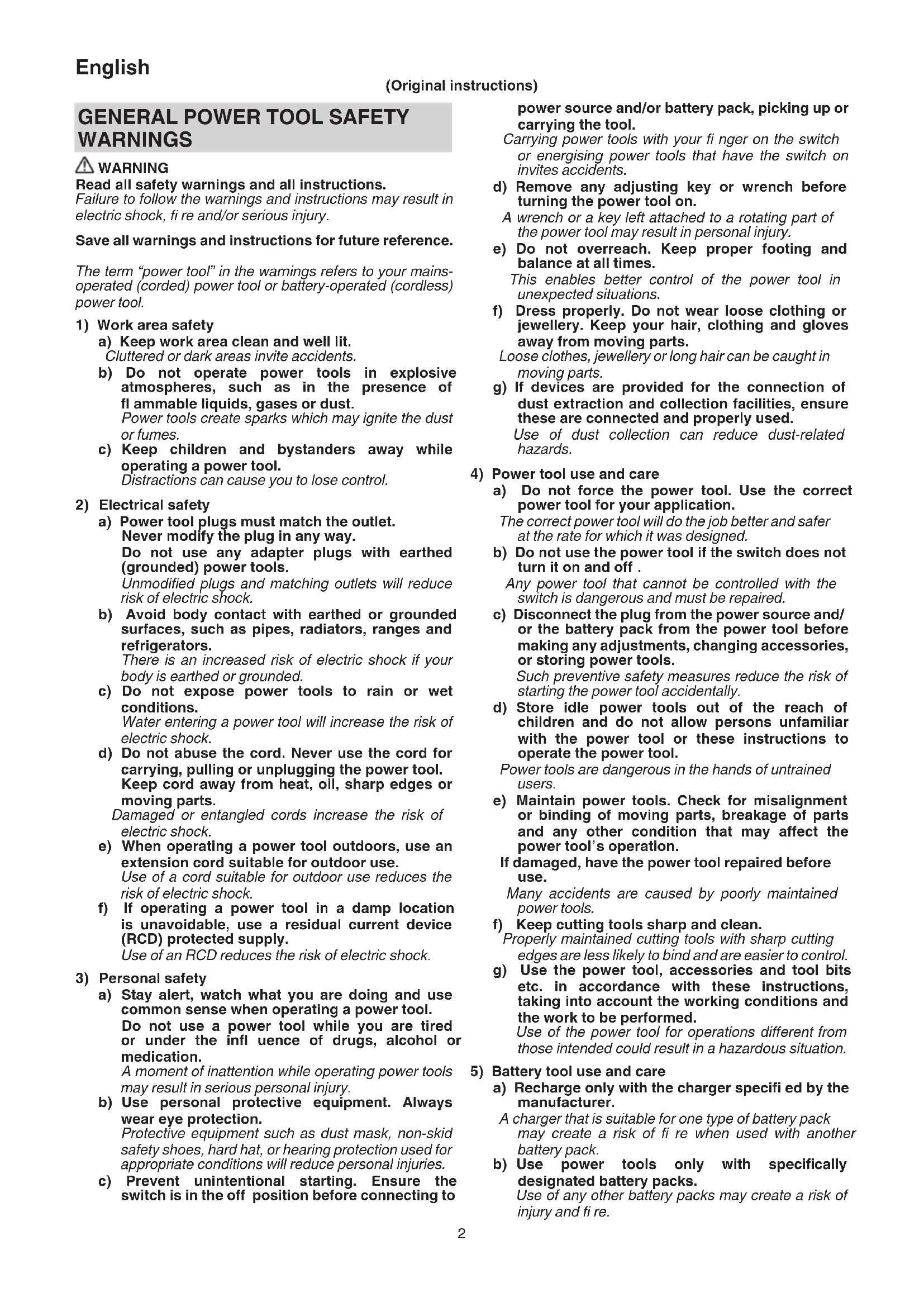
REGARDING LITHIUM-ION BATTERY TRANSPORTATION
When transporting a lithium-ion battery, please observe the following precautions.
WARNING
Notify the transporting company that a package contains a lithium-ion battery, inform the company of its power output and follow the instructions of the transportation company when arranging transport.
○ Lithium-ion batteries that exceed a power output of 100Wh are considered to be in the freight classification of Dangerous Goods and will require special application procedures.
☐ For transportation abroad, you must comply with international law and the rules and regulations of the destination country.
SYMBOLS
WARNING
The following show symbols used for the machine. Be sure that you understand their meaning before use.
| DH36DBL / DH36DBQL / DH36DBDL / DH36DBML: Cordless Rotary Hammer | |
 | To reduce the risk of injury, user must read instruction manual. |
 | Only for EU countriesDo not dispose of electric tools together with household waste material!In observance of European Directive 2002/96/ECon waste electrical and electronic equipment and its implementation in accordance with national law, electric tools that have reached the end of their life must be collected separately and returned to an environmentally compatible recycling facility. |
| V Rated voltage | |
| n_0 | No-load speed |
| Bpm Full-load impact rate | |
| max | Drilling diameter, max. |
| Weight(According to EPTA-Procedure 01/2003) | |
| Concrete | |
| Steel | |
| Wood | |
| Wood screw | |
| Hammering only function | |
| Rotation only function | |
| Rotation and hammering function | |
| Switching ON | |
| Switching OFF | |
| Disconnect the battery | |
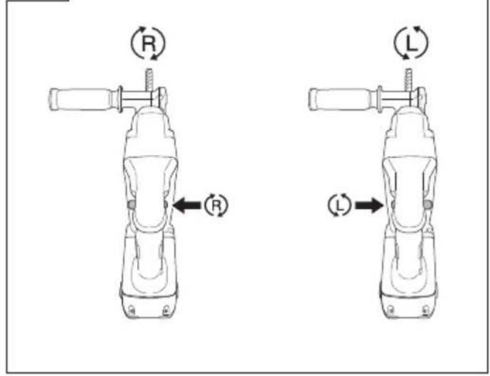
| Clockwise rotation | |
| Counterclockwise rotation | |
| Remaining battery indicator switch | |
| The battery remaining power is nearly empty.Recharge the battery soonest possible | |
| The battery remaining power is a half. | |
| The battery remaining power is enough. | |
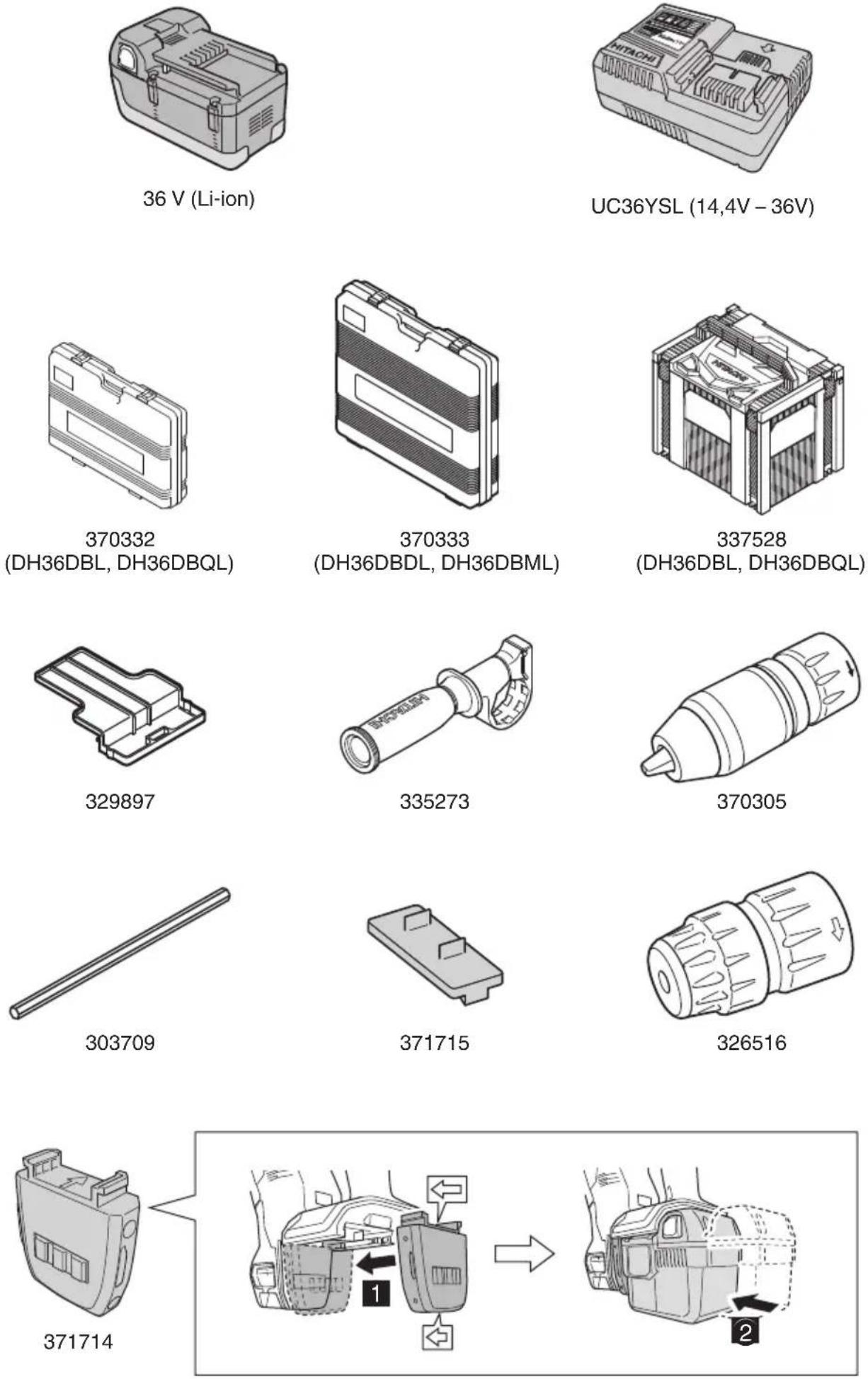
STANDARD ACCESSORIES
In addition to the main unit (1 unit), the package contains the accessories listed on page 184.
Standard accessories are subject to change without notice.
APPLICATIONS
Rotation and hammering function IT
○ Drilling anchor holes
○ Drilling holes in concrete
○ Drilling holes in tile
Rotation only function (without dust extraction unit)
○ Drilling in steel or wood (with optional accessor
○ Tightening machine screws, wood screws (with optional accessories)
Hammering only function T (without dust extraction unit)
○ Light-duty chiselling of concrete, groove digging and edging.
SPECIFICATIONS
The specifications of this machine are listed in the Table on page 184.
NOTE
Due to HITACHI's continuing program of research and development, the specifications herein are subject to change without prior notice.
CHARGING
Before using the power tool, charge the battery as follows.
- Connect the charger's power cord to the receptacle.
When connecting the plug of the charger to a receptacle, the charge indicator lamp will blink in red. (At 1-second intervals)
- Insert the battery into the charger.
Firmly insert the battery into the charger as shown in Fig. 2.
- Charging
When inserting a battery in the charger, charging will commence and the charge indicator lamp will light up continuously in blue.
When the battery becomes fully recharged, the charge indicator lamp will light up continuously in green. (See Table 1)
● Charge indicator lamp indication
The indications of the charge indicator lamp will be as shown in Table 1, according to the condition of the charger or the battery.
Table 1
| Indications of the charge indicator lamp | ||||
| Charge indicator lamp (RED / BLUE / GREEN / PURPLE) | Before charging | Blinks (RED) | Lights for 0.5 seconds. Does not light for 0.5 seconds. (off for 0.5 seconds) | Plugged into power source |
| While charging | Lights (BLUE) | Lights continuously | ||
| Charging complete | Lights (GREEN) | Lights continuously(Continuous buzzer sound: about 6 seconds) | ||
| Overheat standby | Blinks (RED) | Lights for 0.3 seconds. Does not light for 0.3 seconds. (off for 0.3 seconds) | Battery overheated.Unable to charge.(Charging will commence when battery cools) | |
| Charging impossible | Flickers (PURPLE) | Lights for 0.1 seconds. Does not light for 0.1 seconds. (off for 0.1 seconds)(Intermittent buzzer sound: about 2 seconds) | Malfunction in the battery or the charger | |
NOTE
When standby for cooling battery, UC36YSL cools the overheated battery by cooling fan.
English
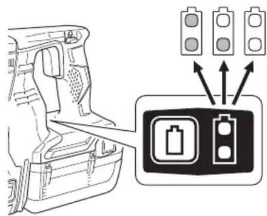
● About the Battery Capacity Lamp
The charge capacity of a battery that is charging can be checked using the battery capacity indicator lamp.
The lamp's indications for the battery capacity are as shown in Table 2.
NOTE
A short time after charging is complete, the battery capacity lamp turns off.
Table 2
| State of lamp Battery capacity | ||
 | Blinks | Battery capacity at less than 25% |
 | Blinks | Battery capacity at less than 50% |
 | Blinks | Battery capacity at less than 75% |
 | Blinks | Battery capacity at more than 75% |
 | Lights | Charging complete |
● Regarding the temperature and charging time of the battery.
The temperatures and charging time will become as shown in the Table 3.
Table 3
| Battery\Charger | UC36YSL | ||||
| Charging voltage V 14.4V 18V 25.2V 36V | |||||
| Type of battery Li-ion | |||||
| Temperatures at which the battery can be recharged | -10°C - 50°C | ||||
| Charging time for battery capacity, approx. (At 20°C) | |||||
| 1.3 Ah | min. | 15 (4 cells) | 15 (5 cells) | - | - |
| 1.5 Ah | min. | 15 (4 cells) | 15 (5 cells) | - | - |
| 2.0 Ah | min. | 20 (4 cells) | 20 (5 cells) | 20 (7 cells) | 20 (10 cells) |
| 2.5 Ah | min. | 25 (4 cells) | 25 (5 cells) | - | 25 (10 cells) |
| 2.6 Ah | min. | - | - | - | 25 (20 cells) |
| 3.0 Ah | min. | 30 (8 cells) | 30 (10 cells) | 30 (14 cells) | - |
| 4.0 Ah | min. | 40 (8 cells) | 40 (10 cells) | - | - |
| 5.0 Ah | min. | 50 (8 cells) | 50 (10 cells) | - | - |
| 6.0 Ah | min. | 60 (8 cells) | 60 (10 cells) | - | 60 (20 cells) |
NOTE
The charging time may vary according to temperature and power source voltage.
CAUTION
When the battery charger has been continuously used, the battery charger will be heated, thus constituting the cause of the failures. Once the charging has been completed, give 15 minutes rest until the next charging.
4. Disconnect the charger's power cord from the receptacle.
5. Hold the charger firmly and pull out the battery.
NOTE
Be sure to pull out the battery from the charger after use, and then keep it.
CAUTION
☐ If the battery is charged while it is heated because it has been left for a long time in a location subject to direct sunlight or because the battery has just been used, the charge indicator lamp of the charger lights for 1 second, does not light for 0.5 seconds (off for 0.5 seconds). In such a case, first let the battery cool, then start charging.
When the charge indicator lamp flickers (at 0.2-second intervals), check for and take out any foreign objects in the charger's battery connector. If there are no foreign objects, it is probable that the battery or charger is malfunctioning. Take it to your authorized Service Center.
○ Since the built-in micro computer takes about 3 seconds to confi rm that the battery being charged with charger is taken out, wait for a minimum of 3 seconds before reinserting it to continue charging. If the battery is reinserted within 3 seconds, the battery may not be properly charged.
MOUNTING AND OPERATION
| Action Figure Page | ||
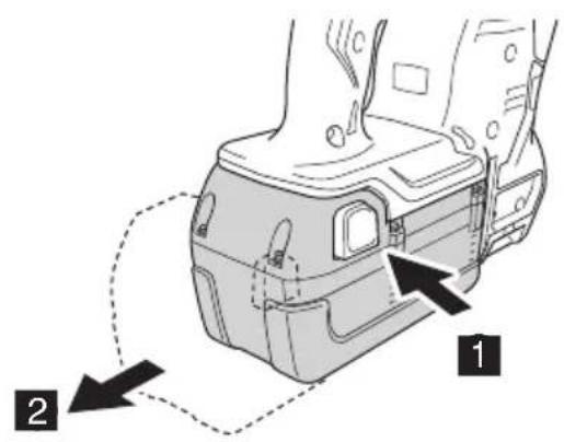
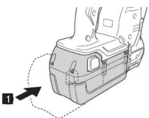
| Removing and inserting the battery | 1 185 | |
| Charging 2 185 | ||
| Remaining battery indicator 3 185 | ||
| Installing / Removing the side handle | 4 185 | |
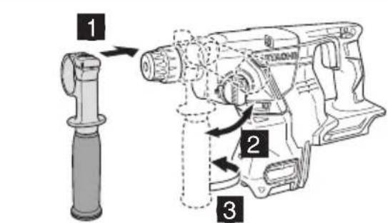
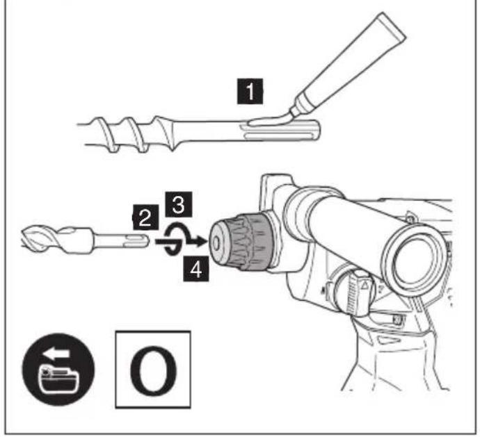
| Inserting SDS-plus drilling tools 5 186 | ||
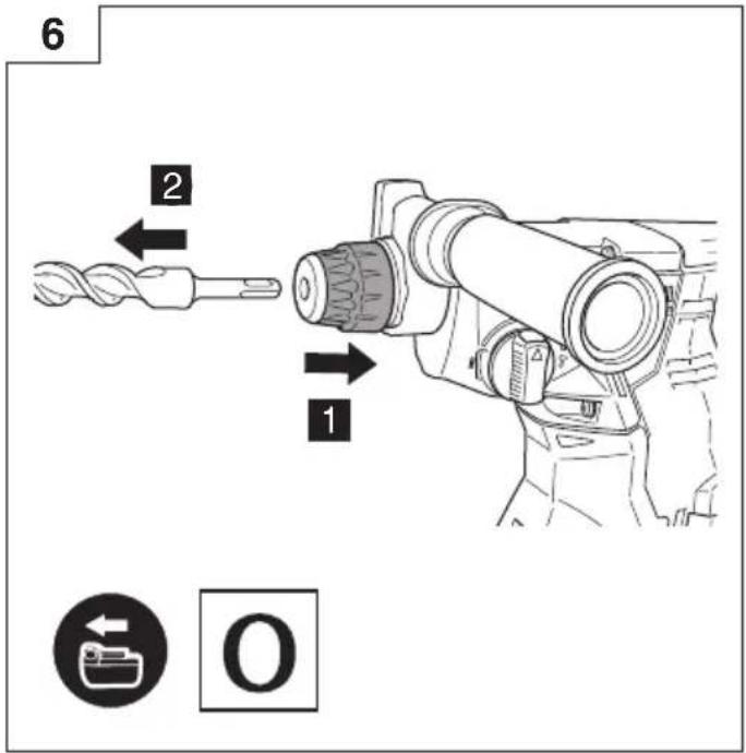
| Removing SDS-plus drilling tools 6 186 | ||
| Selecting rotation direction 7 186 | ||
| Selecting the operating mode 8 186 | ||
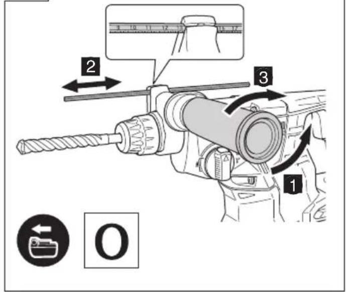
| Adjusting the drilling depth 9 186 | ||
| Changing the chisel position 10 186 | ||
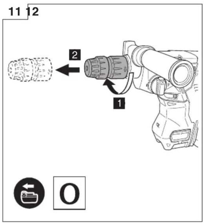
| Removing drill bit holder (DH36DBQL, DH36DBML)*1 | 11 187 | |
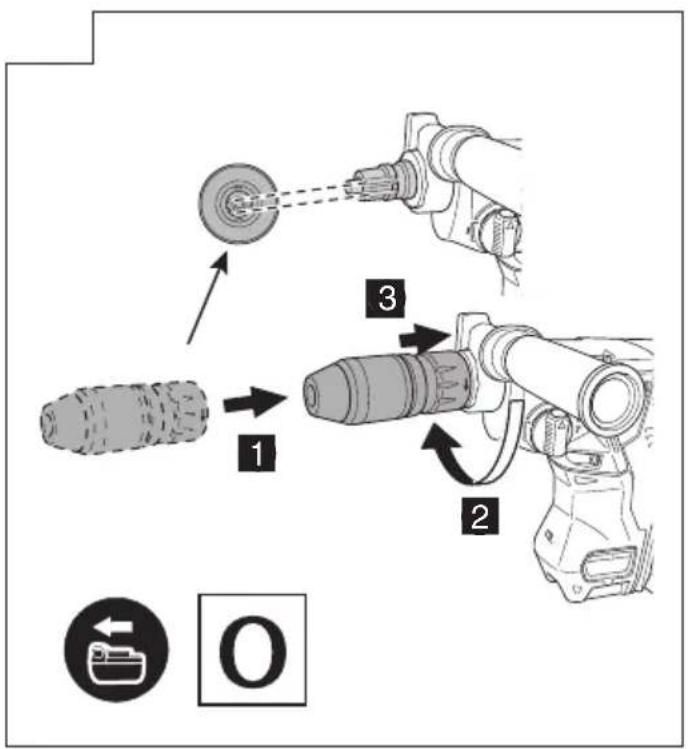
| Inserting drill chuck holder (DH36DBQL, DH36DBML) | 12 187 | |
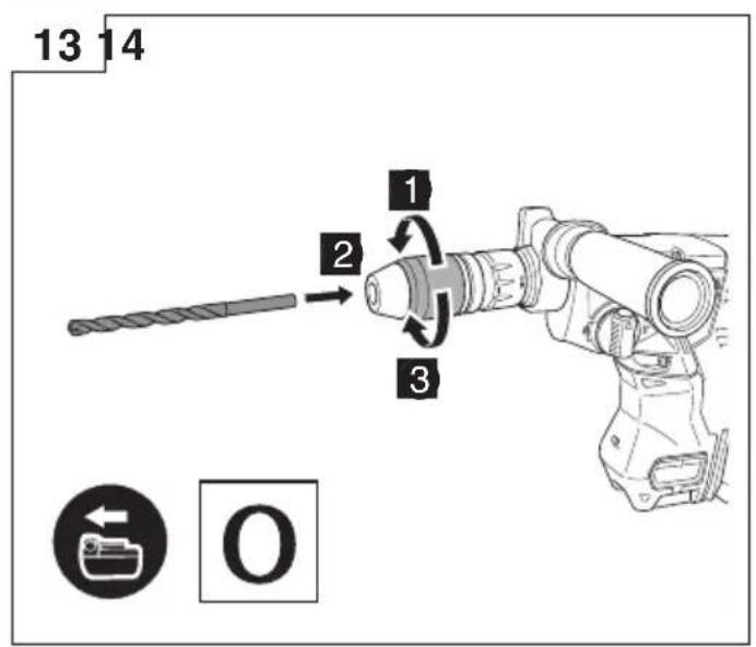
| Inserting round shank applications tools (DH36DBQL, DH36DBML) | 13 187 | |
| Switch operation 14 187 | ||
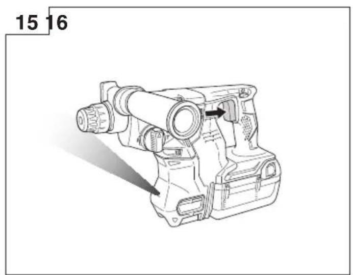
| How to use the LED light 15 187 | ||
| Cleaning of the battery installation compartment | 16 187 | |
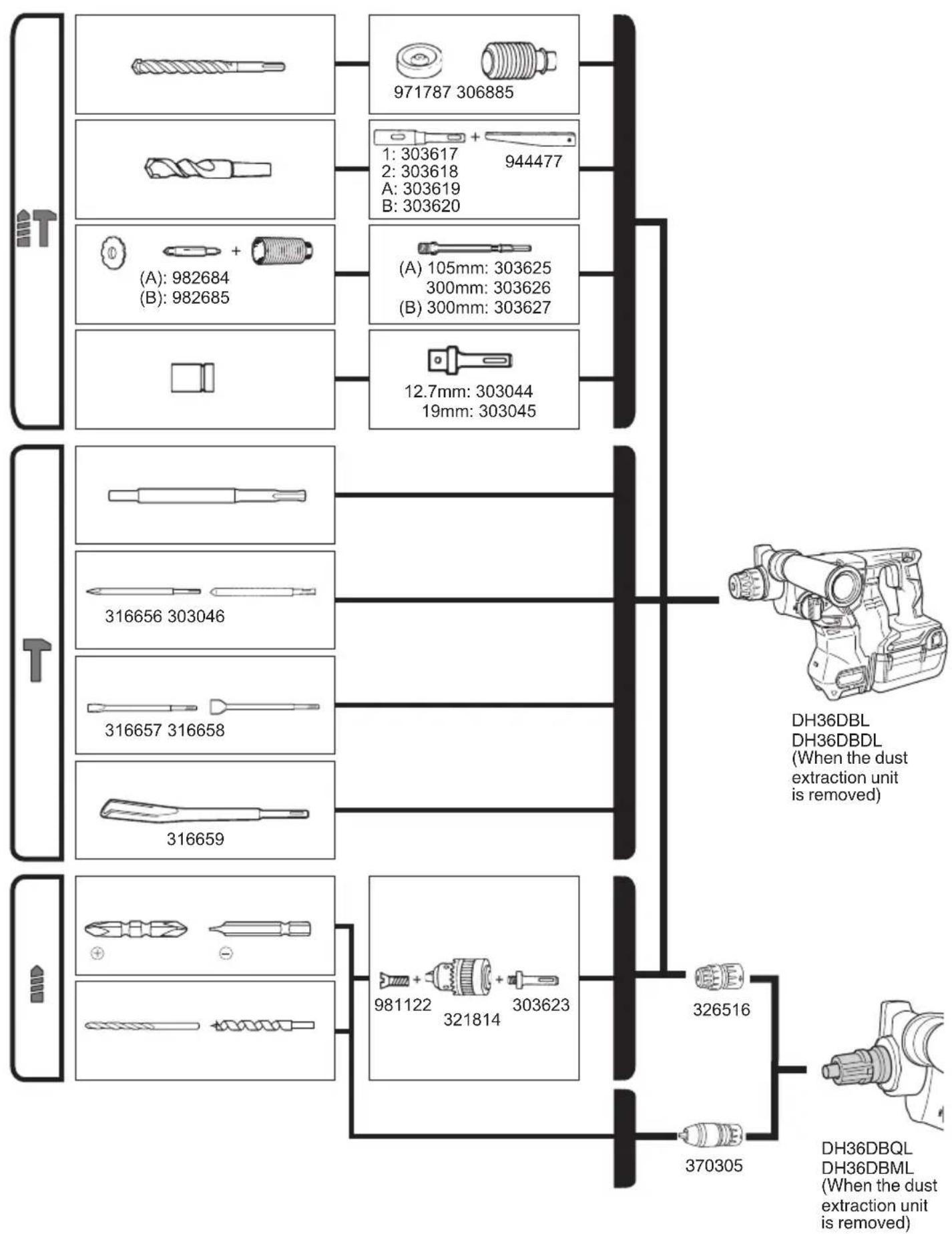
| Selecting accessories — | 188, 189 |
*1 If it is hard to pull out the drill chuck holder or the drill bit holder, align the change lever with the ↑ mark and turn the lock grip.
For details on how to use the dust extraction unit, refer to the separate instruction manual included with this tool. (DH36DBDL/DH36DBML)
REACTIVE FORCE CONTROL
This product is equipped with a Reactive Force Control (RFC) feature that reduces jerking of the tool body.
If the tool bit is suddenly overburdened, any jerking of the tool body is reduced by activation of the slip clutch or by stopping of the motor by the sensor built into the tool body. If the motor is stopped because of overburdening detection by the controller, this is indicated by blinking of the remaining battery lamp while the switch is pulled. (Fig. 17)
Because the RFC feature may not activate or its performance may be insufficient depending on the working environment and conditions, be careful not to suddenly overburden the tool bit while operating.
● Possible causes of sudden overburdening
① Tool bit biting into material
② Impact against nails, metal or other hard objects
③ Tasks involving prying or any excess application of pressure, etc.
Also, other causes include any combination of the aforementioned.
- When the reactive force control (RFC) is triggered. When the RFC is triggered and the motor stops, turn off the tool's switch and remove the cause of the overburdening before continuing operation.
Fig. 17
LUBRICATION
Low viscosity grease is applied to this rotary hammer so that it can be used for a long period without replacing the grease. Please contact the nearest service center for grease replacement when any grease is leaking form loosened screw.
Further use of the rotary hammer despite the grease shortage causes damage to reduce the service life.
CAUTION
A specific grease is used with this machine, therefore, the normal performance of the machine may be badly affected by use of different grease. Please be sure to let one of our service centers to undertake replacement of the grease.
MAINTENANCE AND INSPECTION
CAUTION
Be sure to turned off the switch and remove the battery before maintenance and inspection.
1. Inspecting the tool
Since use of as dull tool will degrade efficiency and cause possible motor malfunction, sharpen or replace the tool as soon as abrasion is noted.
2. Inspecting the mounting screws
Regularly inspect all mounting screws and ensure that they are properly tightened. Should any of the screws be loose, retighten them immediately. Failure to do so could result in serious hazard.
3. Maintenance of the motor
The motor unit winding is the very "heart" of the power tool. Exercise due care to ensure the winding does not become damaged and/or wet with oil or water.
4. Cleaning on the outside
When the power tool is stained, wipe with a soft dry cloth or a cloth moistened with soapy water. Do not use chloric solvents, gasoline or paint thinner, for they melt plastics.
5. Cleaning of the battery installation compartment After drilling concrete, if concrete dust has accumulated on the terminals or the area where the battery slides within the battery installation compartment, clean off the accumulated concrete dust with a dry cloth before using the tool. (Fig. 16)
Also, after cleaning, ensure that the battery can be installed and removed smoothly from the tool.
CAUTION
Using the tool when the battery is covered with concrete dust may lead to accidents such as the battery falling during use.
Furthermore, such use may cause a malfunction or contact failure between the battery and the terminals.
6. Storage
Store the power tool in a place in which the temperature is less than 40^ C and out of reach of children.
English
NOTE
Storing lithium-ion batteries.
Make sure the lithium-ion batteries have been fully charged before storing them.
Prolonged storage (3 months or more) of batteries with a low charge may result in performance deterioration, signifi cantly reducing battery usage time or rendering the batteries incapable of holding a charge.
However, signifi cantly reduced battery usage time may be recovered by repeatedly charging and using the batteries two to five times.
If the battery usage time is extremely short despite repeated charging and use, consider the batteries dead and purchase new batteries.
CAUTION
In the operation and maintenance of power tools, the safety regulations and standards prescribed in each country must be observed.
Important notice on the batteries for the Hitachi cordless power tools
Please always use one of our designated genuine batteries. We cannot guarantee the safety and performance of our cordless power tool when used with batteries other than these designated by us, or when the battery is disassembled and modified (such as disassembly and replacement of cells or other internal parts).
GUARANTEE
We guarantee Hitachi Power Tools in accordance with statutory/country specific regulation. This guarantee does not cover defects or damage due to misuse, abuse, or normal wear and tear. In case of complaint, please send the Power Tool, undismantled, with the GUARANTEE CERTIFICATE found at the end of this Handling instruction, to a Hitachi Authorized Service Center.
Information concerning airborne noise and vibration
The measured values were determined according to EN60745 and declared in accordance with ISO 4871.
Measured A-weighted sound power level:
Measured A-weighted sound pressure level:
93 dB (A) (DH36DBL)
Uncertainty K: 3 dB (A).
Wear hearing protection.
Vibration total values (triax vector sum) determined according to EN60745.
Hammer drilling into concrete:
Vibration emission value a_h , HD = 16.0 m/s² (DH36DBL)
17.0 m/s² (DH36DBQL)
16.5 m/s² (DH36DBDL)
16.0 m/s² (DH36DBML)
Uncertainty K = 1.5 m/s ^4
Equivalent chiselling value:
Vibration emission value a_h , CHeq =
12.2 m/s² (DH36DBL)
11.6 m/s² (DH36DBQL)
Uncertainty K = 1.5 m/s ^4
The declared vibration total value has been measured in accordance with a standard test method and may be used for comparing one tool with another.
It may also be used in a preliminary assessment of exposure.
WARNING
☐ The vibration emission during actual use of the power tool can differ from the declared total value depending in the ways in which the tool is used.
- Identify safety measures to protect the operator that are based on an estimation of exposure in the actual conditions of use (taking account of all parts of the operating cycle such as the times when the tool is switched off and when it is running idle in addition to the trigger time).
NOTE
Due to HITACHI's continuing program of research and development, the specifications herein are subject to change without prior notice.
ALLGEMEINE
Abb. 17
SCHMIERUNG
● Causes possibles de surcharge soudaine
Fig. 17
GRAISSAGE
Fig. 17
LUBRIFICAZIONE
VEILIGHEIDSWAARSCHUWINGEN
Afb. 17
SMEREN
natural_image
Line drawing of a mechanical device with a circular component and a pointer (no text or symbols)SÍMBOLOS
ADVERTENCIA
Fig. 17
LUBRICACION
Fig. 17
LUBRIFICAÇÃO
Bild 17
SMÖRJNING
STYRING AF REAKTIONSKRAFT
Fig. 17
SM∅RING
Fig. 17
SM∅RING
VEDLIKEHOLD OG INSPEKSJON
FORSIKTIG
Kuva 17
VOITELU
Eik. 17
ΛΙΠΑΝΣΗ
Rys. 17
SMAROWANIE
- ábra
KENÉS
obr. 17
MAZÁNÍ
Şekil 17
YAĞLAMA
Fig. 17
LUBRIFIERE
SI. 17
MAZANJE
Obr. 17
MAZANIE
Фиг. 17
CMA3BAHE
Sl. 17
PODMAZIVANJE
Mast sa niskom viskozom se primenjuje na ovaj rotacioni čekić tako da može da se koristi za duži vremenski period bez zamene masti. Molimo kontaktirajte najbliži servisni centar za zamenu maziva kada bilo koje mazivo curi iz olabavljenog šrafa.
Dalje korišćenje rotacionog čekića uprkos nedostatku maziva izaziva oštećenje koje smanjuje radni vek.
OPREZ
Specifično mazivo se koristi kod ove mašine, stoga, na normalan učinak mašine može loše da utiče korišćenje drugačijeg maziva. Molimo da se postarate da jedan od naših servisnih centara preduzme zamenu maziva.
ODRŽAVANJE I PROVERA
OPREZ
Slika 17
PODMAZIVANJE
Mast niske viskoznosti se primjenjuje na rotirajućem čekiću, tako da se može koristiti duže vrijeme bez zamjene masti. Molimo obratite se najbližem servisnom centru za zamjenu maziva kada mazivo curi iz labavih vijaka.
Мал. 17
ЗМАЩУВАННЯ
Рис. 17
CMA3KA
*1 Specifications are for when a dust extraction unit has been installed.
When used with the dust extraction unit uninstalled, the specifications are the same as those for DH36DBL.
*2 Specifications are for when a dust extraction unit has been installed.
When used with the dust extraction unit uninstalled, the specifications are the same as those for DH36DBQL.
natural_image
Technical line drawing of a Hitachi drill bit with base mount (no text or symbols)1
natural_image
Technical diagram of a mechanical component with an arrow indicating a step, no text or symbols present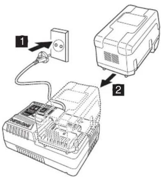
2
3
4


5
7
flowchart
graph TD
    A["Tool"] --> B["Central Component"]
    B --> C["Arrow to Top"]
    B --> D["Arrow to Bottom"]
    B --> E["Arrow to Left"]
    B --> F["Arrow to Right"]
    style B fill:#f9f,stroke:#333,stroke-width:2px
9
natural_image
Technical line drawing of a mechanical device with no visible text or symbols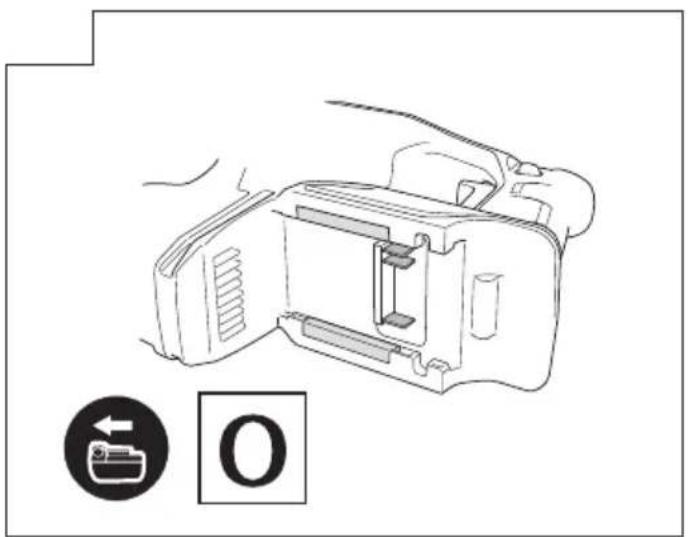
flowchart
graph TD
    A["1: 303617"] --> B["944477"]
    C["2: 303618"] --> B
    D["A: 303619"] --> B
    E["B: 303620"] --> B
    F["(A): 982684"] --> G["+"]
    H["(B): 982685"] --> G
    I["(A): 105mm"] --> J["303625"]
    K["(B): 300mm"] --> L["303626"]
    M["(B): 300mm"] --> L
    N["12.7mm"] --> O["303044"]
    N --> P["19mm"]
    Q["19mm"] --> R["303045"]
    S["316656"] --> T["303046"]
    U["316657"] --> V["316658"]
    W["316659"] --> X["316659"]
    Y["981122"] --> Z["+"]
    AA["321814"] --> AB["+"]
    AC["303623"] --> AD["+"]
    AE["326516"] --> AF["+"]
    AG["370305"] --> AH["+"]
    AI["DH36DBL DH36DBDL (When the dust extraction unit is removed)"]
    AJ["DH36DBQL DH36DBML (When the dust extraction unit is removed)"]

natural_image
Line drawing of a quill pen in an inkwell (no text or symbols)| English Dansk Română | ||||
| GUARANTEE CERTIFICATE1 Model No.2 Serial No.3 Date of Purchase4 Customer Name and Address5 Dealer Name and Address(Please stamp dealer name and address) | GARANTIBEVIS1 Modelnummer2 Serienummer3 Købsdato4 Kundes navn og adresse5 Forhandlers navn og adresse(Indsæt stempel med forhandlers navn og adresse) | CERTIFICAT DE GARANTIE1 Model nr.2 Nr. de serie3 Data cumpărării4 Numele și adresa clientului5 Numele și adresa distribuitorului(Vă rugăm aplicați ștampila cu numele și adresa distribuitorului) | ||
| Deutsch Norsk Slovenščina | ||||
| GARANTIESCHEIN1 Modell-Nr.2 Serien-Nr.3 Kaufdatum4 Name und Anschrift des Kunden5 Name und Anschrift des Händlers(Bitte mit Namen und Anschrift des Handlers abstempeln) | GARANTISERTIFIKAT1 Modellnr.2 Serienr.3 Kjøpsdato4 Kundens navn og adresse5 Forhandlerens navn og adresse(Vennligst stemple forhandlerens navn og adresse) | GARANCIJSKO POTRDILO1 Št. modela2 Serijska št.3 Datum nakupa4 Ime in naslov kupca5 Ime in naslov prodajalca(Prosimo vtsnite žig z imenom in naslovom prodajalca) | ||
| Français Suomi Slovenčina | ||||
| CERTIFICAT DE GARANTIE1 No. de modèle2 No de série3 Date d'achat4 Nom et adresse du client5 Nom et adresse du revendeur(Cachet portant le nom et l'adresse du revendeur) | TAKUUTODISTUS1 Malli nro2 Sarja nro3 Ostopăivămâără4 Asiakkaan nimi ja osoite5 Myyjăn nimi ja osoite(Leimaa myyjăn nimi ja osoite) | ZÁRUČNÝ LISTA1 Č. modelu2 Sériové č.3 Dátum zakúpenia4 Meno a adresa zákaznika5 Názov a adresa predajcu(Pečiatka s názvom a adresou predajcu) | ||
| Italiano Eλληνικά Български | ||||
| CERTIFICATO DI GARANZIA1 Modello2 N° di serie3 Data di acquisto4 Nome e indirizzo dell'acquirente5 Nome e indirizzo del rivenditore(Si prega di apporre il timbro con questi dati) | ПІЗТОПОІНТИКО ЕГГУНЄНЗ1 Ap. Movtėlou2 Aŭξων Ap.3 Нμερομηνία αγοράς4 'Ovoja koi διεύθυνση πελάτη5 'Ovoja kai διεύθυνση μεταπωλητή(Παρακαλούμε να χρησιμοποιηθεί σφραγίδα) | ГАРАНЦИОНЕН СЕРТИФИКАТ1 Модел No2 Сериен No3 Дата за закупуване4 Име и адрес на клиента5 Име и адрес на търговеца(Моля, отпечатайте името и адрес на дильра) | ||
| Nederlands Polski Srpski | ||||
| GARANTIEBEWIJS1 Modelnummer2 Serienummer3 Datum van aankoop4 Naam en adres van de gebruiker5 Naam en adres van de handelaar(Stempel a.u.b. naam en adres vande de handelaar) | GWARANCJA1 Model2 Numer seryjny3 Data zakupu4 Nazwa klienta i adres5 Nazwa dealera i adres(Pieczęć punktu sprzedaży) | GARANTNI SERTIFIKAT1 Br. modela.2 Serijski br.3 Datum kupovine4 Ime i adresa kupca5 Ime i adresa prodavca(Molimo da stavite pečat na ime i adresu trgovca) | ||
| Español Magyar Hrvatski | ||||
| CERTIFICADO DE GARANTÍA1 Número de modelo2 Número de serie3 Fecha de adquisición4 Nombre y dirección del cliente5 Nombre y dirección del distributor(Se ruega poner el sello del distribuidor con su nombre y dirección) | GARANCIA BIZONYLAT1 Tipusszám2 Sorozatszám3 A vásárlás dátuma4 A Vásárló neve és címe5 A Kereskedő neve és címe(Kárjük ide olhelyezni a Kereskedő nevének és címének pecsétjét) | JAMSTVENI CERTIFIKAT1 Br modela.2 Serijski br.3 Datum kupnje4 Ime i adresa kupca5 Ime i adresa trgovca(Molimo stavite pečat na ime i adresu trgovca) | ||
| Português Čeština Український | ||||
| CERTIFICADO DE GARANTIA1 Número do modelo2 Número do série3 Data de compra4 Nome e morada do cliente5 Nome e morada do distribuidor(Por favor, carimbe o nome e morada do distribuidor) | ZÁRUČNÍ LIST1 Model č.2 Série č.3 Datum nákupu4 Jméno a adresa zákazníka5 Jméno a adresa prodejce(Prosíme o razitko se jménem a adresou prodejce) | ГАРАНТИЙНИЙ СЕРТИФИКАТ1 № моделі2 № серії3 Дата придбання4 Im'я і адреса клиента5 Im'я і адреса дилера(Будь ласка, поставте печатку з іменем і адресою дилера) | ||
| Svenska Türkçe | Русский | |||
| GARANTICERTIFIKAT1 Modellnr2 Serienr3 Inköpsdatum4 Kundens namn och adress5 Försäljarens namn och adress(Stámpla försäljarens namn och adress) | GARANTI SERTÍFÍKASI1 Model No.2 Seri No.3 Satin Alma Tarihi4 Müşteri Adı ve Adresi5 Bayi Adı ve Adresi(Lütfen bayi adini ve adresini kaşe olarak basin) | ГАРАНТИЙНЫЙ СЕРТИФИКАТ1 Модель No2 Серийный No3 Дата покупки4 Название и адрес заказчика5 Название и адрес дилера(Пожалуйста, внесите название и адрес дилера) | ||

HITACHI
| 1 | |
| 2 | |
| 3 | |
| 4 | |
| 5 |
Hitachi Power Tools Europe GmbH
Siemensring 34, 47877 Willich, Germany
Tel: +49 2154 49930
Fax: +49 2154 499350
URL: http://www.hitachi-powertools.de
Hitachi Power Tools Netherlands B.V.
Brabanthaven 11, 3433 PJ Nieuwegein, The Netherlands
Tel: +31 30 6084040
Fax: +31 30 6067266
URL: http://www.hitachi-powertools.nl
Hitachi Power Tools (U.K.) Ltd.
Precedent Drive, Rooksley, Milton Keynes, MK 13, 8PJ, U.K.
Tel: +44 1908 660663
Fax: +44 1908 606642
URL: http://www.hitachi-powertools.co.uk
Hitachi Power Tools France S.A.S.
Hitachi Power Tools Belgium N.V./S.A.
Koningin Astridlaan 51, B-1780 Wemmel, Belgium
Tel: +32 2 460 1720
Fax: +32 2 460 2542
URL http://www.hitachi-powertools.be
Hitachi Fercad Power Tools Italia s.p.a
Via Piave 35, 36077, Altavilla Vicentina (VI), Italy
Tel: +39 444 548111
Fax: +39 444 548110
URL: http://www.hitachi-powertools.it
Hitachi Power Tools Iberica, S.A.
C/. Puigbarral, 26-28 Pol. Ind. Can Petit, 08227
TERRASSA(Barcelona), Spain
Tel: +34 93 735 6722
Fax: +34 93 735 7442
URL: http://www.hitachi-powertools.es
Kjeller Vest 7, N-2027 Kjeller, Norway
Tel: (+47) 6692 6600
Fax: (+47) 6692 6650
URL: http://www.hitachi-powertools.no
Hitachi Power Tools Sweden AB
Rotebergsvagen 2B SE-192 78 Sollentuna, Sweden
Tel: (+46) 8 598 999 00
Fax: (+46) 8 598 999 40
URL: http://www.hitachi-powertools.se
Hitachi Power Tools Denmark A/S
Lillebaeltsvej 90, 6715 Esbjerg N, Denmark
Tel: (+45) 75 14 32 00
Fax: (+45) 75 14 36 66
URL: http://www.hitachi-powertools.dk
Hitachi Power Tools Finland Oy
Tupalankatu 9, 15680 Lahti, Finland
Tel: (+358) 20 7431 530
Fax: (+358) 20 7431 531
URL: http://www.hitachi-powertools.fi
Hitachi Power Tools Hungary Kft.
1106 Bogancsvirag U.5-7, Budapest, Hungary
Tel: +36 1 2643433
Fax: +36 1 2643429
URL: http://www.hitachi-powertools.hu
Hitachi Power Tools Polska Sp.z.o.o.
Modricka 205, 664 48 Moravany, Czech, Republic
Tel: +420 547 422 660
Fax: +420 547 213 588
URL: http://www.hitachi-powertools.cz
Hitachi Power Tools RUS L.L.C.
Kashirskoe Shosse 41, bldg. 2, 115409, Moscow, Russia
Tel: +7 495 727 4460
Fax: +7 495 727 4461
URL: http://www.hitachi-pt.ru
Hitachi Power Tools Romania S.R.L.
Ring Road, No. 66, Mustang Traco Warehouses, Warehouse
No.1, Pantelimon City, 077145, Ilfov County, Romania
- GENERAL POWER TOOL SAFETY WARNINGS
- WARNING
- 1) Work area safety
- 2) Electrical safety
- 3) Personal safety
- 4) Power tool use and care
- 5) Battery tool use and care
- 6) Service
- PRECAUTION
- CORDLESS ROTARY HAMMER SAFETY WARNINGS
- Wear ear protectors
- ADDITIONAL SAFETY WARNINGS
- CAUTION ON LITHIUM-ION BATTERY
- CAUTION
- REGARDING LITHIUM-ION BATTERY TRANSPORTATION
- SYMBOLS
- STANDARD ACCESSORIES
- APPLICATIONS
- SPECIFICATIONS
- NOTE
- CHARGING
- English
- ● About the Battery Capacity Lamp
- ● Regarding the temperature and charging time of the battery.
- Disconnect the charger's power cord from the receptacle.
- Hold the charger firmly and pull out the battery.
- REACTIVE FORCE CONTROL
- LUBRICATION
- MAINTENANCE AND INSPECTION
- Inspecting the tool
- Inspecting the mounting screws
- Maintenance of the motor
- Cleaning on the outside
- Cleaning of the battery installation compartment After drilling concrete, if concrete dust has accumulated on the terminals or the area where the battery slides within the battery installation compartment, clean off the accumulated concrete dust with a dry cloth before using the tool. (Fig. 16)
- Storage
- Important notice on the batteries for the Hitachi cordless power tools
- GUARANTEE
- Information concerning airborne noise and vibration
- ALLGEMEINE
- SCHMIERUNG
- GRAISSAGE
- LUBRIFICAZIONE
- VEILIGHEIDSWAARSCHUWINGEN
- SMEREN
- SÍMBOLOS
- ADVERTENCIA
- LUBRICACION
- LUBRIFICAÇÃO
- SMÖRJNING
- STYRING AF REAKTIONSKRAFT
- SM∅RING
- VEDLIKEHOLD OG INSPEKSJON
- FORSIKTIG
- VOITELU
- ΛΙΠΑΝΣΗ
- SMAROWANIE
- KENÉS
- MAZÁNÍ
- YAĞLAMA
- LUBRIFIERE
- MAZANJE
- MAZANIE
- CMA3BAHE
- PODMAZIVANJE
- OPREZ
- ODRŽAVANJE I PROVERA
- ЗМАЩУВАННЯ
- CMA3KA
- HITACHI
- Hitachi Power Tools Europe GmbH
- Hitachi Power Tools Netherlands B.V.
- Hitachi Power Tools (U.K.) Ltd.
- Hitachi Power Tools France S.A.S.
- Hitachi Power Tools Belgium N.V./S.A.
- Hitachi Fercad Power Tools Italia s.p.a
- Hitachi Power Tools Iberica, S.A.
- Hitachi Power Tools Sweden AB
- Hitachi Power Tools Denmark A/S
- Hitachi Power Tools Finland Oy
- Hitachi Power Tools Hungary Kft.
- Hitachi Power Tools Polska Sp.z.o.o.
- Hitachi Power Tools RUS L.L.C.
- Hitachi Power Tools Romania S.R.L.
Brand : HITACHI
Model : DH 36DBL
Category : Drill