PQ18B - Speaker Turbosound - Free user manual and instructions
Find the device manual for free PQ18B Turbosound in PDF.
User questions about PQ18B Turbosound
0 question about this device. Answer the ones you know or ask your own.
Ask a new question about this device
Download the instructions for your Speaker in PDF format for free! Find your manual PQ18B - Turbosound and take your electronic device back in hand. On this page are published all the documents necessary for the use of your device. PQ18B by Turbosound.
USER MANUAL PQ18B Turbosound
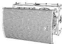
2 Way 10"/12"/15" Full Range Loudspeaker for Tour and Live Sound Applications
PQ18B
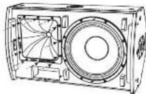
18" Reflex Loaded Subwoofer for Tour and Live Sound Applications
Steel Swivel Bracket for PQ Loudspeakers
PQ10-YB, PQ12-YB, PQ15-YB
Steel Flying Yoke for PQ Loudspeakers
TQ-FB
Fly Bar for PQ_r TQ and MC12-P Series Loudspeakers
SA-35
Stand Adapter for Turbosound Loudspeakers
2PQ Series Quick Start Guide 3
[SA] Safety Instruction
1. Please read and follow all instructions.
2. Keep the apparatus away from water, except for outdoor products.
3. Free only with a dry cough.
4. Do not block any ventilation openings, install in
accordance with the manufacturer's instructions.
5. Proportional mean areal rates such as radiators
beal (r) stess or other aegative including
amplified that produces heat
6. Use only attachment'srciples
the manufacturers

7.Use only specified
cards, stamps, receipts
btractors,or tables,Use
whomoutthe
anaphylaxis combination
-
avoid installing in confined spaces like bookcases.
-
No other place near naked flame sources, such as
lighted candies
- Operating temperature range 5 to 45^
147 in 113T
A
Varning!
Assembly should be carried out by
quilted personnel only, Wrong assembly can lead to personal injury or damage. Screws or other fasteners are not included. Choose screws or fasteners suited to the material in your mounting surface. Make sure your screws and fasteners have sufficient holding power. If you are uncertain, contact your local specialized retailer.
Warning! This appliance has been designed for VERTICAL IMOUNTING ONLY. To avoid potential injury from falling equipment, BD-NTK attempt to mount your speaker cabinet horizontally. The operation of your speaker cabinet as part of a given system, if installed incorrectly and improperly, can potentially cause persons to serious health risks and even death. In addition, please ensure that electrical, mechanical and acoustics considerations are discussed with qualified and efficient (by local, state or national authorities) personnel prior to any installation or flying. Make sure that speaker cabinets are set up and "flow" by qualified and certified personnel only, using dedicated equipment and original parts and components delivered with the unit. If any parts or components are missing please contact your Dealer before attempting to set up the system.
LEGAL DISCLAIMER
Music Tribe accepts no liability for any loss which may be suffered by anyone who relies either wholly or in part upon any description, photograph, or statement contained herein. Technical specifications, appearances and other information are subject to change without notice. All trademarks are the property of their respective owners. Idiosyncratic, Stark Textitk, Lab Gruppo.
Lake, Tarnov, Turbounad, TC Electronic, CT Helkom, Beldinger, Burga, Aston Microplanes and Coolaudio: are trademarks or registered trademarks of Music Title Global Brands Ltd. © Music Title Global Brands Ltd. 2025 All rights reserved.
LIMITED WARRANTY
For the applicable warranty terms and conditions and additional information regarding Music Tribe's Limited Warranty, please see complete details online at community.musictrib.com/support.
unachemical installation process engineering
Xerereans sice hsehns and Oioeale and
8PQ Series Quick Start Guide 9
Welcome
Thank you for choosing a furbsound loudspeaker product for your application. If you would like further information about this or any other product, please visit our website at furbsound.com.
Unpacking the Loudspeaker
After unpacking the unit, please check carefully for damage. If damage is found, please notify your supplier at once. You, the consignee, must instigate any claim. Please retain all packaging in case of future return shipment.
About this Quick Start Guide
This OSG describes details of the PO10, PO12, PO15 loudspeakers and the PO18B subwoofer. The OSG also shows various options such as the TO, FB fly bar, PO-YB yoke bracket, PO-SB swivel bracket, and SA-35 pole mount bracket, in readiness for suspending or pole mounting. These instructions shall only be used with these components.
The optional rigging components [1Q-18 fly bar, PQ-WB yoke bracket, PQ-SB wheel bracket, and SA-15 pole mount bracket] shall only be used in conjunction with Tauruscope PQ loudspeakers as described in this quick start guide.
The instructions do not show details of external lifting equipment and do not contain details of safe lifting procedures or installation.
Possession of these instructions and procedures does not imply authorisation for their use.
General Safety
The operation of your product as part of a suspended system, if installed incorrectly and improperly, can potentially expose persons to serious health risks and even death. In addition, please ensure that electrical, mechanical and acoustic considerations are discussed with qualified and certified (by local, state or national authorities) personnel prior to any installation.
In installation and setup should only be carried out by qualified and authorised personnel observing the valid local, state and other safety regulations applicable in your country. If any parts or components are missing please contact year dealer before attempting to set up the system.
It is the responsibility of the person installing the assembly to ensure that the suspension fixig points are suitable for the intended use.
We also recommend you schedule Turbosound training with our sales partners and applications team.
Equipment used to connect to the Turbrough rigging system must be properly rated and must conform to the local, state and other safety regulations. Do not use Turbrough rigging with other types or brands of loudspeakers. This practice may compromise safety standards and Music Tribe Global Brands Ltd will not be responsible for damage or injury to caused. Do not modify the accessories, or cause them in a way other than that described in this QSG. Rigging components supplied as part of a complete assembly are non-interchangeable and must not be exchanged with the component parts of any other assembly.
Welding, or any other means of permanently fixing rigging components to each other or to cabinet fixing points is not allowed. Rigging components or assemblies must only be fixed to Turbound loudspeaker cabinets using the cabinet fixing paints.
Music Title Global Brands (t) assumes no liability for any damage or personal injury resulting from improper use, installation or operation of the product. Regular checks must be conducted by qualified personnel to ensure that the system remains in a secure and stable condition. Make sure that where the product is suspended, the area undistacted the product is free of human traffic. Do not suspend the product in areas which can be entered or used by members of the public.
Always refer to EASE Focus 3 modeling software error and warning indications prior to installation.
Secondary Safeties
All loudspeakers flown in theater, studios or other places of work and entertainment thal, in addition to the principle load bearing means of suspensor, he provided with an independent, properly rated, and securely attached secondary safety. Only steel wire npes or steel chains of an approved construction and load rating shall be used as secondary safeties. Plastic-covered steel wire npes are not permitted for use as secondary safeties.
The secondary safety suspension must be independent of the primary suspension points and capable of carrying the total system weight. The additional safety device must be mounted in a way that the loudspeaker is caught by the safety device without any drop and swing, in the event that the primary suspension falls.
Operational Safety
The procedures require the use of two or more authorised persons.
Produce a lift plan: before any lift takes place, you must formulate a lift plan that describes the exact steps and procedures that will be carried out.
The plan must be shared with all assistants and stake-holders in the lift so that each person will understand their responsibilities.
Observe all Instructions given on the respective Instruction labels of the rigging components and loudspeakers.
When using chain hosts, make sure nobody is directly undermeech or in the vicinity of the loudspeakers.
During assembly pay attention to the possible risk of crushing.
Wear suitable protective clothing
Safety Inspections
Carefully inspect riging system components and cabinets for defects or signs of damage before proceeding to assemble the speaker to be灵敏. If any parts are damaged or suspect, or if there is any doubt as to the proper functioning and safety of the items DO NOT USE THEM and withdraw them from use immediately.
System Requirements
PQ10, PQ12, and PQ15 full range speakers and the PQ18B subwoofer operate as a passive system and require only one amplifier channel and OSF for normal forward firing operation; Cardboard bass set ups will require additional amplifier and OSF channels.
All P3 series leadspeaker exclusively use Lake pre sets via Lab Gruppen PLM 1 and D series LPs, Lab Gruppen IPX Series pre sets will be released in due time. No 3rd-party amplifier and DSP platforms are supported, no raw pre-set data is revealed or supported.
The PQ series has a powerful yet simple pre-set strategy utilizing the latest functionality of LAKE XP software.
Pre-set data is found either via Lake LOW Library (https://www.libguppen.com/downloads.html) or can be downloaded from https://www.ruboursound.com/downloads.html.
Recommended Lab Gruppen PLM+ models for Touring applications are the PLM8k44, PLM12k44 and PLN20k44.
For Installations using Lab Gruppen D series 1 models, please use lab Gruppen CAPP software - available for download from www.baogruppen.com to determine the optimum amplifier configuration for year system.
System Cabling Requirements
To avoid contacting amplifier power, you should use heavy-duty speaker cable with a minimum wire size of 2.5 mm [14 AWG], and preferably 4 mm [12 AWG] for longer runs or where total cabinet input impedance is less than 8 ohms. For extreme cable lengths, be aware of cable impedance and resistive losses. Always observe the correct polarity.
Use genuine 2x144M Connectors for reliable operation.
Attack and support the speaker cables from your amplifiers to the loudspeaker cabinets, so that no significant additional weight or lateral force is applied to the speakers by the input wiring. Input cables or link cables should never be used to angle the speakers or used as rigging in any way.
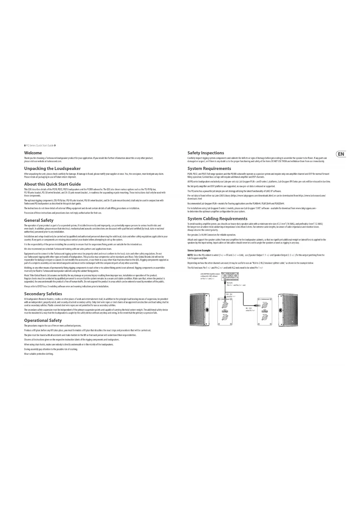
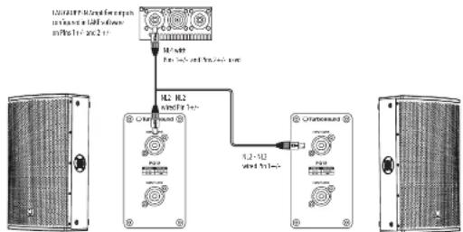
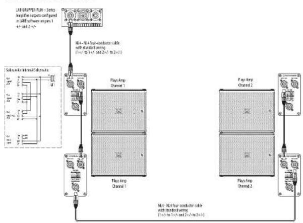
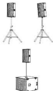
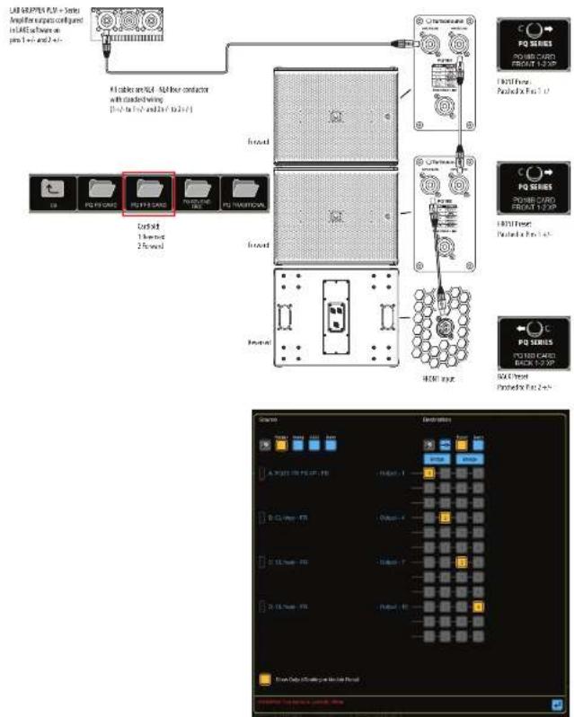
Stereo System Example
NOTE: Since the PO cabinet is wired (1 + i - 2 for 2 + i - 2 = Link) , use [Speaker Output 1: 1 + i - 2 and Speaker Output 2: 2 + i - 2 for the output patching from the Lab Group amplifier
Depending on how the other channels are used, it may be useful to use an "NL 4.0 to NL 2.5 outbreak splitter cable," as shown in the example below. The NL4 and uses Pin 1 + + and Pin 2 + + , and both NL2 ends need to be wired Pin 1 + + .
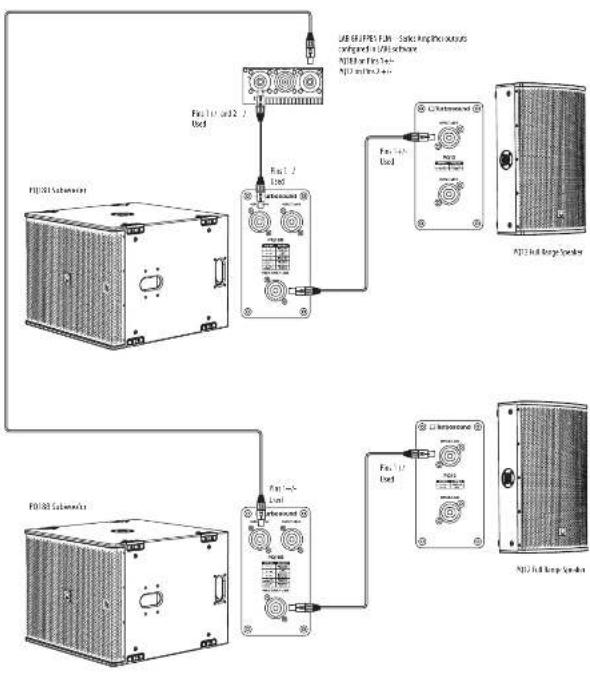
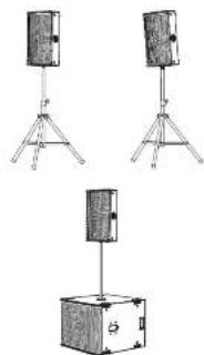
Stereo System Example with PQ18B Subwoofoers
Note: Since the PI cabinet is wired (1 - r = FR and 2 + r = link) , the output pitch can be selected from any of the 4 options [1, 2, 3, 4-2] from the Lab Gropper PI+ amplifier.
This example of a stereo system shows two P012 speakers and two P018B subfooders. The standard RL4 cables to connect the subfoiler's PINS SWAP Link to the INPUT of the P012.
Note: In this case, do not use the PQ188 subwoofer front input, as it uses Pin 2-4 connected to the woofer.
QuickStart
11
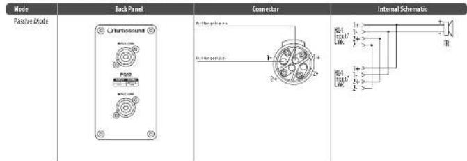
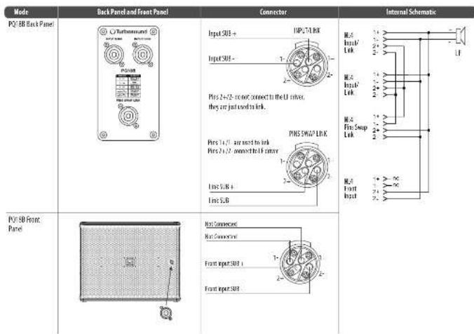
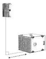
Subwoofer Cabling
NOTE: The P1088 subsoofer is wired 1+/- = 1 and 2+/- = 1INK. The PIN SWAP LINK connector is used in order to power multiple enclosures using standard
NC4Cables
In power nighy pwhopper per amplifor channel, a standard N4 cable from Lab Sponenbi wired N4 amputs (Channe 1 = 1/2- Channe 2 = 3/2) cemtns to the
first subsoer, then another standard kL4 cable is connected via the PIR SWAP link to the INPUT of the second subsoyer.
To power two subwaders per amplifier channel, standard 8.4 low cable from Lab Groupen bi-wired bi outputs (Channel 1 = 1 + ; Channel 2 = 2 + ; can be used in use; refer to wiring diagrams below for further details).
One subwoofer per amplifier channel
Two subwoofoers per amplifier channel
EN
12P0 Seres Quick Stnnd Guide 13
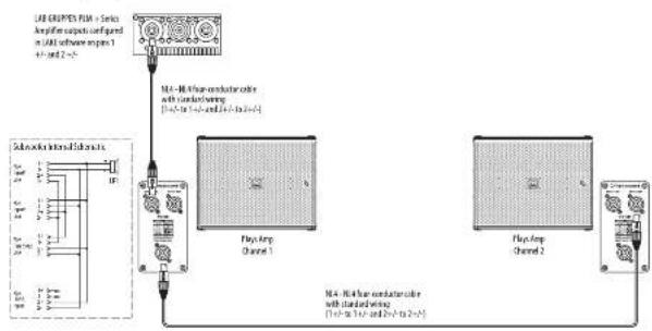
Cardiod BFF (back, forward, forward)
Using 4-Core NL4 cable, 2 DSP and 2 amplifier channels

Connections
Caution: It is mandatory to use the official factory Use pre-set, Failure to do so will result in component failure of the PQ passover crossover and transducers. No other 3rd party DSP or Amplifiers are supported


EN
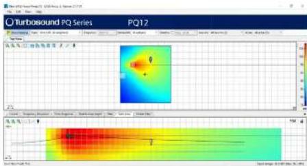
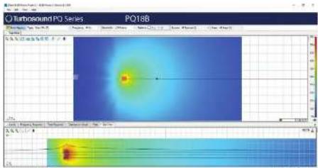
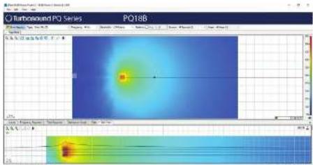
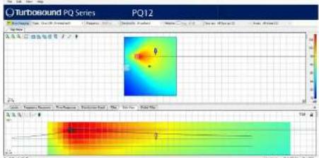
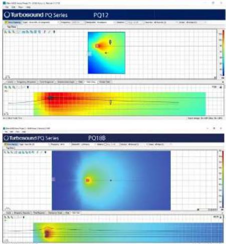
Rigging and Acoustic Simulation Software
The PQ speakers have 1 optional rigging accessories: TG-HB fly bar, PQ-YB yoke bracket, and the PQ-SB swivel bracket. These accessories comply with BCG-C1 rigging standards.
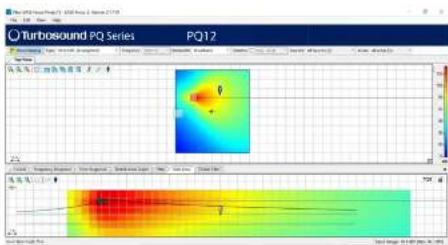
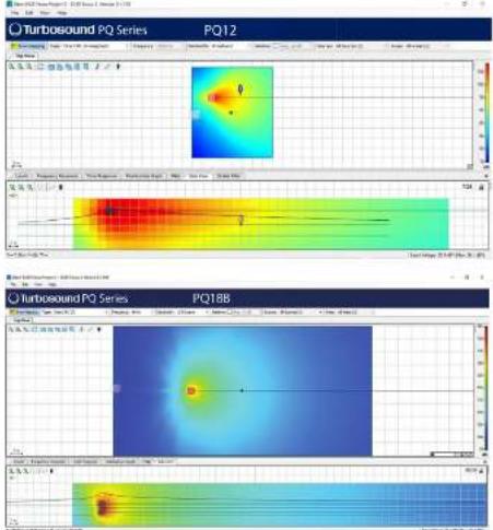
The PO speakers and the PO18B subwoofer are not arrayable products. They are supported in Case Focus 3 in stand-alone use, with Manchester series subwooform, as a fill or delay speaker as part of larger Manchester series systems.
LASF 3x is an acoustic simulation program, available as a free download from https://www.afslng.mri/en/series-focus. The graphs below are typical of LASF 3x data. Use the actual program for exact data for those speakers.

Full EASE data can be downloaded from www.turbosound.com This will allow acoustic prediction, array formation and suspension to be determined. Important safety information about WLL is also calculated by EASE Focus.


Installation PQ10, PQ12, PQ15
Safety Warning: Only authorized and certified personnel shall design and install suspended configurations. Incorrect installation may lead to death or permanent injury.
The use of a secondary safety is a mandatory safety requirement.
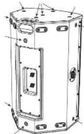
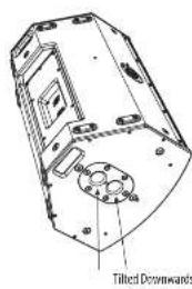
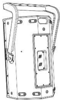
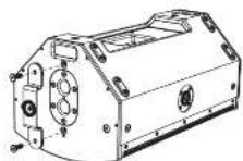
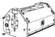
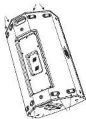
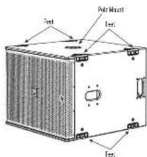
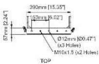
The versatile PQ speaker has two sets of four feet for tilting the speaker as a stage monitor, two integral pole mount holes, and M10 mounting holes with fitted head socket head screws.
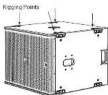
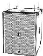
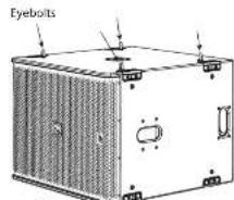
PQ series cabinets are designed with multiple internal rigging points to suit many possible mounting methods in permanent installations. All cabinets can be simply suspended using optional M10 shoulder cables coupled to the internal rigging points provided. Remove the appropriate counterscrew screws and replace them with eyebots, which must have a thread length of at least 18mm . Cabinets may be hung upside down if required.
The optional accessories allow the PQ speaker to be mounted in a number of different configurations.
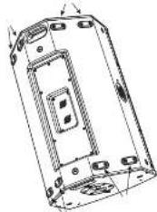
Feet
M10 Mounting Holes with Screws
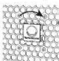
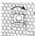
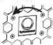
Badge Rotation
The horizontal badge is spring-fleaded and can be rotated by hand to suit vertical or horizontal positioning.
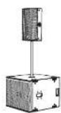
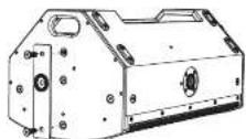
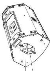
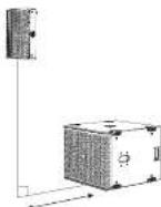
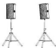
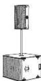
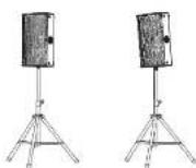
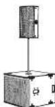
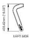
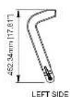
Pole Mount
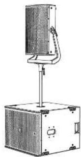
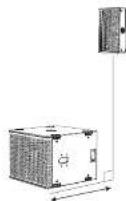
Two 15 mm holes are provided for pole mounting, one in the vertical position, and one with the PQ tilted downwards. The FO can be pole mounted on a PQ16 or KS12 tsubwoofer, or an a suitable Teflon stand.
We recommend using a 35 mmol with an H2AO throat at the lower end. This type provides more security and will screw into the top receptacle of the P0188 strawcooler.
QuickStart

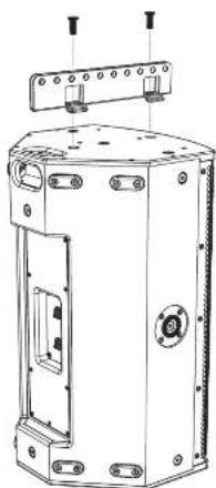
Fly Bar TQ FB
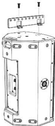
The optional TG-FB fly has allowed the speaker to be flown. The TG-FB for the P101, P102, and PQ15 speakers. It has ten pick points for attaching shudders, and it bolts to the top or bottom of the PO speaker.

The fly bolt fits to the top or bottom of the PO speaker using two of the existing M0 screws as shown. Securely tighten both screws.
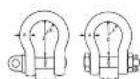
The flybot has 10~cm 12.5~mm diameter holes that are used as pick points for rigging shoals. The space between each rail of the TG FB allows for a standard 1 ton beam shoal to be used to pick up the PQ.
Either style of shackle will work.
W.1.1 = 1700
A=10mm
3.1mm
P=36.5mm
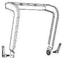
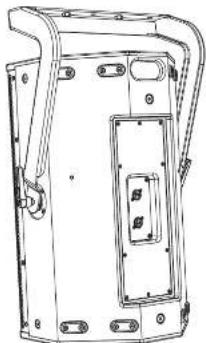
Yoke Bracket PQ10-YB, PQ12-YB, PQ15-YB
The optional yoke bracket allows the PG speakers to be flown using suitable hasch clamps or couplers to securely mount to a flown tuss. The yoke bracket is available in 2 sizes to fit each of the speakers in the PG series: PG10-YB, PG12-YB, and PG15-YB.
Rattatching handles are provided on either side to help angle the speakers accurately and secure them.
The yole bracket fits to the sides of the PQ speaker, by screwing the handles into the existing M10 mounting holes on each side. Note that the yole bracket is oriented as shown.
Adjust the speaker UI to the desired angle, and then tighten the handles to secure the speaker in position.
If the yoke bracket is to be bolted to a coiling or other surface, then secure the yoke bracket first.
Then lift the speaker and attach it to the pole bracket with the handles. Adjust the speaker angle and tighten the handles.
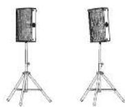
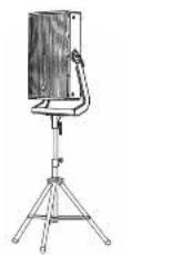
Pole Mount SA-35
The optional 5A-3S bracket allows the yoke bracket to support the PQ speaker on a 35mm pole mount or tripod. Note that the yoke bracket is oriented as shown.
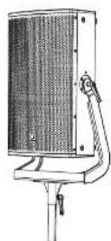
The SA 35 bracket attaches to the yoke bracket with two screws.
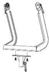
The assembly can then be added to a 35 mm pole mounted to a PQUB8 subwoofer, or to a suitable tripod stand. Tighten the Si-35 handle to secure the assembly to the pole or tripod. Adjust the speaker tilt as desired and tighten the handles on each side.
Quick Stee
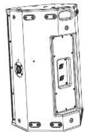
Suivel Bracket PQ10-SB, PO12-SB, and PO15-SB The optimal strutvec bracket allows the PQ speakers to be ceiling mounted horizontally or torsion-mounted using suitable hook clamps. The screw brackets is available in 3 sizes to fit each of the speakers in the PQ series: PO10_SB, PO12_SB, and PO15_SB.
The speaker angle can be accurately set and damped in position with the damphand scope.
Center the large washer, and then add the swivel bracket and secure it with the center screw and the handle screw.
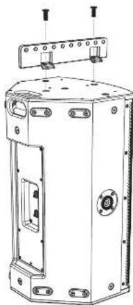
Follow the procedure below to rotate the home. Remove the grille by removing the five screens on each side.

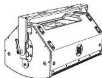
If the outer bracket is to be bolted to a ceiling or other surface, then secure the bracket first.
Add the small bracket to the top side of the PQ speaker, using the existing 3D mounting screw as shown.
Attach the large plate to the bottom of the speaker using the existing MFC screws. It covers the pole mount holes as shown.
Screw the other end of the swivel bracket with the supplied screw. Set the speaker at the desired angle and tighten the handle screw and center screws on either end of the swivel bracket.
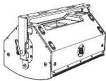
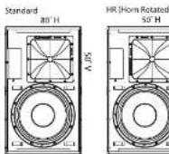
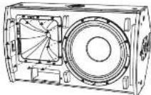
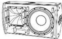
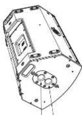
Horn Rotation
The MTH/HT Horn assembly provides an 80 degree horizontal beamwidth, and a 50 degree vertical beamwidth, when the FO is mounted vertically (photot).
The horn assembly can be removed and reinstalled in a different orientation to suit desired configurations and coverage. For example, if the speaker is used in landscape mode, you can rotate the horn to maintain the 80 degrees front/central and 60 degree vertical beamwidths. (This is a typical example of the need for horn rotation.)
The horn is marled on the front with the beampowerd angles.
Remove the 12 screws of the horn assembly.

Carefully pull the horn assembly forward, just enough to be able to rotate the assembly to the desired orientation.
Reinstal the horn with the 12 screws. Make sure the wiring is intact and not pickled.
Install the grill using ten screws, and make a note that the speaker has been modified.
Quick Start Guide
19
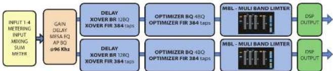
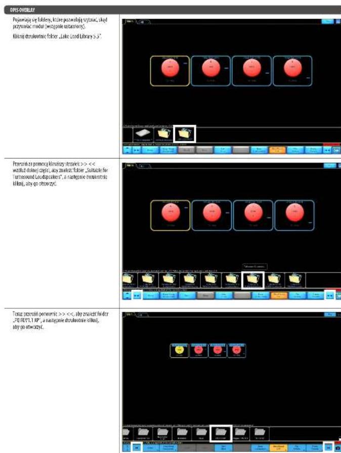
Lake Preset Overlays and Application Notes
All PQ series loudspeakers exclusively use Lake XP pre-sets via Lab Groupen PLM+ and O series I platforms and the forthcoming IPX /IR-X pre-sets. No other amplifier and DSP platforms are supported.
The PO series has a powerful yet simple pre-set strategy utilizing the latest functionality of Lake software, along with new BLC treechips. Pre-set data is found either via the Lake Load Library, or can be downloaded from www.turbosound.com
P010, P012, P015 leukspeakers each have individual 1 way passive FIR base pre-sets 1 channel DSP/AMPL, full range with or without Subroofers. The P018S subwoofer has an individual 1 way passive FIR base pre set (1 channel DSP/AMPL).
CAUTION: Do not combine PQ10, PQU, PQ15 loudspeakers on the same amplifier / DSP circuit. Failure to follow these instructions may lead to damage to the equipment.
CAUTION: Pay careful attention to output patching.
CAUTION: Pay careful attention to the HF Horn orientation, and select the HI preset if the HF Horn has been rotated.
PQ10, PQ12, PQ15, and PQ188 modules are based on the XP module from Lake software.
This QSG refers to REV.1 XP presents.
Lak software V7.0.7 or above must be used.
The download of the Lake controller includes the Lake Controller Operation Manual, which is a full tutorial of the Lake Controller and compatible hardware such as PLM1 series amplifiers.
Within this QSC, we focus on the Turboscound PQ series workflow and pre-set strategy, and assume basic working knowledge of the Lake Controller.
22PCSetes,QuickStartGuide 23
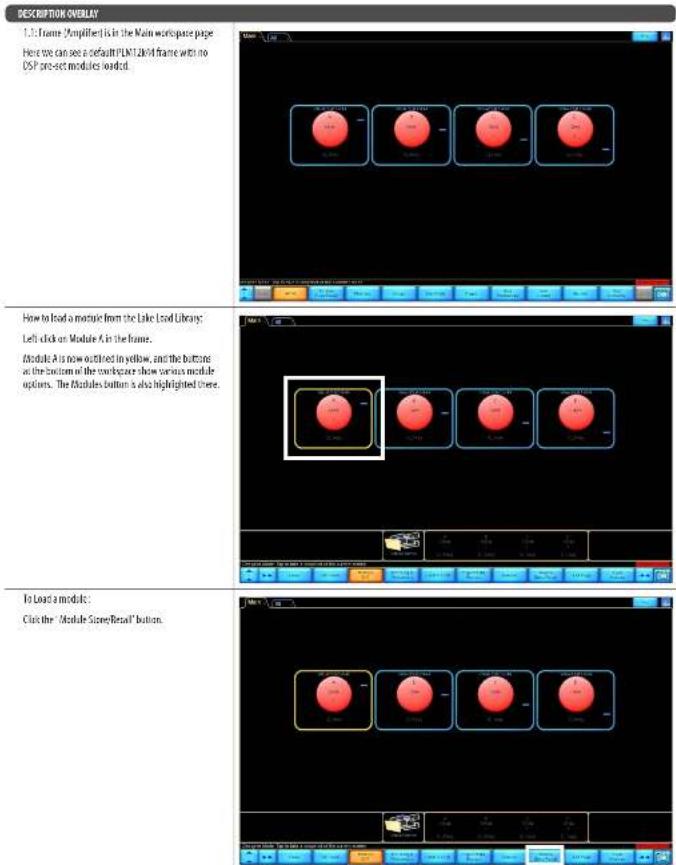
A
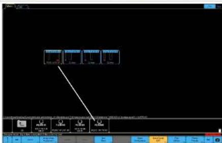
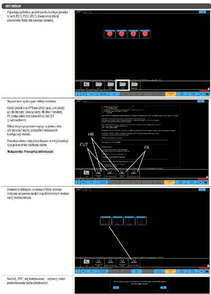
Finally agree, once for each speaker in the series 7010. The first one is a double check of the appropriate feeder for your speaker.
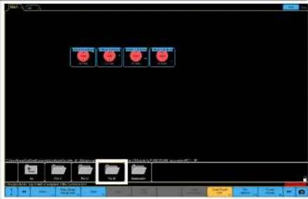
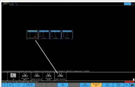
The available module holders are displayed.
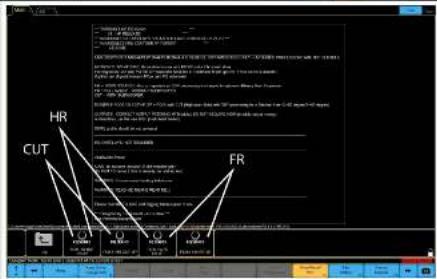
Each PI3 series speaker has four options, and oils depend upon the film orientation: standard, and HI (Film Rotatable, and FI. Full range without subwoofer or GTF with subwoofer).
Let us check whether these to show more details about the concrete set up.
The two insertion precursors is inserted in the initialization section of this quick start guide.
TIP: Please read the information!
Double-digit numbers the direct field will open the module pre-set in the highlighted module of the frame [amplifier].
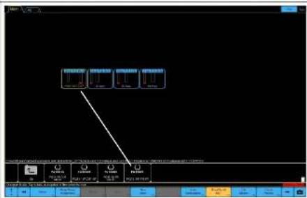
PRES:YES to proceed -the selected pre-split module is loaded

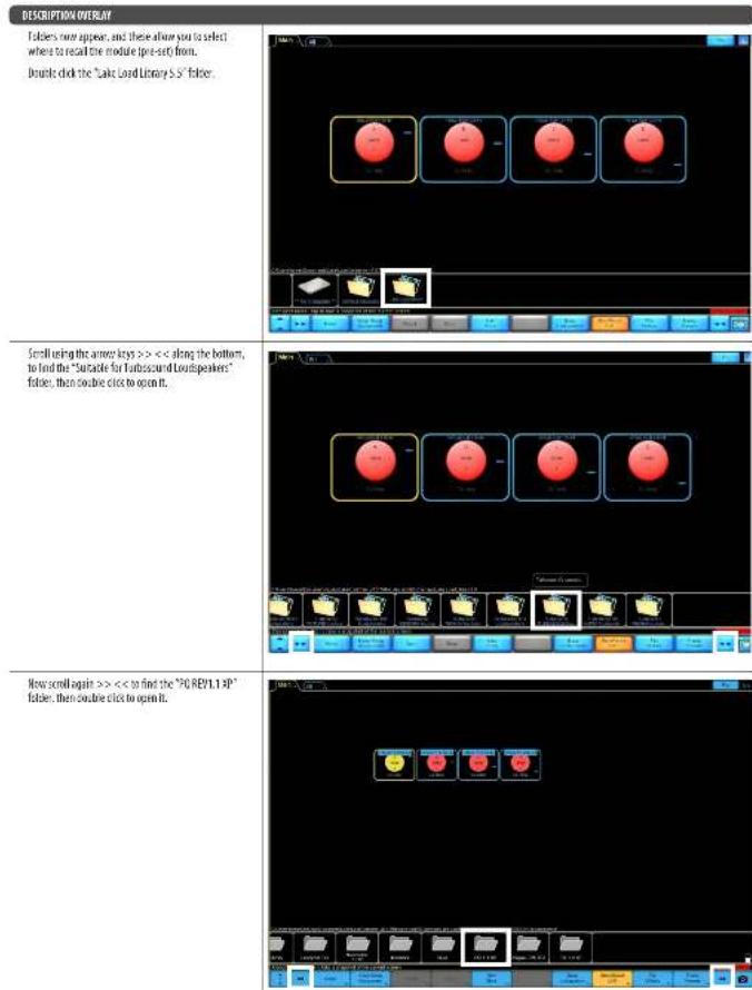
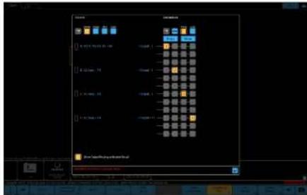
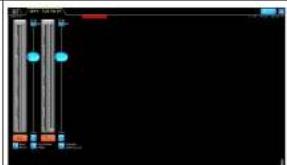
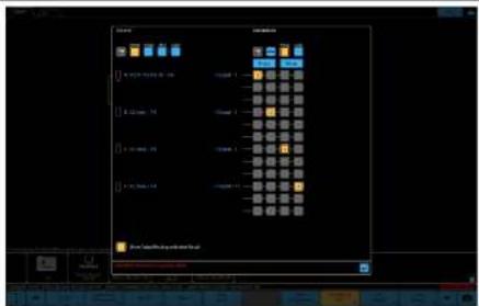
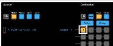
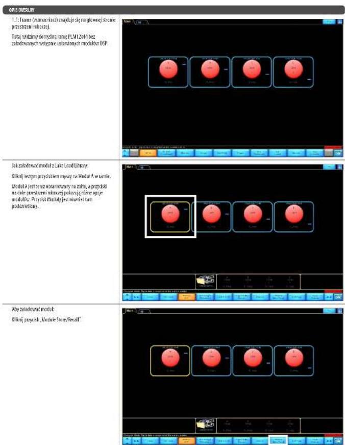
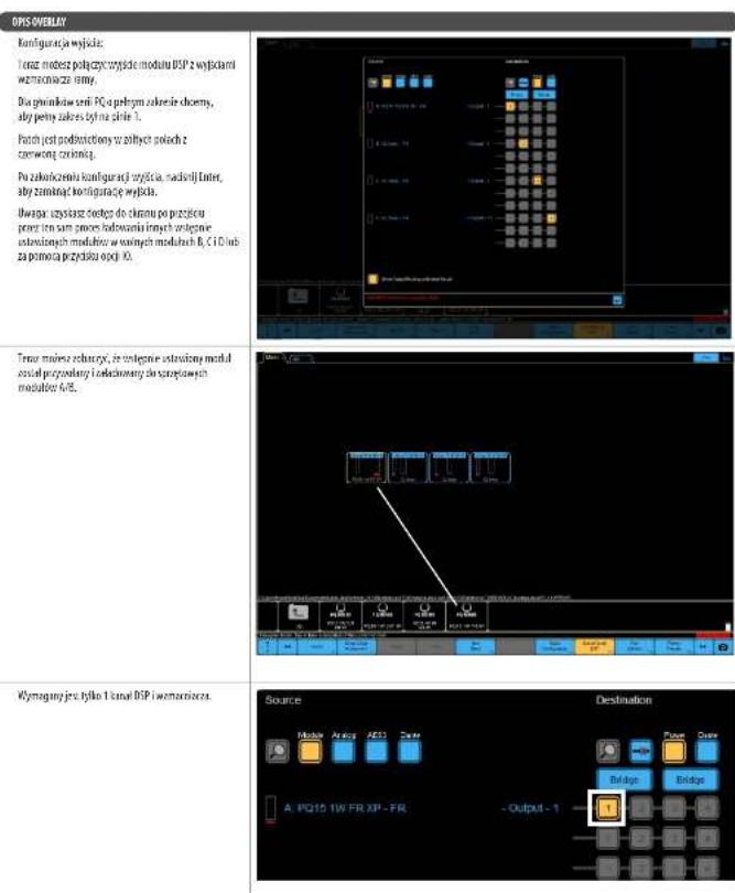
DESCRIPTION OVERLAY
How can you tan the DSP module output to the frame's amplifier outputs
For the full range 703 centers speakers must use full range. The patch is highlighted in yellow boxes on red dots.
Once you have finished the correct output patch, press enter to continue the output configuration
Note: you will get access to this screen once you go through the same process to find other project modules into the free B, C, and D modules or via the ID option button.
Now you can see the pre-set module is mangled and loaded into Hashmap modules.
only channel of DSP and amplifier are required

EN
24PC Series Quick Start Guide 25
GO STRATEGY ILLUSTRATION
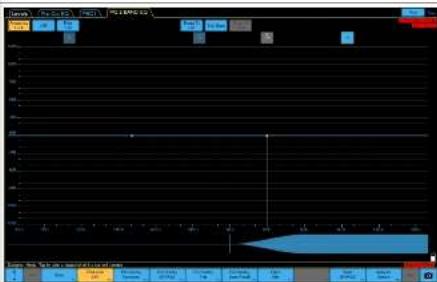
TnFQ10/7215speakehare a 2 band EQfllE
inserted.
The LIEO acts as a level control for UFHF and the 2 centre frequencies of the LIEO relate to the crossover points of the UFHF.
The SLOQ is offered two users to adjust total balance of the system. The first one is a system setting and group overview (system design dependency).
Examples of RE use
LF Con and HI Boost

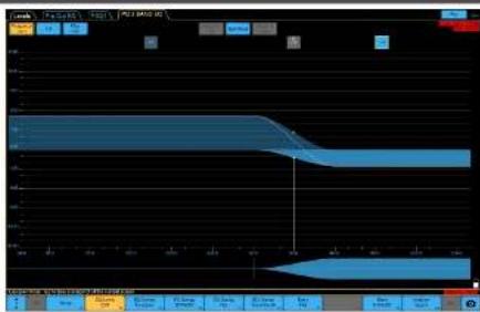
EO STRATEGYILLUSTRATION
IFBootandHCT
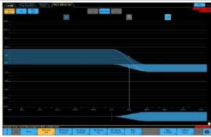
HF flow

EN
26PCeressQuickStartGuide 27
SUBWOOER STRATEGY ILLUSTRATION
The PUS88 subsolver has a power-law single Sub solver pre-set strategy:

CardioB
1.1rate
1 cabinet facing front, 1 cabinet facing back
Effective cardiolipin pattern
- Good reearjection
- Some compromise of confidence response
- Less efficient use of outflow

Combiiz:
21re
2cInesfingFront,1cInetfingBack
-Effectivecar
Good near rejection
Some compame of transients response
The best ratio for efficient use

Sound
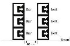
Injected End Fire
Info
From: abnct using FR0R1 presct
Rear cibnrs using REAR preset. Rear cibnrs facing
mment, at the line 32 ch mtefied and the map
- Electrictic cardiol 3
-6rod rea rejection
-Excluent transine response
Efficient use of subwoofers
- More physical depth required (500mm + 440mm - 362mm)
Traditional
- All jobiness facing Front
-Effective purposes direction
-Excluent translation response
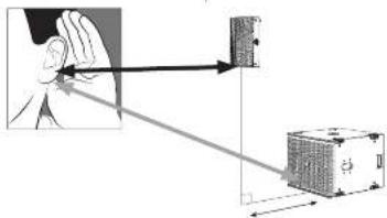
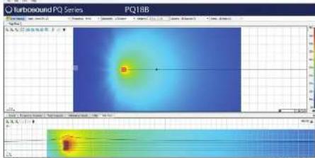
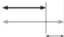
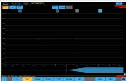
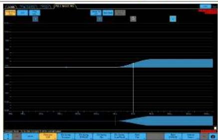
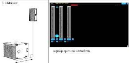
SUBTOFFETIMEALIGNMENTILLUSTRATIONOVERLAY
The POIRB subscripts pre uses all pass filters to set the initial time alignment assuming the front of the camera is in Im[ the greatly reduces system latency.
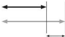
For example, if the fronts of the PQ speaker and autowire are aligned, then in both pre-sets, the delay should be set to zero default, which is done.
However, it is not always possible to have the down speakers and the ground stated has aligned in the vertical plane.
In this example, the sub is fixed of the quadrature, and so the sub needs to be delayed.

1. Subforward

Delay adjustment of sinus waveforms
2. How PQ is formed
Dea/adjustment of P0 screaler
- In this example, the neutron P01 speaker is 'forward' of the sub, and so the PO needs to be forward.
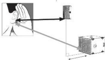
How do you find the correct delay time to align the flow程序员 to the ground studied brain?
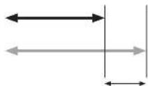
Some basic knowledge of delay can get you an acceptable result by measuring the distance between the tops of the flow spike and the front of the ground stacked away. Summer within the yellow zone you choose the delay unit, m/s, or less.
1.mls lndecrst -0.54 m (meter) - 1.235 d feet
Further further training can be done by using one of the many industry standard measurement software systems, reference microchips and other software packages. In addition, software integration to many of these software systems, and further information can be found at www.lattigroup.com.
Distance item is the difference to add to the lower array for attachment at the listening point.
Bienvenido
Grais po leiage a produto de attanances furoaund para aplicacion. I sfoe alteni mias informacion oeste uo produto, por force vieste myisto cto weh en turoanum.
Full EASE data can be downloaded from www.turbosound.com This will allow acoustic prediction, array formation and suspension to be determined. Important safety information about WLL is also calculated by EASE Focus.

Tiled DownwardsVertical
QuickStart

Barra de Vuelo TQ-FB
Attention: It is indispensable to utilize the provisions of the official directive on Lake. No part of the rules shall be taken off the basis of the provisions of the regulations of the competent authority.
Full EASE data can be downloaded from www.turbosound.com This will allow acoustic prediction, array formation and suspension to be determined. Important safety information about WLL is also calculated by EASE Focus.

Installation PQ10, PQ12, PQ15
Tiled DownwardsVertical
QuickStart
Barre de Suspension TQ-FB
Support de Poteau SA-35
S: Suppose prioritist don't be burette an unplanned on une aotre surface,foce of abred the boulder.
Full EASE data can be downloaded from www.turbosound.com This will allow acoustic prediction, array formation and suspension to be determined. Important safety information about WLL is also calculated by EASE Focus.


Installation PQ10,PQ12,PQ15

Tiled DownwardsVertical
A=10mm B=11mm C=17mm D=36.5mm


2. Hown PQ is forward
Cardioide BFF (traseira, frontal, frontal)
Full EASE data can be downloaded from www.turbosound.com This will allow acoustic prediction, array formation and suspension to be determined. Important safety information about WLL is also calculated by EASE Focus.

Instalacao PQ10, PQ12, PQ15

Tiled DownwardsVertical
QuickStart
Barra de Voo TQ-FB
Parametric: let alaten of laxa compete in a series PQ, quremar: laxa competes in PQ 1.
a patch of sand dehisced on creas amaculates with iron to the surface.
Dopoet de terminier a configura tion de sida corne, presse l'interne para fearchant a configura tion de salia.
Note: estrece a access a he bise dupeur de paserle ce ne meo preceur par corrugar ou les modiement preteins des maladies fauils B, C e o un attraite du botte de opio 10.
品 _ 出 之点可逆,故可设一个多项式偏微分法;
trapezoidal curve is a non-rotational surface of hard body.
2. How PQ is forward
Auste de aaso da anto fante PC
Cen exuminante tema de asisorti correto.
Cen exuminante tema de asisorti escondite.
Cen exuminante tema de asisorti es compres imputado no chao.
I. Il corriere mezzo libere unuubale di serae peccare eam un usiaticn antilivec, medici a disituta e a rivenza o la alto balanza suspensa e a franco delle cui in secolo 1500-1510 si erse che siusce software Late serpere eschiarulare un atutate di 4760, 78, 96, 126 pp.
1 ms [milliunm] = 0.543 m [meter] = 1.125 pts
I am ajsic fiue additional pule ser la leuna using a multistec systems of software in medico-patien de Industria, microfibres et retecratives de sem. O software Lube (Lube 1000) is the most popular system of software, which is information power system or control systems on www.lube.com.jp.
Full EASE data can be downloaded from www.turbosound.com This will allow acoustic prediction, array formation and suspension to be determined. Important safety information about WLL is also calculated by EASE Focus.


Tilted Downwards Vertical
A=10mm B=11mm C=17mm D=36.5mm


Tareck can be made winkels su and diaphragm uplinks per mode of insertion (deltacap) using a configuration similar to the one shown in Fig. 1.
If a possible order the 1 moduli preambience is a strict fibration coaction mod manifold hardware N8
Full EASE data can be downloaded from www.turbosound.com This will allow acoustic prediction, array formation and suspension to be determined. Important safety information about WLL is also calculated by EASE Focus.
B
图 1
Installatie PQ10,PQ12,PQ15
Veilghiehdewaarschwouting: Alien sevogden geocctfodcnpersenug mawanghende configuraties outgewen en installieren. Ongunde instalilte kan leisken tut de sboud of bilbvet ekje.
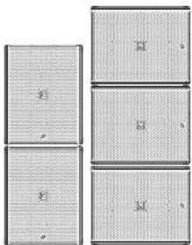
De PO138 can be used horizontal as vertical up de ground warden getaped.
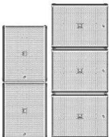
In verticelle positif megen siehrt three eitheden werden gestapelcd en in horizonte positif en maximum van die.
het wortwandelbaren um geschäfte spandionen.
rond de graep kasten te uroliden als extra.
welghtcemansteigre.
Presengeveen isn to winn via de Lake Load Library of kumnn worden gedownload op www.turbosound.com.
DE10-PO12- Po15- 19knebbers hohn klinikdme 1-wge passive FIR-bas-presit (K nainl DSP/AMP), full range met of znder subfawers. DE108-Subfowher be henn iinduside 1-wge passive FIR-bas-preist (K nainl DSP/AMP).
Lake XP-signalstroom:
De procurence此种 homoeatric wate bocheek in his installation ependance van de roe wortiglich.
Spawning is right to using this scheme rather than the explicit solution instead. This can be more convincing in modules in which B and C are modules for a scalar of size 16.
let me put all the controlling module as supervised in practice in A,B, and reconverts.
Frisdehns 1 canan an ESP er stederer noig.
NL
144FC Series Quick Start Guide 145
GO-STRATEGIEILLUSTATION
- In this context we should be in danger of:
- PO-Islandsickness - "we" of subcontinent,
- "we" of the sea,
- "we" of the land.
Although this is not yet available in most modern languages, it is likely to serve as a useful way of utilising the hostbastop.
148 FQ Series, Quick Start Guide 149
Välkommen
Tack for att du haur wait en Turbosound-hodgslare for im applikatiun. Dm du vill ha yterligare information em denna eler aligon annan product, beskr srl oreoplats p1 turbosound.com.
https://www.turbosound.com/downloads.html
Rekommenderade Lab Gruppen PLM+modelefor turneapikationer 4 PLM8k44,PLM12k44och PLM20k44.
For installation, send Andover Lab Groupen 4-seriers L-modeller, and And Lab Gruppoes CAFE-programa- tilligng for medi-dding fnd www.labgroupen.com - for at bestimmen der optimalisi Kasturkunstitionare bir dit system.
Systemkabelkray
For att undvika at sfa forkarknaf bor du anmna en krafng haglakbcd med en minstaTradipck pa 2.5 mm² [4 AWG, och hct 4 mm² (12 AWG) for fangr kere ar der dan total opdianen for hgalater n ir mare in beol. For extema kabelingand var medveton on kabelimpdoanon and resdansfander. Obwse atill korret palather.
Anvand akta 2xNL4M-kontakter for palindig drift.
First schisi higbtaa hinae rini dirs ius ticiuicn lill hiahbaacntn, s ati nigt bctyde ane vixt icil stkai apponas pihgtaa av inghkaahmaing.
Exempel pA Stereosystem
Cardioiod BFF (balk,fram,fram)
Med 4-kärnig NL4-kabel, 2 DSP-och 2 forstarkkanaler.
Ansluttingar
Full EASE data can be downloaded from www.turbosound.com This will allow acoustic prediction, array formation and suspension to be determined. Important safety information about WLL is also calculated by EASE Focus.

Installation PQ10, PQ12, PQ15
Sakkerhetsvantrag: Endust kroserad och ciecherted prinnul dirum annuca und inattula upogbana konfekturkner. Kefaligi installation kan teta hi'sdall'elle permanent skada.
Amending the secundar likerser et ar est obligatioris likerser.
Den medingdiga PG-hgtaenan ha kka uppsitngm nmed yfa foter for at lata hgtaen an semmonctor, bll integnere adl for statveon monitoring uM10 mntoringshai mad pasinde inesrassur.
PG-series kabinet ar informationed media intemai regkpong et for att passa minja miglia moniteriignerei depermanente installationes. Ala kabinet kan enklert hingus upm help alvaia M10-igor koppadie ill inte varikgekronnerne sone fsi tlligngas. To be dt Ermigka for kukurakura aenr cenn denum edugit umsara ha cniglinoq pe nare 18 mm Kabinetkan hingus upch onn e set diabetes. De vithia tibichiricamiglia att PG-oglikanu manionesi la filia stica konfiguracione
Fotter

M10-monteringshalmed skruvar
Rotation are emblem
Turbosound-emblemet in flidbetestat or hain
whites for hand for att. passiva verticali erler
horsentell positioning.
Stativmontering
T4.35 mm dtdiellanthilts for stantmentering,ent v. 1tiviklatte gich est met P0 lutad meit. P0 kon mentares pait et slatis on pa 10187 after M5121 subsofter, after e tiamlmpstknt.
V recommendant at du anvierer et 35 mm stare med en 2020 gars i eden medinde. Denn a typere silire sorknet archikan siosos in idren ove metagaren p 19 (BUB-ssowrden.

Tilted DownwardsVertical
FlygfasTe TQ-FB
Det valife T-8 Fyfifcater mllggyat higtigablatrban hygias. T-8 Fp baccar till higtiauna P010, P012 on P015.Den har to fspunktter for attsfa schackel e den butus nest paoppen eler botton av P6 higtiauna.
Flughäufiger moniensis je pappen icber boten ac P-ga-kaetanien mad npah yad to de beffingta M10-shovana sem visens. On at bhdka shovana ordariciat.
Fig.134 tabulated 10 haloed men aged pi a 12.5mm sum armrests sum fastpiston for eggshellcutdymestmel variae siana pTa-Fg birt stenstandardsbuckelpa t 1 tonan arvidundus for atiy yta P0.
For procedure ndan for all rotes home:
Taub gaiters genom att leuca de fem sbrannana p3 varile ska.

TaBOT de 12 skruwama pa hornets monitengscld.
3ra Erdolgiot fre hommoumertingen, bora thcdoigtot for anna ane aen the tllntic nittnng.
PIRIR has summarised this better than it can on its own for at least subheadless efft. but all of us are in plan yet. De fex et interet stansatite cathie M-10-montonghal med passante exeriseur
Markstapling
P1088 ran stipasi marker ink horizontal iller vertiak ridge.
I verkfallige triplas amendt und entherob och I horizontiert bieg tue.
Det rekmendrass att awandis limpiga sainmbard natt goppen as sabrett som ccn cctta schikertdgtt.
Rotation av Emblem
Turobund-erstelmert er faderbasiat atch kan erias for hand for att pasival terl her horstellc plarering.

Upphangning
P081K kagenet can erkeltig hup up mep hiip juv rivaia N10-igor Koppfalle t de inema igra unitera som bilanahsils. Is hert de bimogla foranikla surnara, es erst dm hed bogla motie ha en gilngnol o puii mir 40 mm.

Biparting Points

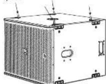
Eyeboils

M10 Shoulder Eye bolt
40mm
Stativmontering
Ett 35 mm hi tllhandnls for statvmonenting.
Hulthansigheptamine PI3 acetylates the full range of cells.
Patton at marked modula nina moti med tio.
Mira dur his slutti di lituagopassant, lyck pa miteri
at stima unigupsoncunfication.
10. Das kummarer at t qing hi sainen after te has got gum samn pross a rment for indus landa Ermadnai maute de la legh B- C- Sch b modulera eliuy 10 alternatenions.
BLLC erduis for amndare at jastera systemes
tansils tithamms med PEO-overog qch qupuwrata (lumules undermed)
Excmpdpl3BLEc-m3indnng
H2t
LF Conoh HF Boa

EO-STRATEGILLUSTPANTOM
LI Bunt sch HF Cat
IFnot

EN
SE
166PQ Series Quick Start Guide 167
SUBWOERESTATEGIIILLUSTRATION
P0185 subcutoffs for non-Kadish menetel strategy for subwave instabilities.

Gd012
1.1 好帖好评
I kabinet som varer harnak. I kabinet som varer harnak.
Effecti corticoidmestre
-Ba hake damping
- Vss komponents are overhoadsver
-Kindre effihty anming hao subnane
CarFood BFT
2:1-56mllandc
2 khattnnssvortarvat, 1 khattnnssvortar hukt
LifethertCarldmster
- fire basediming
- Vss komponis an oeransser
Bata forhianr for cthn annndng
Inverted End Fine
1:19thalfare
Frmcknntmrrrnnrnnn
Bekk
Bakai kibbutz som weite tamar, lago; kibbutz tere.
tive and veiels and tarey
Effectivcantiodmster
-Bue beke diuiping
- Ummark overdssan
- effects amending as subheaders
-Kermerfysstdjup560mm+400mm+
30mm
Tradorel
- Alkohneit, soter (harm)
-Effectonment
- Ummnt overnngsar
SUBWOER-TIOSUISTERINGILLUSTRATIONOVERLY
PQB: subterranea fischerlingungen anorder al-pan-fisher (for all taxa in del imia) tristener geotusant at flammertende pa kribent in irine), vitel metror systemenorientiert
In except on transforde
Po-togatcae sch subfremn er hirige, pa
Eetroginien hins bidingtinae maa stas in
pia stndernein, aikke 08.
Det at codicr citht aithi maigl att hte aphephthia hihmi d cdeqvistipn 10000000000000000000000000000
1.1 det h'expositifs en autocombinant fiuille Pcg-biologiques, au comboins microidis fiostas.
1. Subforward
Andromid (10) and stilbestrol are some kinds of ligands to the fibroglial amine for utilising with in vitro testing purposes.
168PQ Series Quick Start Guide 169
Witamy
Dreignay 2y yhoder prdikts kioiokovg rurbsos and do soejipakic, jst chesr uykac wicc) infarmaci o ty hain my production, owied naca strone internetwad pod adresr terrasound.
Rozpakowiegnejskia
Po rpoepawanu urzocniz deislae prcrot, cry ne u unoztcln. Jell zotny zwaa nztzuyn, natyzhnai povodn i wogne doztcag Yek ochohna, muzic olzochi wszchic uzocniz. Zachowiy slyzcko opakwanii no wspadk koriczkienoi delchina sprugny.
Full EASE data can be downloaded from www.turbosound.com This will allow acoustic prediction, array formation and suspension to be determined. Important safety information about WLL is also calculated by EASE Focus.
Tilted DownwardsVertical

Belka montaizowa TQ-FB
Opjorpalni hella moklauo T0-FB potzowla zanawcnei gloskiy. 18-Qa parae do gelskien PQ10, PQ121PQ3. Posta cichenei potzowla: zagczegowd o moczowia hakoi jert przygacna do gamsb lodeh ciepi cioski gloskiy
Soka montazawa jost mucawana do gomejui lab
dokyo credo geotika PQ puyuyu xushu
ismekychuk nib M16, kaj pacizawa. Dokyo mocma
cbe inkye.
176P Series, Quick (San Girds 177
Bukla montakwa posipasa 10 orowo o sredny, 12.5mm , kiree sa yugwue je kuroy zacerezi
da hikotz mokotochv. Ojostep mezlyka kisiya syaq T-4 Hontpwa na cytele standardenega haka
hukugo o o siredo 1cm tody pdoendersonia PQ.
Gbyotya styke hukotz beidu kishi:
W.L.L. = 1 ton
A=10mm B=11mm C=17mm D-36.5mm
Uchwyt PQ10-YB, PQ12-YB, PQ15-YB
Opipulnayt uchv tarnovla zavzacneiigoklenko PQ pyruzyu opodnichnyt raskov buzkienko, au yhepnie zammarov zamkruej na wizyazkratorenny. Uchvtont jest dostropy zu 1 mierianach, au yhepnie zei dozhukno zaglukovigoklenko serii PQ.PQD-YB, P012-YB1P013-YB. Po ouzhan zhadjiu zayevny zet nachrekta kote pamogna prazyscne iustruk nad nachyleniigoklenko i zabecsko.
P1383 more by: classifying a name to centroid[pi] pomcen|jub pomcen.
W orientaci zionpoj e ulukai makymajcne din cskaki, w posjemai makymajcne b7y.
Zaie de ubicte apodulesinl pas de zabepiecera gruy crobow jako daddictory srodck bepeciptzostiva.
Obrot emphelmatu
Embolizat Tundusociet (jct spcny)moi me go
boric cie, ay pasveu do plocey) hui
pocimje pocjci.
Zawieszenie
Chudobla 010826 mui by lataowawzomay prcny
aynu oipolnyh ncek 010 polyacryluy?
dostarocnymi weewotnymi pankamti
montaowy. Blum opolyechniy stby stoktowie i
zegiz be zozami, kuro musi mied dlagcu goutni co najnoj40 mm. Chudobla uynu by cawzemzne do go nagaryi, yei to konizncki.
M10 Shoulder Eyeboit 40 mm
Montaż na statywie
test dactyloper jorden oer a stedim 35 mm do montunca ma stacytse.
180PQ Series Quick Silt Guide 181
EN
PL
182PQ Series Quick Start Guide 183
184 PQ Series Quick Silet Guide 185
STRATEGICLOILLUSTRATIO
Groot P2012/15 mijt wachow 2 pramayr korector (BLO9)
BLO dea iae geolgatp oioiun da LIF, a 2
cscnnttccn cintre BLO gaoianz pumitni
paotluiL.
ELIC:etotomay,anyzuczykowjmytolldostoczkowywozyns coonary systemz zuklukti PLKtkihmiu gusnyzniykladyrod project systemi.
PryMdyuyxixBLOPl
CedeLiWzmscnienH

STRATEGIA EQ ILLUSTRATION
Wanonieir ficeeft

Vonconieir 4F
186PQ Series Quick Sile Guide 187
STRATEGIA SUBMOFFERALLUSTATION
| Subtotal POBR posada mikoj proteta strategje ustawien estepnayt susterowae. | Up | PO FB CARD | PO FTF B CARD | PO NEW END FINE | PO TRADITIONAL |
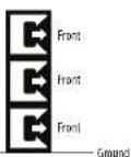
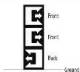
| Cardiolift Stussack 3:1 1 otuderns ulstralowane do pradodu, 1 otuderns sklenomaru do tyu • Skutcny woi kardiodani • Dabu elmarnac zdrwiku z tyu • Pielen kompromis od owodniadz przijidoreo • Knie wyapne wyskynztare uzubanemur | Back Front Ground | ||||
| Cardiolift Stussack 2:1 2 otuderns sklenomaru do pradodu, 1 otuderns sklenomaru do tyu • Skutcny woi kardiodani • Dabu elmarnac zdrwiku z tyu • Pielen kompromis od owodniadz przijidoreo • Knie wyapne stosunckla wystudene goykrystania | Front Front Back Ground | ||||
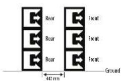
| Inserend Final Fin Stussack 1:1 Przeci tre ustralowaren z utazanemir Fikht Tjuru otuderns ulstralowaren RENL. Tjura skulny sklenomaru do pradodu, z tyu w ouwocarej dusztocmalaj madzery kaskowj • Skutcny woi kardiodani • Dabu elmarnac zdrwiku z tyu • Dabu elmarnac zdrwiku z tyu • Dabu elmarnac zdrwiku z tyu • Wyskyni wyskynztare uzubanemur • Wyskyni zdrwiku goydcia fozna 1562 mm + 440 mm + 560 mm | Rear Rear Rear Rear 440 mm | Front Front Front Ground | |||
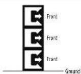
| Trzeciye • Wysykile ustralowaren sklenomaru do pradodu • Skutcny kralonny kordolny • Dabu ondewest przijidoreo cowi | Front Front Front Ground | ||||
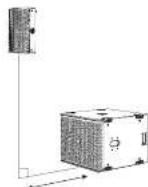
DOPASONANIE CZASUBWOOFERA ILLUSTRAION OVERLAY
Wigei stnssus subrodura P0185
zewilg flll al-ssdustkastria
pocotovorizopodoviridae casu cunatamcata
pcosmici pcoedch idy wvymenl,
sucrme amniscia enamine systema.
Naipokid selcrpedzic poecstria p01
subrofowera to wypwate, to the rothornph
sostoch rupichepens poywnny
extnne to nontrempdmping, cyll Fms.
dehna zawce jne iuttmdo wypwrate
zawcnoei dshnleur mncnfoedr
estnne h a dmern in pheromone sncn.
1.9 cm slynns subrodura zoujane v
zed (poteriknem P01 wrypsuderm fo
- 100mm double zipping shoe (P)
woopje shape (broaden)
wogshoe (toots)
knee arthroplasty (crisis, amputation)
abyssynovial (zinc alloy)
subcutaneous (sham/soil in arm)
AN的力是照上以小,最小1.5mm(14AWG),及安放4mm(12AWG)的点的八一元一元一元一元一元一元一元一元一元一元一元一元一元一元一元一元一元一元一元一元一元一元一元一元一元一元一元一元一元一元一元一元一元一元一元一元一元一元一元一元一元一元一元一元一元一元一元一
Full EASE data can be downloaded from www.turbosound.com This will allow acoustic prediction, array formation and suspension to be determined. Important safety information about WLL is also calculated by EASE Focus.

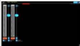
/1F/1F 1F/1F 1F/1F 1F/1F 1F/1F 1F/1F 1F/1F 1F/1F 1F/1F 1F/1F 1F/1F 1F/1F 1F/1F 1F/1F 1F/1F 1F/1F 1F/1F 1F/
Lake 135704-12-12-12-12-12-12-12-12-12-12-12-12-12-12-12-12-12-12-12-12-12-12-12-12-12-12-12-12-12-12-12-12-12-12
P01-21-54-11-11-11-11-11-11-11-11-11-11-11-11-11-11-11-11-11-11-11-11-11-11-11-11-
他のAPF0PFRF1-4
P01-1211111111111111111111111111111111111111111
P100L
Full EASE data can be downloaded from www.turbosound.com This will allow acoustic prediction, array formation and suspension to be determined. Important safety information about WLL is also calculated by EASE Focus.
安装 PQ10、PQ12、PQ15

Tilled Downwards Vertical
Quick Stee Guide 215
安装架TQ+B
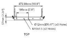
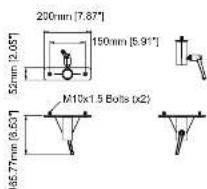
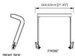
Dimensions (optional accessories)
PQ10-YB PQ12-YB
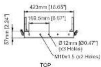

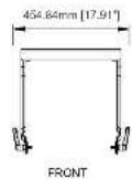

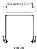
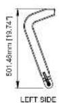
PQ15-YB SA-35
Quick Star Guide 231
EN
Specifications
| System P010-P012 P013 | |||
| Frequency response [-3 dB] | -70Hz-74Hz - 20Hz - 30Hz - 30Hz | ||
| Frequency response [-10 dB] | -20Hz-45Hz - 20Hz - 45Hz - 20Hz | ||
| Nominal dispersion [0-6 dB points) | \( 30^{\circ}\mathrm{H} + {50}^{\circ }\mathrm{V} \) | ||
| Power handling HEC' PSSM | LF: 350 W continuousHF: 50 W continuousHF: 400 W continuousHF: 1500 W continuous | LF: 520 W continuousHF: 50 W continuousHF: 550 W continuousHF: 2000 W peakHF: 200 W peakHF: 2000 W peak | LF: 520 W continuousHF: 50 W continuousHF: 550 W continuous |
| Peak | LF: 1400 V peakHF: 200 W peakHF: 1500 W peak | LF: 2000 V peakHF: 200 W peakHF: 2000 W peak | LF: 2000 V peakHF: 200 W peakHF: 2000 W peak |
| Sensitivity (1% to 1 mΩ) | 95 dB | 98 dB | 99 dB |
| Maximum SPI (FF) \( {}^{b} \) | 128 dB (134 dB peak) | 131 dB (137 dB peak) | 133 dB (138 dB peak) |
| Impedance | 8 Ω | ||
| Overpass type | Passive | ||
| Components | 1 x 10* (250 mm) Female IF driver | 1 x 10* (315 mm) Female IF driver | 1 x 10* (100 mm) Female IF driver |
| 1 x 1.5" (44.4 mm) side cell Politycle diaphragm, Neo Motor HF compression drivers | |||
| Endorse | |||
| Consignor | 3 x 14MM | ||
| Wiring | Pin 1+7-1 input, pins 2+7-2 link | ||
| Dimension:1/6 W×B | 545x473x120 mm(23.3x13.4x12.8") | 640x473x120 mm(24.8x14.7x12.9") | 712x530x383 mm(25.0x16.9x15.7") |
| Net weight | 158kg (35.24 lb.) | 236 kg (52.00 lb.) | 27.0 kg (59.52 lb.) |
| Construction | 12 mm and 15 mm "L" and "H" plywood | ||
| Finish | Black textured P8 paint | ||
| Slate | Powder coated perforated steel | ||
| Hlyng hardware | M10x14Peds | ||
| IP rating | IP4 | ||
| IR rating | 4-5 (ASTM G155-13) | ||
| accessories (optional) | |||
| Swivel Bracket | PQ10-SB | PQ12-SB | PQ15-SB |
| Yoke Bracket | PQ14-VB | PQ12-VB | PQ15-VB |
| Stand Adapter | SA-SS | ||
| Hy Bar | TO-SS | ||
| bag | PQ10-WPB | PQ12-WPB | PQ15-WPB |
Notes:
- Free field conditions. Measured at 1 metre on axis
- MTIC 288 standard with crest factor 6 dB pink noise.
- Calculated Peak based on the rated IR power using pitch noise with a rest factor of 4 dB, with dedicated pre-set.
232 BC Series
EN
Specifications
| System PUBB | |
| Frequency response (+3 dB) 45Hz - 200Hz | |
| Frequency response (10 dB) 32 Hz - 3 kHz | |
| Nominal dispersion (±6 dB points) Dmnl | |
| Power handling (SEC) 200V continuous, 2000P peak | |
| Sensitivity (1W ≤ mΩ 90 dB | |
| Maximum SPL 133 dB (330 dB peaks) | 1 |
| Impedance R0 | |
| Crossover type Passive | |
| Components | 4' Cooper voice call, FEM optimized motor and suspension system, dual silicon spacer 1x 10' (160 mm) Female UL driver |
| Exterior | |
| Connectors | Rear: 3.3 x NLR Front: 1x NLR |
| Wiring | Rear: 1/2 x NLR (pin 1/1-Input, 2/2-Link) Rear: Pin usage: 1 x 1.4 (pin 1+7- loop to pin 2+7, and pin 2-7- loop to pin 1-7) Front: 3 x NLR (pin 1+7, NC, 2-2-Input) |
| Dimensions HWD 520 x 640 x 687 (20.47 x 25.96 x 27.65) | |
| Net weight | 47.9 kg (105.6 lbs) |
| Construction | 15 mm and 18 mm" and "s" plugged |
| Finish | Block textured PU paint |
| Girle | Powder coated perforated steel |
| Flying hardware | M10 x 16 points |
| IP rating | IP4 |
| UV rating | 4.5 (65HB G155 13) |
| Accessories (optional) | |
| Plug | PU18B-4X |
| Wheels | Mindester wheels kit |
Notes:
1.Free field conditions Measured at 1 metre on axis.
2. MTBC 264 standard with test factor sft pink noise
3. Calculated Peak level at 1 mumber half space conditions using pink noise with a crel facte of 4 dB, with cedirated pre set.
Quick Stee Guide 233
技术参数
Other important information

Important information
- Register online. Please register your new Khokri Equipment right after you purchase it by visiting www.khokri.com. Registering your purchases using our simple write form helps us to process your repairs claims more quickly and efficiently. Also, read the items and conditions of our warranty. It's applicable.
- Malfunction. Should your Music Tribe Authorised Besnless be located in your vicinity, you may contact the Music Tribe Authorised Fulfiller for your country listed under "Support" at muscitrbc.com. Should your country not be listed, please check if your problem can be dealt with by our "Online Support" which may also be found under "Support" at muscitrbc.com. Alternatively, please submit an online warranty claim at muscitrbc.com BEFORE returning the product.
- Power Connections. Before plugging the unit into a power socket, please make sure you are using the correct main voltage for your particular model. Faults must be replaced with lists of the same type and noting without exception.

Informations importantes
Other important information

Herewith, Vector依法 declared that this product is in compliance with General Product Safety Regulation (B.9.2003/NSB, Directive 2011/65/EU) and Amendment 2015/863/EU, Directive 18/17/BT/84/TE, Regulation 1/9/2012 REACH/ICL and Directive 18/17/BT/84/TE, Directive 18/17/BT/84/TE, and the product is not applicable to LMC Directive 2014/863/EU, LV Directive 2014/35/EU.
Full text of EU BoC is available at https://community.muttribe.com/
EU Representative: Empower Tribe Innovations, DE GmbH
+4803-270-1690, E-mail: emper@euro.uzh.ch
UK Representative: Empower Trust Innovations UK Ltd.

Correct disposal of this product. This symbol indicates that this product must not be disposed of with household waste, according to the WEEL Directive (2012/9/EEU) and your national law. This product should be taken to a collection centered on the recycling of waste electrical and electronic equipment (EEL). The misstanding of this type of wastes could have a possible negative impact on the environment and human health due to potentially hazardous substances that are generally considered dangerous by the EU.
current disposal of this product will contribute to the efficient use of natural resources. For more information about where you can take your waste equipment for recycling, please contact your local city office, or your household waste collection service.
Quick Star Guide 237
EN