
iQ10 - Speaker Turbosound - Free user manual and instructions
Find the device manual for free iQ10 Turbosound in PDF.


| Product Type | Powered 2-way loudspeaker |
| Model | iQ10 |
| Brand | Turbosound |
| Frequency Response | 55 Hz - 18 kHz ±3 dB; 50 Hz - 25 kHz -10 dB |
| Nominal Dispersion | 90° H x 60° V (-6 dB points) |
| Maximum SPL | 129 dB peak |
| Transducers | 1 x 10" (256 mm) LF driver, 1 x 1" (25.4 mm) HF compression driver |
| Amplifier Power | 2500 W maximum output power, Class-D |
| Protection | Short circuit, open circuit, thermal, independent HF/LF peak and RMS limiters |
| Controls | Rotary push encoder, PROCESS, SETUP, EXIT, ENTER buttons |
| DSP Functions | Positioning, Sound mode, Speaker Modeling, FBQ, delay (0-300 ms), high/low shelving EQ, 2 parametric EQs |
| Presets | 20 total (19 user-definable, 1 factory default) |
| Connectivity | Input A/B: combo XLR/TRS; Output A/B: XLR; ULTRANET in/thru: RJ45; USB for remote control and firmware updates |
| Power Supply | Neutrik powerCON inlet and link; 120-240 V~, 50/60 Hz, 150 W consumption |
| Dimensions (H x W x D) | 526 x 324 x 316 mm (20.7 x 12.7 x 12.4 in) |
| Weight | 17.2 kg (58 lb) |
| Enclosure | Injection-moulded polypropylene, black painted |
| Grille | Powder coated perforated steel |
| Flying Hardware | M10 threaded points (3 on top) |
| Accessories (optional) | iQ10-WB wall/ceiling bracket, pole mount, castors (subwoofer only) |
| Networked Mains | PowerCON link for daisy-chaining up to 7 units |
| Compliance | FCC Class B, CE, ETL |
Frequently Asked Questions - iQ10 Turbosound
User questions about iQ10 Turbosound
0 question about this device. Answer the ones you know or ask your own.
Ask a new question about this device
Download the instructions for your Speaker in PDF format for free! Find your manual iQ10 - Turbosound and take your electronic device back in hand. On this page are published all the documents necessary for the use of your device. iQ10 by Turbosound.
USER MANUAL iQ10 Turbosound
natural_image
Exterior view of a set of black audio/video speakers on stands (no text or symbols visible)ES
FR
DE
PT
iQ Series
2500 Watt 2 Way 8"/10"/12"/15" Powered Loudspeaker 3000 Watt 15"/18" Powered Subwoofer KLARK TEKNIK DSP Technology, Speaker Modelling and ULTRANET Networking
2 C Series Quick Start Guide 3
EN
ES
Important Safety Instructions
Terminals marked with this symbol carry electrical current of sufficient magnitude to constitute risk of electric shocks. The only high quality professional speaker tables with 15" TS or twist locking plugs pre installed. All other installation or modification should be performed only by qualified personnel.
This symbol, wherever it appears, alerts you to the presence of uninsulated dangerous voltage inside the enclosure - voltage that may be sufficient to constitute a risk of shock.
This symbol, wherever it appears, alerts you to important operating and maintenance instructions in the accompanying literature. Please read the manual.
Caution To reduce the risk of electric shock, do not remove the top cover (or the rear section). No user serviceable parts inside. Refer servicing to qualified personnel.
Caution To reduce the risk of fire or electric shock, do not expose this appliance to rain and moisture. The apparatus shall not be exposed to dripping or splashing liquids and no objects filled with liquids, such as wares, shall be placed on the apparatus.
Caution These service instructions are for use by qualified service personnel only. To reduce the risk of electric shock do not perform any servicing other than that contained in the operation instructions. Repairs have to be performed by qualified service personnel.
- Read these instructions.
- Keep these instructions.
- Hreed all warnings
- Follow all instructions.
- Do not use this apparatus near water.
- Clean only with dry cloth
- In not block any ventilation openings, install in
accordance with the manufacturer's instructions. -
Do not install near any heat sources such as radiators, heat registers, stoves, or other apparatus (including amplifiers) that produce heat.
-
Do not defeat the safety purpose of the polarized or grounding-type plug. A polarized plug has two blades with one wider than the other. A grounding-type plug has two blades and a third grounding proing. The wide blade or the third proing are provided for your safety. If the provided plug does not fit into your outlet, consult an electrician for replacement of the obsoire outlet.
-
Protect the power cord from being walked on or pinched particularly at plugs, convenience receptacles, and the point where they eat from the apparatus.
-
Use only attachments/accessories specified by the manufacturer.

- Use only with the cart, stand, tripod, bracket, or table specified by the manufacturer, or sold with the apparatus. When a cart is used, use caution when moving the cart'apparatus combination to avoid
injury from tip-over
-
Unplug this apparatus during lightning storms or when unused for long periods of time.
-
Refer all servicing to qualified service personnel. Servicing is required when the apparatus has been damaged in any way, such as power supply cord or plug is damaged, liquid has been spilled or objects have fallen into the apparatus, the apparatus has been exposed to rain or moisture, does not operate normally, or has been dropped.
-
The apparatus shall be connected to a MANG socket outlet with a protective earthing connection.
-
Where the MAINS plug or an appliance coupler is used as the disconnect device, the disconnect device shall remain readily operable.

- Correct disposal of this product: This symbol indicates that this product must not be disposed of with household waste, according to the IEEE Directive (2012/19/EU), and your national law. This product should be taken
In a collection center licensed for the recycling of waste electrical and electronic equipment (EET). The mishandling of the type of waste could have a possible negative impact on the environment and human health due to potentially hazardous substances that are generally associated with EET. At the same time, your cooperation in the correct disposal of this product will contribute to the efficient use of natural resources. For more information about where you can take your waste equipment for recycling, phone contact your local city office, or your household waste collection service. 18. Do not install in a confined space, such as a book case or similar unit.
-
Do not place naked flame sources, such as lighted candles, on the apparatus.
-
Please keep the environmental aspects of battery disposal in mind. Batteries must be disposed-of at a battery collection point.
-
Use this apparatus in tropical and/or moderate climates.
LEGAL DISCLAIMER
MUSIC Tribe accepts no liability for any loss which may be suffered by any person who relies on their wholly or in part upon any description, photograph, or statements contained herein. Technical specifications, appearances and other information are subject to change without notice. All trademarks are the property of their respective owners: MIDAS, KLARK TERRIK, LAB GRUPPEN, LAKE, TANHOY, TURBOSOUND, TC ELECTRONIC, TC FILLICON, BEHRINGER, BUGERA and COOLAUDIO are trademarks or registered trademarks of MUSIC. Tribe Global Brands Ltd. © MUSIC. Tribe Global Brands Ltd. 2018 All rights reserved.
LIMITED WARRANTY
For the applicable warranty terms and conditions and additional information regarding MUSIC Tribe's Limited Warranty, please see complete details online at musictribe-warranty.
ES
BESCHRÄNKTE GARANTIE
Thank you for choosing a TURBOSOUND loudspeaker product for your application. If you would like further information about this or any other TURBOSOUND product, please visit our website at turbosound.com.
Unpacking the Loudspeaker
After unpacking the unit please check carefully for damage. If damage is found, please notify your supplier at once. You, the consignee, must instigate any claim. Please retain all packaging in case of future re-shipment.
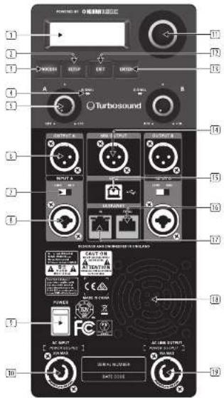
Controls
text_image
Labeled diagram of a turbosound device with numbered components and control knobs8 IC Series Quick Start Guide 9
① LCD SCREEN displays the current DSP module and parameter settings.
[2] SETUP button steps through parameters within DSP processing modules.
① PROCESS button steps through the DSP processing modules.
4 SIGNAL LED lights up to indicate the channel is receiving a signal.
[5] GAIN controls adjusts the analogue input level. To increase signal gain, rotate the controls clockwise; to reduce the gain, rotate the knobs counter-clockwise. (Fullrange models have separate GAIN knobs for channels A and B, while iQ15B and iQ18B subwoofers have a single dedicated A/B knob for both channels.)
OUTPUT A/OUTPUT B XLF connectors provide un-processed copies of the INPUT A or INPUT B signals.
LINE/MIC switch adjusts the input sensitivity for INPUT A and INPUT B.
INPUT A/INPUT B combo jacks accept input signals using XLR, balanced N° TRS or unbalanced N° TS connectors.
POWER switch turns the unit on and off.
AC INPUT accepts power connections from power cables fitted with Neutnk powerCOK twist-locking connectors.
11 ENCODER KNOB toggles between Graphic and Edit modes (when pressed) and changes parameter values (when rotated).
[12] EXIT button returns to the top-level DSP screen when pressed.
(1) ENTER button saves changes and deactivates Edit mode when pressed.
MIX OUTPUT XLB jack (unavailable on iQ15B and iQ18B subwoofers) sends out a post-GAIN signal composed of the summed INPUT A and INPUT B signals.
[15] USB connection enables firmware updates and remote control over parameters via computer. Please visit turbosound.com to download DSP control software for your computer.
ULTRANET THRU sends out unprocessed digital audio from the ULTRANET IN connector to additional ULTRANET equipped devices.
ULTRANET IN R45 plug comes with 2 limited green status LEDs. Whenever a CATS cable has been connected, and a valid ULTRANET signal is detected, both LEDs will light up simultaneously to indicate that the ULTRANET signal is ready to use.
18 VENTILATION FAN speed adjusts automatically to ensure trouble-free operation.
15 AC LINK OUTPUT connects power to other devices using power cables with Neutrik powerCOH twist-locking connectors.
Networking capability
All iQ powered loudspeakers offer remote control via USB. The USB connection allows the user to configure and monitor all DSP parameters using dedicated iQ software for PC.
The DSP firmware can also be updated via the USB connection. Visit turbosound.com for the latest firmware version.
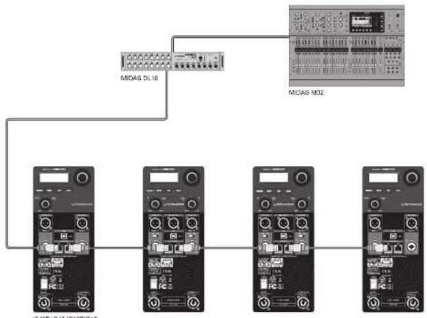
IQ speakers also offer proprietary ULTRANET networking capabilities through the ULTRANET IN and THRU connections using CATS cables with R45 connectors. ULTRANET allows the user to transmit undirectionally up to 16 independent channels of 24-bit audio throughout the IQ system, as well as other ULTRANET-equipped devices such as digital mixers and personal monitor systems. Up to 7 devices can be connected in series on a single ULTRANET cable. ULTRANET can also be used for remote control of the IQ selection of modeled speakers.
flowchart
graph TD
    A["MIDAS DL16"] --> B["MCOSA5 M02"]
    C["MCOSA5 M02"] --> D["MCOSA5 M02"]
    E["MCOSA5 M02"] --> F["MCOSA5 M02"]
    G["MCOSA5 M02"] --> H["MCOSA5 M02"]
ULTRARET connection with MIDAS M32 digital mixer and MIDAS DL 16 digital snake
1010 Series Quick Start Guide 11
Networked mains power
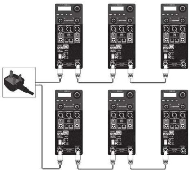
IQ loudspeakers also facilitate network transmission of mains power using power cables with Neutrik powerCOI locking power connectors. To set up networked mains power between IQ loudspeakers, first run a power cable terminating in a powerCOI connector to the AC INPUT connector on the rear panel. To power additional speakers dvemline, run power cables equipped with powerCOI connectors at both ends from the first speaker's AC LINK OUTPUT to the AC INPUT of the next IQ loudspeaker in series. The maximum number of linked systems depends on the AC supply voltage as well as the maximum current draw of the individual systems in the power chain. When linking a power chain, make sure that the integrated connectors as well as the supplied AC mains cable are never overloaded. If you are uncertain how to calculate the total current draw, please contact your dealer.
flowchart
graph TD
    A["Plug Symbol"] --> B["DC-DC Converter"]
    B --> C["Component 1: Power Supply"]
    B --> D["Component 2: Power Supply"]
    B --> E["Component 3: Power Supply"]
    B --> F["Component 4: Power Supply"]
    B --> G["Component 5: Power Supply"]
    B --> H["Component 6: Power Supply"]
    B --> I["Component 7: Power Supply"]
    B --> J["Component 8: Power Supply"]
    B --> K["Component 9: Power Supply"]
    B --> L["Component 10: Power Supply"]
    B --> M["Component 11: Power Supply"]
iQ speakers powered in series
iQ DSP Menu Structure
EN
| Fullrange Subwoofer Function | |||
 | Model "xyz" Model "xyz" | Choose from different sound models, either the URB0500D signature working or a DSP model of an industry standard product. | |
 | None None | Sets the frequency response to the default setting. | |
 | Live Live | Sets the frequency response to a typical live sound setting. | |
| Speech Speech | Sets the frequency response for optimal speech intelligibility. | ||
| Playback Playback | Sets the frequency response level for music playback. | ||
 | User User | Lets you defir the your own frequency response setting by entering the corresponding sub menu. | |
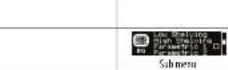
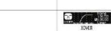 | Low/ High Shelving | Low/ High Shelving | Lets you define a low and high shelving filter. |
| Parametric 1 & 2 | Parametric 1 & 2 | Lets you defir the parametric bell type EQ frequency, Coat and Gault. | |
| None None | Unit is set for default full range/ subwoofer reproduction. | ||
 | — | iQ8 | Preset with local settings for use in combination with iX8 full range speaker. |
| — | iQ90 | Preset with local settings for use in combination with iI10 full range speaker. | |
| — | iQ12 | Preset with local settings for use in combination with iI12 full range speaker. | |
| — | iQ15 | Preset with local settings for use in combination with iI15 full range speaker. | |
| iQ15B — | Preset with high pass alignment for iQ15B subwoofer. | ||
| iQ18B — | Preset with high pass alignment for iQ18B subwoofer. | ||
| User User | User crossover sub menu for combination with other full range or subwoofer speaker systems. | ||
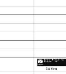
| Freq Freq | Select the desired crossover frequency: For Fullrange Systems 73 de to 400 Hz for Subwoofer Systems: 50 Hz to 150 Hz | ||
| Phase | Phase | Adjust the absolute phase (7" or 180") | |
12 IQ Series Quick Start Guide 13
| Fullimage Subwoofer Function | ||||
 | Auto Auto | Automatically uses many 6 items as required. Whenever a new feedback frequency is discovered, the first 8 liter will be released to attenuate the new frequency, and so forth | ||
| Single Single | Activate the FRO (feedback detection) functionality, up to 8 feedback 4 liters. | |||
| Learn Learn | Automatic procedure which searches for feedback frequencies and locks settings after all 8 items have been set.WDRAWING!Please use oat protection during this procedure. The feedback signal may approach the system's maximum level, which may cause hearing damage! | |||
| Reset Reset Reversal 1 liter. | ||||
| SETUP(page 1) | 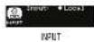 | Input Input | Lets you choose the audio input source. Choose between local (Andlogue Input) or ULTRAKET (e.g., P16 monitoring system or M22 audio via ULTRAKET). | |
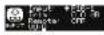 | Trim Trim | Adjusts the input gain of the ULTRAKET digital inputs in a range. In +10 dB to -30 dB | ||
| Remote Remote | Enables ULTRAKET remote control functionality in order to protect against misuse. | |||
| YU VU | Displays the respective input level of all 16 channels remaining via ULTRAKET, only while when ULTRAKET input is selected. | |||
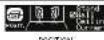 | Stand | Floor | For positioning the speaker on a pole mount stand (ultrange) or on the floor (subrocker). | |
| [1001M] | For positioning the speaker on or next to a wall (fixed install), alternatively as a monitor speaker (subedge). | |||
| Ceiling | - | For positioning the speaker on a wall next to the ceiling (fixed install). | ||
| Corner | Corner | For positioning the speaker in a corner next to the ceiling (fixed install). For positioning the speaker in a corner (subrocker). | ||
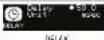 | Delay Delay | Adjusts the amount of delay (max 300msec = 105.85m or 358.19 feet). | ||
| Unit | Unit | Selects between msr, meter and feet. | ||
 | Limit | Limit | Adjust the limit threshold for the input signal from OFF up to ~30 dB. This threshold adjustment allows you to set a max output power which is below the full system's values may output. | |
| SELUP (log 21) | Version | Version | Displays the installed firmware version. | |
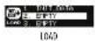 | 1.-20. | 1.-20. | To load a specific preset, turn the encoder to select the desired preset's number, and then other the ENTER button or the encoder. When asked to confirm press the encoder again or EXIT to short. | |
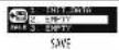 | 1.-20. | 1.-20. | To save a preset choose the remote pin preset slot and press ENTER or the encoder. | |
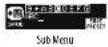 | Save Preset | Save Preset | Name the preset by checking the characters with the encoder and pressing to confirm each character. When Inhibit, press the ENTER button to save the preset. | |
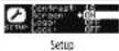 | Contrast | Contrast | Adjust LCD panel contact. The default contact value is 15. | |
 | Screen | Screen | OR LCD screen server (default) turns on automatically after approve. 2 minutes. OFF LCD turns off automatically after approve. 5 minutes. | |
| Logo | Logo | OFF-Declarates front panel logo illumination. OR Activities front panel logo illumination. LIMIT: logo will light up when the limiter is active. | ||
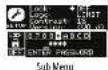 | Lock | Lock | Lock the device and create a password by checking the password characters with the encoder and pressing to confirm each character. When finished press the ENTER button, unlock the device by entering the password or connecting the unit via USB to a PC running Q software. The software does not require a password. | |
| Warning Warning | In case of overarching, an alert appears on the LCD screen, and the amplify will draw down until the unit orders. |
LCD Graphic Indicators
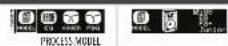
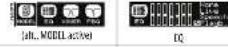
To help the user immediately recognize that a parameter has been selected and changed from the initial default setting, the parameter's related text on the top-level screen will invert and change to black text on a white background. As an example, the following screenshots show how the text for the MODEL function changes when the iOS default sound has been changed to the modeled PS8 sound:

This indicator function occurs only on the main DSP menu level and works for all DSP-related functions, except for the LOAD, SAVE and SETUP sub-sections on the second page of the top-level SETUP menu.
14 IQ Series Quick Start Guide 15
Mounting and fi xing
IQ series powered loudspeakers are designed with multiple internal rigging points to suit many possible mounting methods in permanent installations. All cabinets can be simply suspended using optional M10 eyebelts coupled to the internal rigging points provided on the top, bottom, sides and back. The simplest method is to use the two rigging points on the top and a single pull-back rigging point in the centre of the rear panel. Remove the appropriate plastic caps and insert eyebelts, which must have a thread length of at least 30 mm. Use the rear rigging point to angle the cabinet for optimum room coverage.
Wall and Ceiling Brackets
TURBOSOUND IQ8-W8, IQ10-W8, IQ12-W8 and IQ15-W8 wall and ceiling brackets are optionally available for IQ series.
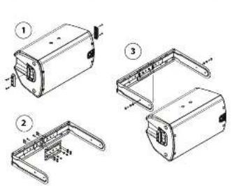
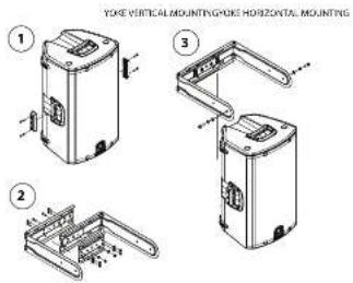
The graphic below shows the assembly of the optional mounting brackets (IQB-WB, IQ10-WB, IQ12-WB and IQ15-WB).
text_image
Technical diagram showing four views of a mechanical component with numbered annotations and dimension linesStep 1: Secure Yoke Spacers
| ITEM DESCRIPTION QUANTITY | ||
| 1 Valve spacer | 2 | |
| 2 | 12 5 x 25 mm screw with in/out thread locking | 6 |
Step 2: Assemble Steel Yoke Bracket: IQ12 and IQ15
| ITEM DESCRIPTION | NON QUANTITY | |
| 1 Steel yoke bracket 1 | 1 | |
| 2 Steel yoke bracket 2 | 1 | |
| 3 Steel yoke bracket 3 | 1 | |
| 4 KG plum voucher | 6 | |
| 5 KG x 16 min screw | 6 | |
| 6 KG nylon pinching nut | 6 |
text_image
YONE VERTICAL MOUNTING YONE HORIZONTAL MOUNTING ① ② ③Step 2: Assemble Steel Yoke Bracket: IQ8 and IQ10
| ITEM DESCRIPTION QUANTITY | ||
| 1 Steel yoke bracket 1 | 1 | |
| 2 Steel yoke bracket 2 | 1 | |
| 3 M/S x 15 mm screw | 2(∅8) 4(∅7) | |
| 4 M/S pin washer | 2(∅8) 4(∅10) | |
| 5 M/S my/um locking nut | 2(∅8) 4(∅10) | |
Step 3: Place Speaker Into Yoke Bracket
| ITEM DESCRIPTION QUANTITY | ||
| 1 Steel yoke bracket assembly | 1 | |
| 2 M8 x 25 mm screw | 2 | |
| 3 M8 plain washer | 2 | |
| 4 M8 spring lock washer | 2 |
NOTE: For IQ8 and IQ10, the finished bracket requires only 2 pieces, while the IQ12 and IQ15 bracket requires 3 pieces.
Pole Mounting
Fullrange iQ loudspeaker models (iQ8, iQ10, iQ12 and iQ15) may also be pole mounted, either independently or in conjunction with iQ subwoofer models (iQ15B, iQ18B). The iQ pole mount sockets allow fullrange models to be mounted straight or angled 7.5° downwards for optimum coverage.
1Q10, 1Q12 and 1Q15 models may also be placed on one side and deployed as wedge monitors. These models have been designed with sides angled at 43° to help with upward sound dispersion.
Transport
The subworkers are supplied with castors for ease of transportation when used as a portable sound system. To assemble the castors to the back of the cabinets, remove the 16 bolts from the rear of the speaker, align the castors with the mount holes and replace the bolts.
IMPORTANT NOTE: The mounting of a permanently installed sound system may be dangerous unless undertaken by qualified personnel with the required experience and certification to perform the necessary tasks. Walls, floors or ceilings must be capable of safely and securely supporting the actual load. The mounting accessory used must be safely and securely fixed both to the loudspeaker and to the wall, floor or ceiling.
When mounting digging components on walls, floors or ceilings, ensure that all fixings and fasteners used are of an appropriate size and load rating. Wall and ceiling claddings, and the construction and composition of walls and ceilings, all need to be taken into account when determining whether a particular fixing arrangement can be safely employed for a particular load. Cavity plugs or other specialist fixings, if required, must be of an appropriate type, and must be fitted and used in accordance with the maker's instructions.
The operation of your speaker cabinet as part of a flown system, if installed incorrectly and improperly, can potentially expose persons to serious health risks and even death. In addition, please ensure that electrical, mechanical and acoustic considerations are discussed with qualified and certified (by local state or national authorities) personnel prior to any installation or filing.
Make sure that speaker cabinets are set up and flown by qualified and certified personnel only, using dedicated equipment and original parts and components delivered with the unit. If any parts or components are missing please contact your Dealer before attempting to set up the system.
Be sure to observe the local, state and other safety regulations applicable in your country. MUSIC Group, including the MUSIC Group companies listed on the enclosed "Service Information Sheet", assumes no liability for any damage or personal injury resulting from improper use, installation or operation of the product. Regular checks must be conducted by qualified personnel to ensure that the system remains in a secure and stable condition. Make sure that, where the speaker is blown, the area underneath the speaker is free of human traffic. Do not fly the speaker in areas that can be entered or used by members of the public.
Speakers create a magnetic field, even if not in operation. Therefore, please keep all materials that can be affected by such fields (discs, computers, monitors, etc.) at a safe distance. A safe distance is usually between 1 and 2 metres.
16IQ Series Quick Start Guide 17
Technical Specifications
iQB iQ10 iQ12
| System | |||
| Frequency response | 60 Hz - 18 kHz ± 3 dB53 Hz - 20 kHz -10 dB | 55 Hz - 18 kHz ± 3 dB50 Hz - 25 kHz -10 dB | 52 Hz - 18 kHz ± 3 dB45 Hz - 20 kHz -10 dB |
| Nominal dispersion | 90°F x 90°F x 6-6 dB points | 90°F x 60°F x 6-6 dB points | 80°F x 60°F x 6-6 dB points |
| Maximum SPL 128 dB peak 129 dB peak 130 dB peak | |||
| Crossover type Active Active Active | |||
| Transducers | 1 x 8" (208 mm) LF driver1 x 11" (25.4 mm)HF compression driver | 1 x 10" (256 mm) LF driver1 x 11" (25.4 mm)HF compression driver | 1 x 12" (308.5 mm) LF driver1 x 11" (25.4 mm)HF compression driver |
| Limiter | Independent HF, LT,peak and rms | Independent HF, LT,peak and rms | Independent HF, LF,peak and rms |
| Amplifier | |||
| Maximum output power* | 2,500 V | 2,500 V | 2,500 V |
| Type | Class-D | Class-D | Class-D |
| Protection | Short circuit, open circuit, thermal | Short circuit, open circuit, thermal | Short circuit, open circuit, thermal |
| Connects | |||
| Input A / B | 2 x combo jack/UXLRine - 4 dBu, mic -22 dBu, switchable20 kΩ unbalanced, 40 kΩ balanced+21 dBu | 2 x combo jack/UXLRine - 4 dBu, mic -22 dBu, switchable20 kΩ unbalanced, 40 kΩ balanced+21 dBu | 2 x combo jack/UXLRine - 4 dBu, mic -22 dBu, switchable20 kΩ unbalanced, 40 kΩ balanced+21 dBu |
| SensitivityInput impedance | 2 x ALR Linked to inputXLR, balanced100 Ω unbalanced, 200 Ω balanced | 2 x ALR Linked to inputXLR, balanced100 Ω unbalanced, 200 Ω balanced | 2 x ALR Linked to inputXLR, balanced100 Ω unbalanced, 200 Ω balanced |
| Output A / BOutput impedance | 2 x R145 | 2 x R145 | 2 x R145 |
| Ultrameter input/Link | Neutrik powerCON input 20A and Link 15A | Neutrik powerCON input 20A and Link 15A | Neutrik powerCON input 20A and Link 15A |
| Mains Supply | Rotary push encoderButtons for PROCESS, SETUP, EXT, ENTER | Rotary push encoderButtons for PROCESS, SETUP, EXT, ENTER | Rotary push encoderButtons for PROCESS, SETUP, EXT, ENTER |
| Centrals | |||
| DSP | 2 x gain controls(channels A and B)2 x Line/NK switch | 2 x gain controls(channels A and B)2 x Line/NK switch | 2 x gain controls(channels A and B)2 x Line/NK switch |
| Mixer section | Positioning, Sound mode,Sound Modeling, FBQ | Positioning, Sound mode,Sound Modeling, FBQ | Positioning, Sound mode,Sound Modeling, FBQ |
| Display | LCD 128 x 52, blue baculit0 - 300 ms | LCD 128 x 52, blue baculit0 - 300 ms | LCD 128 x 52, blue baculit0 - 300 ms |
| Delay | |||
| Equalisation | High and low shelving FQ2 x parameteric EQ | High and low shelving FQ2 x parameteric EQ | High and low shelving FQ2 x parameteric EQ |
| Limiter | Zero attack input limiter | Zero attack input limiter | Zero attack input limiter |
| Presets | 20 total presets, 19 user-definable | 20 total presets, 19 user-definable | 20 total presets, 19 user-definable |
| Crossover | High Pass L R 24 dB/def | High Pass L R 24 dB/def | High Pass L R 24 dB/def |
| Protection | Lock-out function for all settings | Lock-out function for all settings | Lock-out function for all settings |
iQ8 iQ10 iQ12
| Ultranet Digital Network | |||
| System | |||
| Signal Latency | 16 channels < 0.9 ms | 16 channels < 0.9 ms | 16 channels < 0.9 ms |
| Cabling | |||
| Cables Cable length | Shielded CAT5 max. 246 ft / 75 m recommended | Shielded CAT5 max. 246 ft / 75 m recommended | Shielded CAT5 max. 246 ft / 75 m recommended |
| Power Supply | |||
| Power consumption | 150 W @ 5 min power | 150 W @ 5 min power | 150 W @ 5 min power |
| Voltage (fuses) | |||
| USA / Canada | 120 V~ 60 Hz (T 15 A H 250 V) | 120 V~ 60 Hz (T 15 A H 250 V) | 120 V~ 60 Hz (T 15 A H 250 V) |
| UK / Australia / Europe | 230-240 V~ 50/60 Hz(T 10 A H 250 V) | 230-240 V~ 50/60 Hz(T 10 A H 250 V) | 230-240 V~ 50/60 Hz(T 10 A H 250 V) |
| Korea / China | 230-240 V~ 50/60 Hz(T 10 A H 250 V) | 230-240 V~ 50/60 Hz(T 10 A H 250 V) | 230-240 V~ 50/60 Hz(T 10 A H 250 V) |
| Japan | 120 V~ 50/60 Hz (T 15 A H 250 V) | 100 V~ 50/60 Hz (T 15 A H 250 V) | 100 V~ 50/60 Hz (T 15 A H 250 V) |
| Endurance | |||
| Dimensions HAND | 457 x 2.79 x 2.99 mm(18.0 x 11.0 x 11.0") | 526 x 324 x 316 mm(20.7 x 12.7 x 12.4") | 689 x 370 x 370 mm(24.0 x 14.5 x 14.1") |
| Net weight | 14.7 kg (52 lb) | 17.2 kg (58 lb) | 21.1 kg (46 lb) |
| Construction | Injection-moulded polyspyrosilic enclosure | Injection-moulded polyspyrosilic enclosure | Injection-moulded polyspyrosilic enclosure |
| Finish | Black painted | Black painted | Black painted |
| Grille | Powder coated perforated steel | Powder coated perforated steel | Powder coated perforated steel |
| Flying hardware | M10 x 3 points | M10 x 3 points | M10 x 3 points |
| Accessories | |||
| IQB / NB Steel wall bracket | IQC / NB Steel wall bracket | IQJ2 / NB Steel wall bracket | |
18 IQ Series Quick Start Guide 19
Technical Specifications
iQ15 iQ15B iQ18B
| System | |||
| Frequency response | 50 Hz – 13 kHz ±3 dB42 Hz – 20 kHz -10 dB | 50 Hz – 130 Hz ±3 dB40 Hz – 130 Hz -10 dB | 50 Hz – 100 Hz ±3 dB36 Hz – 100 Hz -10 dB |
| Nominal dispersion 25^ H x 35^ W x 6 dB points Half Space Half Space | |||
| Maximum SPL 132 dB peak 130 dB peak 132 dB peak | |||
| Crossover type Active Active Active | |||
| Transducers | 1 x 1" (387 mm) LF driver1 x 1" (25.4 mm) HF compression driver | 1 x 15" (385.2 mm) LF driver | 1 x 18" (460 mm) LF driver |
| Limiter | Independent HF, LT, peak and rms | Peak and rms | Peak and rms |
| Amplifier | |||
| Maximum output power* | 2,500 W | 3,000 W | 3,000 W |
| Type | Class-0 | Class-0 | Class-0 |
| Protection | Short circuit, open circuit, thermal | Short circuit, open circuit, thermal | Short circuit, open circuit, thermal |
| Connects | |||
| Input A / B | 2 x combo jack/XLRLine -4 dBu, mic -22 dBu, switchable | 2 x combo jack/XLRLine -4 dBu | 2 x combo jack/XLRLine -4 dBu |
| Sensitivity | |||
| Input impedance | 20 kΩ unbalanced, 40 kΩ balanced | 20 kΩ unbalanced, 40 kΩ balanced | 20 kΩ unbalanced, 40 kΩ balanced |
| Maximum input level | ~21 dBu | +21 dBu | +21 dBu |
| Output A / B | 2 x XLR Limited to input | 2 x XLR Linked to input | 2 x XLR Linked to input |
| Mix output | XLR, balanced | N/A | N/A |
| Output impedance | 100 Ω unbalanced, 200 Ω balanced | N/A | N/A |
| Ultramet input/link | 2 x RAS | 2 x RAS | 2 x RAS |
| Mains Supply | Neutrik power/CKR input 20A and link 15A | Neutrik power/CKR input 20A and link 15A | Neutrik power/CKR input 20A and link 15A |
| Centrals | |||
| DSP | Rotary push encoderButtons for PROCESS, SETUP, EDT, ENTER | Rotary push encoderButtons for PROCESS, SETUP, EDT, ENTER | Rotary push encoderButtons for PROCESS, SETUP, EDT, ENTER |
| Mixer section | 2 x qubit controls(channels A and B)2 x Line/NK switch | 1 x qubit controls(channels A and B)2 x Line | 1 x qubit controls(channels A and B)2 x Line |
| User DSP Functions | |||
| Factory EQ presets | Positioning, Sound mode,Sound Modeling, FBQ | Positioning, Sound mode,Sound Modeling, FBQ | Positioning, Sound mode,Sound Modeling, FBQ |
| Display | LCD 128 x 32, blue backlit | LCD 128 x 32, blue backlit | LCD 128 x 32, blue backlit |
| Delay | 0 ~ 300 ms | 0 ~ 300 ms | 0 ~ 300 ms |
| Equalisation | High and low shelving FQ2 x parameters EQ | High and low shelving FQ2 x parameters EQ | High and low shelving FQ2 x parameters EQ |
| Limiter | Zero attack input limiter | Zero attack input limiter | Zero attack input limiter |
| Presets | 20 total presets, 19 user-definable | 20 total presets, 19 user-definable | 20 total presets, 19 user-definable |
| Crossover | High Pass L R 24 offset | Low Pass L R 24 offset | Low Pass L R 24 offset |
| Protection | Lock-out function for all settings | Lock-out function for all settings | Lock-out function for all settings |
iQ15 iQ15B iQ18B
| Ultramet Digital Network | |||
| System | |||
| SignalLatency | 16-channels< 0.9 ms | 16-channels< 0.9 ms | 16-channels< 0.9 ms |
| Cabling | |||
| CablesCable length | Shielded CATImax. 246 ft / 75 m recommended | Shielded CATImax. 246 ft / 75 m recommended | Shielded CATImax. 246 ft / 75 m recommended |
| Power Supply | |||
| Power consumption | 150 W @ 4 mm power | 200 W @ 5 mm power | 200 W @ 7 mm power |
| Voltage (fuses) | |||
| USA / Canada | 120 V~, 60 Hz (T 15 A H 250 V) | 120 V~, 60 Hz (T 15 A H 250 V) | 120 V~, 60 Hz (T 15 A H 250 V) |
| UK / Australia / Europe | 230-240 V~, 50/60 Hz(T 10 A H 250 V) | 230-240 V~, 50/60 Hz(T 10 A H 250 V) | 230-240 V~, 50/60 Hz(T 10 A H 250 V) |
| Korea / China | 230-240 V~, 50/60 Hz(T 10 A H 250 V) | 230-240 V~, 50/60 Hz(T 10 A H 250 V) | 230-240 V~, 50/60 Hz(T 10 A H 250 V) |
| Japan | 120 V~, 50/60 Hz (T 15 A H 250 V) | 120 V~, 50/60 Hz (T 15 A H 250 V) | 120 V~, 50/60 Hz (T 15 A H 250 V) |
| Endurance | |||
| Dimensions HAND | 711 x 450 x 381 mm(27.9 x 17.7 x 15.0") | 602 x 445 x 495 mm(23.7 x 17.5 x 19.5") | 691 x 533 x 559 mm(27.2 x 21.0 x 23.0") |
| Net weight | 26.1 kg (57 lbs) | 30.6 kg (67 lbs) | 39.8 kg (87.5 lbs) |
| Construction | Injection-moulded polypropylene enclosure | Birch plywood, screwed, and glued | Birch plywood, screwed, and glued |
| Finish | Black painted | Black painted | Black painted |
| Grille | Powder coated perforated steel | Powder coated perforated steel | Powder coated perforated steel |
| Flying hardware | M10 x 3 pellets | kPa | kPa |
| Accessories | |||
| IQ15 NW Steel wall bracket | |||
^a independent of limiters and other protection circuits
20 IQ Series Quick Start Guide 21
Other important information

Important information
-
Register online. Please register your new MUSIC Tribe equipment right after you purchase it by visiting turbosound.com. Registering your purchase using our simple online form helps us to process your repair claims more quickly and efficiently. Also, read the terms and conditions of our warranty, if applicable.
-
Malfunction. Should your MUSIC Tribe Authorized Reveller not be listed in your vicinity, you may contact the MUSIC Tribe Authorized Fertilizer for your country listed under "Support" at turbosound.com. Should your country not be listed, please check if your problem can be dealt with by our "Online Support" which may also be found under "Support" at turbosound.com. Alternatively, please submit an online warranty claim at turbosound.com BEFORE returning the product.
-
Power Connections. Before plugging the unit into a power socket, please make sure you are using the correct mains voltage for your particular model. Faulty fixes must be replaced with fixes of the same type and rating without exception.
FEDERAL COMMUNICATIONS COMMISSION COMPLIANCE INFORMATION

TURBOSOUND
iQ18B/iQ15B/iQ15/iQ12/iQ10/iQ8
Responsible Party Name: MUSIC Tribe Brands UK Ltd.
Address: Klark Industrial Park,
Walter Nash Road,
Kidderminster, Worcestershire,
DY11 7HJ United Kingdom
Phone Number: +44 1562 732290
iQ18B/iQ15B/iQ15/iQ12/iQ10/iQ8
This equipment has been tested and found to comply with the limits for a Class B digital device, pursuant to part 15 of the FCG rules. These limits are designed to provide reasonable protection against harmful interference in a residential installation. The equipment penetrates, uses and can radiate radio frequency energy and, if not installed and used in accordance with the instructions, may cause harmful interference to radio communications. However, there is no guarantee that interference will not occur in a particular installation. If this equipment does cause harmful interference to radio or television reception, which can be determined by turning the equipment off and on, the user is encouraged to try to correct the interference by one or more of the following measures:
• Reorient or relocate the receiving antenna.
- Increase the separation between the equipment and receiver.
- Connect the equipment into an outlet on a circuit different from that to which the receiver is connected.
- Consult the dealer or an experienced radio/TV technician for help.
This equipment complies with Part 15 of the FCC Rules. Operation is subject to the following two conditions:
(1) This device may not cause harmful interference, and
(2) This device must accept any interference received, including interference that may cause undesired operation.
Important information:
Changes or modifications to the equipment not expressly approved by MUSIC Tribe can void the user's authority to use the equipment.