HF 360 UP - Lighting STEINEL - Free user manual and instructions
Find the device manual for free HF 360 UP STEINEL in PDF.

| Product type | 360° microwave motion detector |
| Dimensions (H x W x D) | 80 x 80 x 55 mm |
| Power supply | 230 V, 50 Hz, three-wire connection (L, L', N) |
| Max. power (incandescent lamps) | 1000 W for 230 V AC |
| Max. power (fluorescent tubes / LED) | 500 W for cos φ=0.5, inductive load, 4 x 58 W max., C ≤ 88 μF |
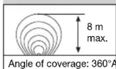
| Detection angle | 360° with 140° angular opening |
| Range | 1 - 8 m continuously adjustable |
| Twilight setting | 2 - 2000 lux, continuously adjustable |
| Time delay | 10 s - 30 min, continuously adjustable |
| Permanent light | Switchable (4 h) |
| Permanent Off | Switchable |
| Recommended mounting height | 1.1 to 2.2 m |
| Emission frequency | 5.8 GHz |
| Emission power | ~1 mW |
| Detection type | Active microwave, detection through thin walls (doors, windows) |
| Contact gap | μ, width < 1.2 mm between contacts at rest |
| Warranty | 36 months (repair or exchange) |
| Cleaning and maintenance | Damp cloth, no detergent |
| Safety instructions | Cut off power before any intervention |
| Applicable standards | Low Voltage Directive 2006/95/EC, EMC 2004/108/EC, R&TTE 1999/5/EC |
Frequently Asked Questions - HF 360 UP STEINEL
User questions about HF 360 UP STEINEL
0 question about this device. Answer the ones you know or ask your own.
Ask a new question about this device
Download the instructions for your Lighting in PDF format for free! Find your manual HF 360 UP - STEINEL and take your electronic device back in hand. On this page are published all the documents necessary for the use of your device. HF 360 UP by STEINEL.
USER MANUAL HF 360 UP STEINEL
SIO-4209ZacricaTel:+386/4231200
Fax:+386/42/312331-9f0@log.sq
SK Neco s.r.o. Ruizva ul. 111-SK-01901 Ieva
Tel: +421/42/4 45 67 10 - Fax: +421/42/4 45 67 11
www.neco.sk - neco@neco.sk
ROSteinel Distribution SRL - Parc industrial Metrom
RO-500269Brasov-Str.Carpatiknr.60
Tel.: +4002268 53 00 00 - Fax: +4001268 53 1
Installation Instructions
Dear Customer,
Congratulations on purchasing your new STEINEL Sensor Switch and thank you for the confidence you have shown in us. You have chosen a high-quality product that has been
manufactured, tested and packed with the greatest care. Please familiarise yourself with these instructions before attempting to install the Sensor Switch as prolonged reliable and
trouble-free operation will only be ensured if it is fittcd correctly. We hope your new Sensor Switch will give you lasting satisfaction.
System components
IR 180 UP:
①Flush box
② Basic element
(2) Basic element
(3) Cover frame
(4)Surround
Sensor unit
③Sensor unit
6 Button for permanent light and permanent light OFF
⑦ Permanent light and permanent light OFF indicator (red LED behind lens)
Catch
(Design shade for function adjustment, folding)
⑧Twilight setting
2-2000lux
10 Time setting 10 sec. -30 m
HE360UP:
①Euhbox
① Flash box ② Web page
(2) Basic element
③ Cover frame
念 Surveys
④ Surround
(5) Sensor unit
Button for permanent light and permanent light OFF
⑦ Permanent light and permanent light OFF indicator (red LED)
Catch
(Design shade for function adjustment, folding)
⑧Twilight setting
2-2009lux
2-200610X
Time setting
10 sec. - 30 min.
①Beach setting
1-8m
NF 50 UP:
① Flush box.
④ Flash box ⑤ Basic element
(2) Basic element
③ Cover frame
Surroundd
④ Sunround
(5) Sensor unit
Orientation light (red LED)

Safety instructions
Disconnect the power supply before any work on the Sensor Switch!
During installation, the electric power cable to be connected must be voltage-free. Therefore,
switch OFF the power fi rst and check freedom from voltage with a voltage tester.
Installation of the Sensor Switch involves work on the mains power supply;
this work must therefore be carried out professionally in accordance with regulations.
Principle
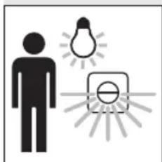
With the IR 180 UP and HF 360 UP sensor switches, groping for the light switch is finally a thing of the past! The intelligent sensor technology switches the light ON
automatically on entering the room and OFF again after the preset time. This is not only extremely convenient, but also increases safety and is energy and
cost saving. The NF 50 UP has a near fi eld sensor for contact-free switching.
IR 180 UP: HF 360 UP:
NF 50 UP:
The IR 180 UP is equipped with a pyro sensor which detects the invisible heat emitted by moving objects (pedestrians, animals etc.). The heat thus detected is electronically converted and switches ON connected consumers (e.g. a light). No heat radiation is detected through obstacles, such as walls or glass and no switching therefore occurs.
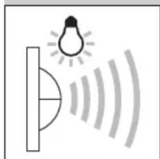
The HF 360 UP is an active motion detector. It reacts independently of temperature to the slightest movement. The integrated HF sensor transmits high frequency electromagnetic waves (5.8 GHz) and receives their echo. In response to the slightest movement in the detection zone, the change in echo is perceived by the sensor. A microprocessor subsequently triggers almost without delay the switching command, light ON. Detection is possible through doors, panes of glass or thin walls.
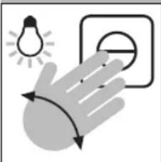
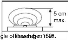
The NF 50 UP has a near field sensor system that allows contact-free ON and OFF switching of installed lights. Switching of the light is therefore possible with damp or dirty hands. The switch is triggered by a movement of the hand at a distance of max. 5 cm.
Technical specifications
| IR 180 UP: NF 50 UP:HF 360 UP: | |||
| Dimensions: | (H x W x D) 80 x 80 x 55 mm | ||
| Output: | |||
| Filament bulbs, 1000 W max., operating on 230 V AC Fluorescent lamp, 500 W max., at cos φ = 0.5, inductive load at 230 V AC 4 x 58 W each max., C ≤ 88 μF operating on 230 V AC \( ^{1)} \) | |||
| Connection: | 230 V, 50 Hz3-lead connection (L, L', N) | ||
| Contact gap: | μ, contact clearance of less than 1.2 mm between the contacts when unit is switched off. | ||
| Installation height: | approx. 1.1 + 2.2 m \( ^{2)} \) | approx. 1.1 + 2.2 m \( ^{2)} \) | approx. 1.1 m |
| Sensor technology: | Infrared sensor | 5.8 GhzHigh frequency | 5.8 GhzHigh frequency |
| Transmission output: | - | approx. 1 mW | approx. 1 mW |
| Angle of coverage: | \( 180^{\circ} \) with \( 90^{\circ} \) angle of aperture | \( 360^{\circ} \) with \( 140^{\circ} \) angle of aperture | - |
| Reach: | max. 8 m | 1 - 8 mcontinuously adjustable | approx. 5 cm |
| Twilight setting: | 2 - 2000 lux | 2 - 2000 lux | - |
| Time setting: | 10 sec. - 30 min. | 10 sec. - 30 min. | - |
| Permanent light: | switchable (4 h) | switchable (4 h) | - |
| Permanent light OFF: | switchable | switchable | - |
| Orientation light: | - | - | red LED |
*1) Fluorescent lamps, low-energy bulbs, LED lights with electronic ballast (total capacity of all connected ballasts below the value specified),
^2) Installation above a door.
Installation
Note for IR 180 UP:
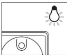
The installation position should be at least 1 m from a light, since heat radiation may trigger the system.
Installation procedure:
- Pull the mains lead out of the flush box and strip the insulation from the individual leads.
Connecting the supply
lead (refer to III, on page 5) The mains lead consists of a 3 phase cable.
L = phase conductor (usually black or brown) N = neutral conductor (usually blue)
L^ = phase conductor (usually black or brown) If in doubt, the cable must be identified with a voltage tester. Switch OFF the current again. Phases (L) and (L^) in addition to the neutral
IR 180 UP / HF 360 UP / NF 50 UP)
conductor (N) are connected to the terminal block. A protective-earth conductor is not required.
Important: Reversing the connections may result in damage to the unit.
- Push the basic element ② into the flush box ① and arrange horizontally. Take care that the cables are not pinched. Tighten both screws on the expansion claw until the basic element is firmly seated or screw with socket fi xing screws on the support ring.
- Apply the cover frame ③ and surround ④ and carefully mount the sensor unit ⑤ without tilting.
- Once the mains connection has been made, the sensor switch can be op
erated (refer to Functions section).
Only IR 180 UP and HF 360 UP:
The adjustment controls for the functions are concealed behind the folding design shade. Push in the catch on the sensor unit with a screwdriver and fold the design shade forwards.
Note:
Parallel switching of IR 180 UP and HF 360 UP is possible. Nevertheless, a neutral lead must be present on each flush box. The max. output to be switched does not increase as a result.
Functions
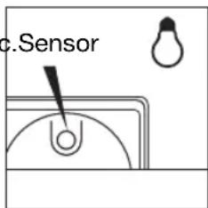
Contact-free switching
Move your hand in front of the sensor unit at a distance of max. 5 cm and the connected light will switch ON.The procedure is equally simple when switching OFF.
(only for NF 50 UP)
Orientation light
The Sensor Switch NF 50 UP is equipped with a red LED. This serves as an orientation light in the dark, so that the switch is easier to find.
Note:
Parallel switching or exchange of an existing two-way circuit is not possible.
Functions
only for HF 360 UP)
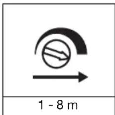
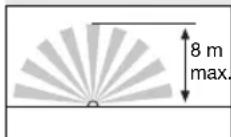
Reach setting (sensitivity) 10
The term reach denotes the approximately circular diameter that results as the detection zone.
Adjusting screw left stop position means: minimum reach (approx. 1 m / factory setting). Adjusting screw right stop position means: maximum reach approx.8m
Functions
only for IR 180 UP and HF 360 UP
Twilight setting
(Response threshold) ⑨ The desired sensor response threshold can be adjusted continuously from approx. 2 lux to 2000 lux. Adjusting screw right stop position means: Daylight operation approx. 2000 lux (factory setting). Adjusting screw left stop position means: Night-time operation approx. 2 lux.
Time setting
(Switch-off delay) 10
The desired duration of illumination of the connected light can be continuously adjusted from approx. 10 sec. to max. 30 min.
Adjusting screw left stop position means: shortest time approx. 10 sec. (factory setting)
Adjusting screw right stop position means: longest time approx. 30 min.
The timer is restarted by any motion detected before this time elapses.
When adjusting the detection zone and for the performance test in daylight, the adjusting screw must be set to the RH stop position.
The shortest time setting is recommended when adjusting the detection zone and performing a functional test.
Note: After every off switching, further motion detection is interrupted for approx. 2 seconds. Only after this time elapses is it possible for the Sensor Switch to switch light again.
Button for light functions (only for IR 180 UP and HF 360 UP)
10 sec. - 30 min. max. 4 hours OFF
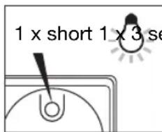
Permanent light mode Button 1 x ON
The connected light is set to permanent light for 4 hours (red LED illuminates). After this period, the Sensor Switch immediately returns to sensor mode (red LED OFF). Permanent light can be interrupted before this time elapses by pressing the button (red LED OFF).
Permanent light OFF mode Press button for 3 sec. The connected light is switched OFF (red LED fl ashes). By briefy pressing the button again, the Sensor Switch returns immediately to sensor mode (red LED OFF).
10 sec. - 30 min.
| Troubleshooting | (IR 180 UP / HF 360 UP / NF 50 UP) | Operation/Maintenance | ||
| Malfunction | Cause | Remedy | The Sensor Switch is suit-able for automatic or contact-free switching (NF 50 UP) of light. The unit is not suitable for special burglary alarm systems, since it lacks | the sabotage protection pre-scribed for this purpose. The surface should be cleaned if dirty with a damp cloth (without cleaners). |
| Sensor Switch without power | ■ Fuse blown, not switched ON | ■ Replace fuse; switch ON mains switch; check wiring with voltage tester | Check connectionsNF 50 UP not capable of two-way switch operation | The product complies with the following directives:Low voltage directive 2006/95/EC with amendmentEMC directive 2004/108/EC with amendment |
| Sensor Switch does not switch ON | Light bulb burnt out | ■ Replace light bulb | Declaration of conformityThe product complies with the following directives:Low voltage directive 2006/95/EC with amendment | HF 360 AP:R & TTE guideline 1999/5/EC with amendments concerning radio units and telecommunication facilities |
| Troubleshooting | (only for IR 180 UP / HF 360 UP) | |||
| Malfunction | Cause | Remedy | Functional Warranty | |
| Sensor Switch does not switch ON | Twilight setting in night-time mode during daytime operationAdditional two-way switch OFFFuse blown | ReadjustSwitch power onNew fuse, check connection if required | ||
| Sensor Switch does not switch OFF | Continued movement within the detection zoneSwitched ON light is within detection zone of IR 180 UP and switches ON again as a result of temperature changePermanent light operation switched ON(red LED illuminates)Other Sensor Switch is parallel-connected and still active | Check detection zoneCheck detection zoneSwitch off permanent light operationAwait time setting of the other Sensor Switch | This STEINEL product has been manufactured with great care, and its operation and safety have been tested in conformity with the current regulations. Production is also submitted to fi nal random-sample testing. STEINEL undertakes the guarantee for perfect condition and function. | The warranty period is 36 months, starting on the date of sale to the user.We undertake to remedy faults caused by material or manufacturing defects.This warranty undertaking shall be performed by the repair or replacement of the defective parts, at our own discretion.This warranty shall not cover damage to wearing parts or damage and faults caused by incorrect operation or maintenance.Further consequential damage to external items is excluded.Repair Service:Our Customer Department will not be covered by the warrantyPlease send the well packed to the Service Centre |
| Sensor Switch keeps switching ON/OFF | Switched ON light is within IR 180 UP detection zoneAnimals moving in IR 180 UP detection zoneCurtains, fl owners, etc. move within the detection zone of the HF 360 UP and cause switching again by motion | Check detection zoneCheck detection zoneCheck detection zone | ||

Ajuste do alcance (sensibility) ①
Gjelder for IR 180 UP:
Avstanden mellom monteringsstedet og en lampe ma vare minst 1 m, ellers kan varneutstråring fra lampen fore til at systemet reagerer.