SB 3116RMN - Drill Holzmann - Free user manual and instructions
Find the device manual for free SB 3116RMN Holzmann in PDF.

User questions about SB 3116RMN Holzmann
0 question about this device. Answer the ones you know or ask your own.
Ask a new question about this device
Download the instructions for your Drill in PDF format for free! Find your manual SB 3116RMN - Holzmann and take your electronic device back in hand. On this page are published all the documents necessary for the use of your device. SB 3116RMN by Holzmann.
USER MANUAL SB 3116RMN Holzmann
10.2 Technical details 35
10.3 Delivery content 35
10.3.1 SB 3116RHN 35
10.3.2 SB 3116RMN 35
11 SAFETY 36
11.1 Intended Use 36
11.2 Security instructions 37
11.3 Remaining risk factors 39
12 ASSEMBLY 40
12.1 Delivery content 40
12.2 Preparatory activities 40
12.2.1 Workplace requirements 40
12.2.2 Transport 40
12.2.3Preparation of the surface 40
12.3 Power supply 41
12.4 Assembly 42
12.5 Assembly spindle protection 44
13 OPERATION 45
13.1 Operation instructions 45
13.2 Operation 46
13.2.1 Spindle speed 46
13.2.2 Table 46
13.2.3 Adjusting head angle 47
13.2.4 Adjusting head horizontally 47
13.2.5 Adjusting specified drill depth 47
14 MAINTENANCE 48
14.1 Maintenance plan 48
14.2 Cleaning 48
14.3 Disposal 48
15 TROUBLE SHOOTING 49
16 PREFACIO (ES) 50
17 CHARACTERISTICAS TECNicas 51
17.1 Descripción de SB 3116RHN Fig. 1.1.51
17.2 Ficha的技术e de SB 3116RHN .52
17.3 Descripción de SB 3116RMN Fig. 1.2.53
17.4 Ficha的技术e de SB 3116RMN .54
EN EC-CONFORM: This product complies with EC-directives
EN READ THE MANUAL! Read the user and maintenance manual carefully and get familiar with the controls in order to use the machine correctly and to avoid injuries and machine defects.
ATTENTION! Ignoring the safety signs and warnings applied on the machine as well as ignoring the security and operating instructions can cause serious injuries and even lead to death.
ES
Protective clothing!
ES
EN Operation with long hair forbidden!
EN Do not climb onto the machine!
EN Warning about cut injuries!
EN Warning of rotating parts!
EN Warning against thrown-off items!
EN Protect from moisture!
EN Keep safety distance!
This manual contains information and important instructions for the installation and correct use of the drill press SB 3116RHN / SB 3116RMN.
Following the usual commercial name of the device (see cover) is substituted in this manual with the name "machine".
This manual is part of the product and shall not be stored separately from the product. Save it for later reference and if you let other people use the product, add this instruction manual to the product.

Please read and obey the security instructions!
Before first use read this manual carefully. It eases the correct use of the product and prevents misunderstanding and damages of product and the user's health.
Due to constant advancements in product design, construction pictures and content may diverse slightly. However, if you discover any errors, inform us please.
Technical specifications are subject to changes!
Please check the product contents immediately after receipt for any eventual transport damage or missing parts.
Claims from transport damage or missing parts must be placed immediately after initial product receipt and unpacking before putting the product into operation.
Please understand that later claims cannot be accepted anymore.
Copyright
© 2017
This document is protected by international copyright law. Any unauthorized duplication, translation or use of pictures, illustrations or text of this manual will be pursued by law. Court of jurisdiction is the Landesgericht Linz or the competent court for 4170 Haslach, Austria!
Customer service contact
| SB 3116RHN | |||
| 1 | pulley cover | 9 | table bracket |
| 2 | motor | 10 | clamping lever |
| 3 | clamping lever for radial adjustment | 11 | table |
| 4 | clamping lever | 12 | drill chuck |
| 5 | column | 13 | feed lever |
| 6 | rack | 14 | scale ring |
| 7 | handle | 15 | On-Off- switch and emergency stop |
| 8 | base | ||
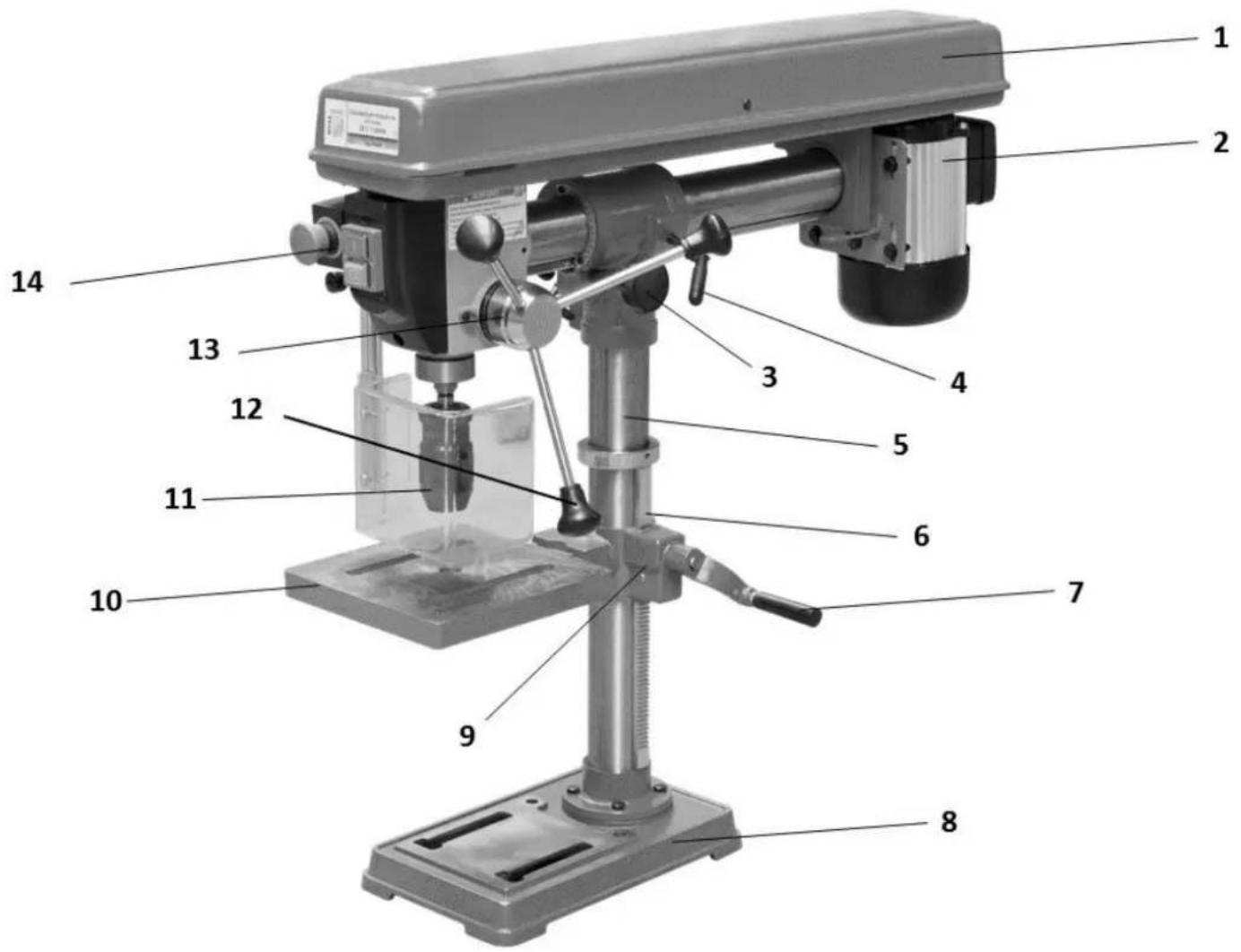
10.1.2 SB 3116RMN
| SB 3116RHN | |||
| 1 | pulley cover | 8 | base |
| 2 | motor | 9 | table bracket |
| 3 | clamping lever for radial adjustment | 10 | table |
| 4 | clamping lever | 11 | drill chuck |
| 5 | column | 12 | feed lever |
| 6 | rack | 13 | scale ring |
| 7 | handle | 14 | On-Off- switch and emergency stop |
10.2 Technical details
| SB 3116RHN | SB 3116RMN | |
| max. drilling capacity | 16mm | 16mm |
| spindle speeds | (5) 500-2500min-1 | (5) 500-2500min-1 |
| voltage | 400V / 230V | 400V / 230V |
| distance spindle to column | 130-420mm | 130-420mm |
| spindle holder | MK2 / MT2 | MK2 / MT2 |
| max. spindle travel | 80mm | 80mm |
| max. distance chuck to table | 740mm | 355mm |
| max. distance chuck to base | 1185mm | 470mm |
| table dimensions | Ø300mm | 220 x 220mm |
| base | 275 x 490mm | 310 x 350mm |
| motor power | S1(100%)/S6 600W/900W | S1(100%)/S6 600W/900W |
| total height | 1640mm | 805mm |
| net weight | 58kg | 40kg |
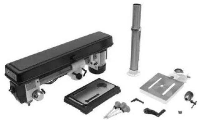
10.3 Delivery content
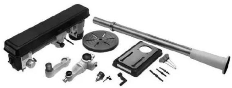
10.3.1 SB 3116RHN
10.3.2 SB 3116RMN
11 SAFETY
11.1 Intended Use
The machine must only be used for its intended purpose! Any other use is deemed to be a case of misuse.
To use the machine properly you must also observe and follow all safety regulations, the assembly instructions, operating and maintenance instructions lay down in this manual.
All people who use and service the machine have to be acquainted with this manual and must be informed about the machine's potential hazards.
It is also imperative to observe the accident prevention regulations in force in your area.
The same applies for the general rules of occupational health and safety.
The machine is used for:
Drilling in wood, plastic and metal.
Any manipulation of the machine or its parts is a misuse, in this case HOLZMANN-MASCHINEN and its sales partners cannot be made liable for ANY direct or indirect damage.
Even when the machine is used as prescribed it is still impossible to eliminate certain residual risk factors.

WARNING
- Use only drills allowable for this machine!
- Never use a damaged drill!
- Use the machine never with defective or without mounted guard!
- The removal or modification of the safety components may result in damage to equipment and serious injury!
HIGHEST RISK OF INJURY!
Ambient conditions
The machine may be operated:
humidity
max. 70%
temperature
+5°C to +40°C (+41°F to +104°F)
The machine must not be operated outdoors or in wet or damp areas.
The machine must not be operated in areas exposed to increased fire or explosion hazard.
Prohibited use
- The operation of the machine outside the stated technical limits described in this manual is forbidden.
Operation of the machine function without emergency stop button or impeller box with open doors is prohibited.
The use of the machine not according with the required dimensions is forbidden. - The use of the machine not being suitable for the use of the machine and not being certified is forbidden.
- Any manipulation of the machine and parts is forbidden.
- The use of the machine for any purposes other than described in this user-manual is forbidden.
The unattended operation on the machine during the working process is forbidden!
It is not allowed to leave the immediate work area during the work is being performed.
11.2 Security instructions
Missing or non-readable security stickers have to be replaced immediately!
The locally applicable laws and regulations may specify the minimum age of the operator and limit the use of this machine!
To avoid malfunction, machine defects and injuries, read the following security instructions!

NOTICE
In the following machine this guards are in effect:
Emergency button on the control panel
- Shutdown when opening the motor pulley cover

- Keep your work area dry and tidy! An untidy work area may cause accidents. Avoid slippery floor.
Make sure the work area is lighted sufficiently
Make sure that the work area is well ventilated - Do not overload the machine
- Provide good stability and keep balance all times
- Avoid abnormal working postures! Make sure you stand squarely and keep balance at all times.
- Keep away from the running drill!
- Always stay focused when working. Reduce distortion sources in your working environment. The operation of the machine when being tired, as well as under the influence of alcohol, drugs or concentration influencing medicaments is forbidden.

- Do not climb onto the machine!
- Attach the machine to the underground
- Respectively trained people only and only one person shall operate the machine.
- Do not allow other people, particularly children, to touch the machine or the cable. Keep them away from your work area.
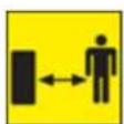
Make your workshop childproof. - Make sure there is nobody present in the dangerous area. The minimum safety distance is 2m


- Wear suitable work clothes! Do not wear loose clothing or jewelry as they might be caught and cause severe accidents!
- Wear a hair net if you have long hair.
-
Loose objects can become entangled and cause serious injuries!
-
Use personal safety equipment: ear protectors and safety goggles when working with the machine.
Operation with gloves forbidden!


- Never leave the machine running unattended! Before leaving the working area switch the machine off and wait until the machine stops.
Always disconnect the machine prior to any actions performed at the machine. - Avoid unintentional starting
- Do not use the machine with damaged switch

- The plug of an electrical tool must strictly correspond to the socket. Do not use any adapters together with earthed electric tools
Each time you work with an electrically operated machine, caution is advised! There is a risk of electric shock, fire, cutting injury; - Protect the machine from dampness (causing a short circuit)
- Use power tools and machines never in the vicinity of flammable liquids and gases (danger of explosion)
- Check the cable regularly for damage
- When working with the machine outdoors, use extension cables suitable for outdoor use
- Do not use the cable to carry the machine or to fix the work piece
- Protect the cable from heat, oil and sharp edges
- Avoid body contact with earthed

- Before starting the machine remove any adjusting wrenches and screwdrivers
- Use a clip or clamping jaws to secure the workpiece
- Do not fix the workpiece with your hands
- Rotating parts can cause severe cut injuries
- Keep the drills sharp and clean, so they get stuck less often and are easier to guide
- Keep any machine that is not being used out of reach of children

NOTICE
Emergency procedure
A first aid kit in accordance with ISO 3864 should always be readily available for a possible accident. Initiate the violation in accordance with the necessary first aid measures. When requesting support, provide the following details:

-
Place of accident
-
Type of accident
-
Number of injured people
-
Injury type(s)
11.3 Remaining risk factors

WARNING
It is important to ensure that each machine has remaining risks. In the execution of all work (even the simplest) greatest attention is required. A safe working depends on you!
Even if the machine is used as required it is still impossible to eliminate certain residual risk factors totally. The following hazards may arise in connection with the machine's construction and design:
Despite of correct and proper use and maintenance there remain some residual risk factors:
- Hazard of injury or machine damage due to undetected machine defect
To minimize this risk, check the machine prior to every operation for loose screws and connections. Check the motor noise, the spindle, the drill chuck, etc. for eventual damage.
Damaged parts have to be replaced immediately, no operation of the machine in the meantime!
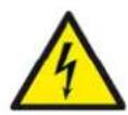
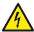
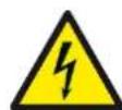
- Hazard of electric shock
Undetected malfunctions in the power supply and/or the connected wood working machine might result in electric shock when touching the machine. Ensure proper electric installation, and let it check periodically by a trained electrician.
- Danger due to unintended machine start-up
Eliminate this risk by disconnecting the machine before you perform any checks or activities on the machine.
- Hazard of inhaling toxic dust
Especially wood dust arising from chemically treated wood and/or lacquer/paint are harmful when inhaled. Therefore wear a suitable breathing mask if required.
These risk factors can be minimized through obeying all security and operation instructions, proper machine maintenance, proficient and appropriate operation by persons with technical knowledge and experience.
12 ASSEMBLY
12.1 Delivery content
Please check the product contents immediately after receipt for any eventual transport damage or missing parts. Claims from transport damage or missing parts must be placed immediately after initial machine receipt and unpacking before putting the machine into operation. Please understand that later claims cannot be accepted anymore.
12.2 Preparatory activities
12.2.1 Workplace requirements
The workplace has to fulfill the requirements.
The ground has to be even, in level and hard. It must be suitable at least to weight it with double weight per square meter than the machines net weight.
The chosen workplace must have access to a suitable electric supply net hat complies with the machines requirements.
12.2.2 Transport
The machine can be transported in package with a forklift.
The machine is very heavy. The machine shall be lifted from crate with a suitable lifting device only that is certified to be able to carry the machines load.

WARNING
The lifting and transportation of the machine must only be carried out by qualified staff and must be carried out with appropriate equipment.
Note that lifting equipment used (crane, forklift, sling, etc.) must be in perfect condition.
To maneuver the machine in the packaging can also a pallet jack or a forklift be used.
12.2.3 Preparation of the surface
Uncoated metal machine parts have been insulated with a greasy layer to inhibit corrosion.
This layer has to be removed. You can use standard solvents that do not damage the machine surface.

NOTICE
Do not use solvents based on nitrite, aggressive solvents like break cleaners or scrubbing agents!
These damage the machine surface.
12.3 Power supply
ATTENTI ON
When working with non-grounded machines:
Severe injury or even death may arise though electrocution!
Therefore: The machine must be operated at a grounded power socket
The connection of the machine to the electric power supply and the following checks have to be carried out by a respectively trained electrician only.
- The electronic connection of the machine is designated for operation with a grounded power socket!
- The connector plug may not be manipulated.
- The mains supply must be secured with 16A:
- If the connector plug doesn't fit or if it is defect, only qualified electricians may modify or re-new it!
- The grounding wire should be held in green-yellow.
- A damaged cable has to be exchanged immediately!
- Check, whether the feeding voltage and the Hz comply to the required values of the machine. A deviation of feeding voltage of ± 5% is allowed (e.g.: a machine with working voltage of 380V can work within a voltage bandwidth of 370 till 400V .
- Make sure that a possible extension cord is in good condition and suitable for the transmission of power. An undersized cord reduces the transmission of power and heats up.
- A damaged cable must be replaced immediately

NOTICE
Operation is only allowed with safety switch against stray current (RCD max. stray current of 30mA)

NOTICE
Use only permitted extension cable with cross-section the one in the following table declared.
| Voltage | Extension | Cross-section |
| 220 V-240 V 50 Hz | <27 m | 1,5 mm² |
| <44 m | 2,5 mm² | |
| <70 m | 4,0 mm² | |
| <105 m | 6,0 mm² | |
| Plug 400V: | 5-wire: with N-conductor | 4-wire: without N-conductor |
12.4 Assembly

To aid in assembly, refer to the upper assembly drawing as well as to the parts drawings at the end of this manual. The machine assembly is shown on basis of the model SB 3116RHN.
- Position the Base (B6) on a level and sturdy floor for mounting. Bolt the Base to the floor using appropriate hardware (not supplied). Base holes will accommodate 7/16 inch bolts. Pull out the Wire Stabilizer (B21) rod from the rear of the Base.
- Place the Column Support (B4) on the Base, aligning the mounting holes.
- Insert four large Hex Screws into the mounting holes and tighten with a wrench.
- Insert the Column (B1) into the Column Support (B4) and secure with Screw,
- Install the Table Support (B7), with attached table Arm, over the Column (B1) and slide it down. Engage the gears onto the Rack. Tighten the Table Clamp.
- Slide the Column Collar (B19) over and down the Column (B1) about 8 inches. Tighten Screw (B11).
- Place the Extend Arm into the Arm, and then the Table (B20) into the opening in the Extend Arm.

WARNING
The next step involves lifting the head assembly onto the Column. The head assembly is heavy. Have someone help you lift this assembly into place!
- Lift the Head Assembly and insert the Column Guide (18) over the Column (B1).
Slide it down on the Column Tube as far as it will go. Align it so that it faces straight forward, in line with the Base.
-
Insert one Locking Shoe (15) into place inside the bottom of the Column Guide (18), and the other on the outside of the Column Guide. Tighten the Clamping Lever (30) into the Locking Shoe at the base of the Column Guide.
-
Locate the Feed Knobs (34) and Feed Rods and screw into the Hub.
-
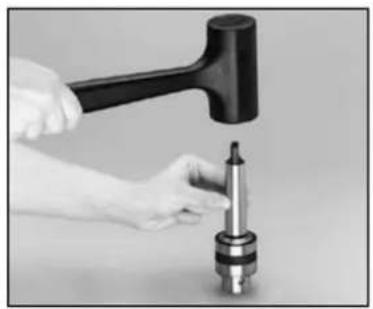
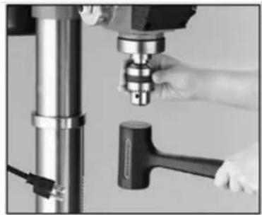
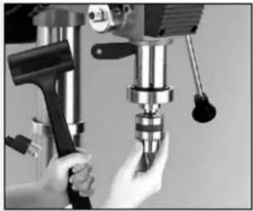
Install the Chuck (A12). Thoroughly clean the tapered hole in the Chuck and the Spindle (A15) shaft of all dirt, grease, oil, and protective coatings (paint thinner may be necessary). Slide the Chuck onto the Spindle shaft. Turn the Chuck sleeve clockwise and open the jaws completely. Tap the nose of the Chuck lightly with a piece of wood to securely set the Chuck.
- Verify that the Table is square (90 degrees) to the Head Assembly and drill bit.
-
Adjust V-Belt tension or change speeds.
-
Open the Belt Guard (A25) to expose the V-Belt.
- Loosen the Thumb Nut (28) to relieve the V-Belt tension.
- Push the Motor backward, tightening the Belt on the pulleys, and hold in place.
- Turn the Thumb Nut (28) clockwise to tighten the V-Belt in place.
- Refer to the chart inside the Guard lid to select speed and belt locations.

WARNING
Overtightening the belts can cause the motor to bind and not start. It can also damage motor bearings!
12.5 Assembly spindle protection

13 OPERATION
Device to be operated in a perfect state only. Inspect the device visually every time it is to be used. Check in particular the safety equipment, electrical controls, electric cables and screwed connection for damage and if tightened properly. Replace any damaged parts before operating the device.
13.1 Operation instructions

WARNING
Perform all machine settings with the machine being disconnected from the power supply!

ATTENTION
Do not attempt to drill material with the surface other than flat unless a suitable support is available!
Never switch the machine on while pressing the drill bit against the material!

NOT ICE
- Before switching the machine on, make sure that the table-clamping lever is firmly tightened
- Make sure that the bit is firmly clamped in the chuck
- Due to the height of its own weight is the fixation of the drill press to the ground requirement for less-vibration work.
- Before switching the machine on, make sure that the chuck key is removed
- Use a clip or clamping jaws to secure the piece to be drilled on the table
- Set the drill to speed answering a specific job
- Check the V-belts and tighten if necessary
- In advanced wear of, replace V-belt
V-belts and pulleys may not come into contact with grease, oil or other lubricants - Loosen the V-belt for a long break
After drilling movement the sleeve up to the highest position to turn back by hand. Not simply leaving out the rotating lever. In order to protect the return spring and a long life. You can modify the tension of the return spring by removing the cover and move the spiral spring. The coil spring is located on the rotary lever, on the opposite side of the machine.
13.2 Operation
With the ON/OFF / EMERGENCY unit, the machine is switched on and off. For this, the EMERGENCY-STOP-cap must be unlocked. Note: Press the switch only after you have chosen the direction of rotation and spindle speed.
13.2.1 Spindle speed
The exact cutting speeds are given in the specifications of the drill manufacturers. Basically the following rule of thumb applies:

NOTICE
As smaller the hole, as higher the rotation speed.
To achieve a good result is also:
- Soft material = > high rotation speed
- Hard material low rotation speed
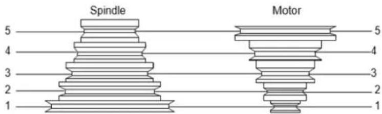
5-5:2500 min
4-4:1900 min
3-3:1300 min
2-2: 800min^-1
1-1: 500min^-1
- Lift the PULLEY COVER.
- Loosen the Thumb Nut. The BELT TENSION should release.
- Move the V-belt to the desired level (speed) on the pulleys.
- Push the Motor backward and hold. Retighten the Thumb Nut.
- Close the Belt PULLEY COVER.
13.2.2 Table
- Loosen the Support Clamp.
- Turn the Crank to move the Table to the desired height.
- Tighten the Support Clamp.
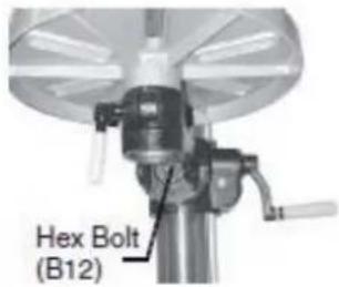
- To tilt the Table, loosen Hex Bolt and turn the Table. The scale can be used to approximate the angle. Tighten the Hex Bolt.
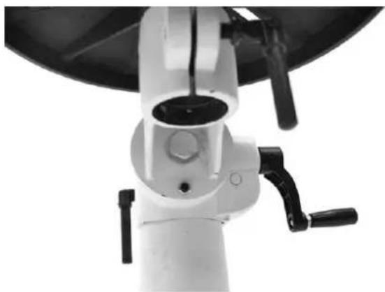
13.2.3 Adjusting head angle
- To adjust the Head angle to other than 90 degrees, loosen the right Clamping Lever.
- Pull out the Guide Pin and turn it 90 degrees so that it's cross pin rests on top of the outlet.
- Align the mark on the Column Guide with the Scale.
- Once the Head is tilted to the desired angle, retighten the Clamping Lever.
- To return the Head to the 90 degree position, do these procedures in reverse.
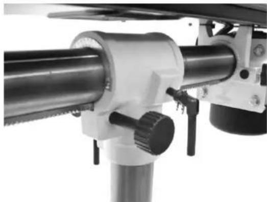
13.2.4 Adjusting head horizontally
- Loosen the right-side Clamping Lever.
- Turn the Moving Bar clockwise or counterclockwise until the desired position is reached.
- Tighten the right-side Clamping Lever.
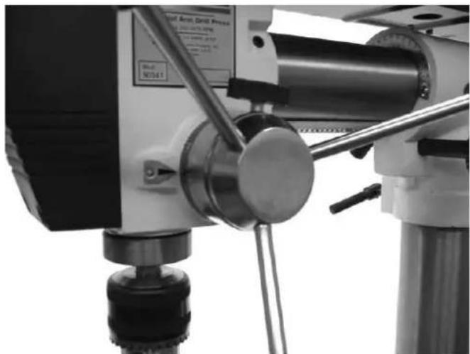
13.2.5 Adjusting specified drill depth
- Secure the workpiece to the Table.
- Mark the desired whole depth on the side of the workpiece. Also view the depth indicator on the Depth Stop Ring.
- Loosen the Depth Lock Screw.
- Turn the scale on the Depth Stop Ring to the desired depth and retighten the Depth Lock Screw.
- Pull the Feed Knob (34) counterclockwise until it drills the hole and stops at the set depth.
14 MAINTENANCE

ATTENTI ON
Don't clean or do maintenance on the machine while it is still connected to the power supply:
Damages to machine and injuries might occur due to unintended switching on of the machine!
Therefore: Switch the machine off and disconnect it from the power supply before any maintenance works or cleaning is carried out
The machine does not require extensive maintenance. If malfunctions and defects occur, let it be serviced by trained persons only.
Before first operation as well as later on every 100 operation hours you should lubricate all connecting parts (if required, remove beforehand with a brush all swarfs and dust).
Check regularly the condition of the security stickers. Replace them if required.
Check regularly the condition of the saw band and the saw band guide.
The good condition and perfect adjustment of the guiding rollers is essential for a smooth band guidance and a clean cut.
Store the machine in a closed, dry location.
NOTICE
Clean your machine regularly after every usage - it prolongs the machines lifespan and is a pre-requisite for a safe working environment.
Repair jobs shall be performed by respectively trained professionals only!
14.1 Maintenance plan
After each workshift:
- Apply a thin layer of oil on the column and the table
- Remove drill cuttings and metal chips from the device
After 50 hours of operation
- Apply some fat on the angle drift
14.2 Cleaning
After each workshift the machine has to be cleaned. Remove chips etc. with a suitable tool. Do not remove them by hand (cutting injury!). Remove dust as well.

NOTICE
The usage of certain solutions containing ingredients damaging metal surfaces as well as the use of scrubbing agents will damage the machine surface!
Clean the machine surface with a wet cloth soaked in a mild solution
14.3 Disposal
Do not dispose the machine in residual waste. Contact your local authorities for information regarding the available disposal options. When you buy at your local dealer for a replacement unit, the latter is obliged to exchange your old.
15 TROUBLE SHOOTING
BEFORE YOU START WORKING FOR THE ELIMINATION OF DEFECTS, DISCONNECT THE MACHINE FROM THE POWER SUPPLY.
| Fehler | Mögliche Ursache | Behebung |
| Motor does not run | ·Incorrect power supply | Let it be checked by a trained person |
| ·Switch defect | Change | |
| ·Motor defect | Change | |
| ·Safety switch activated | Check the cover of motor pulley (open?). | |
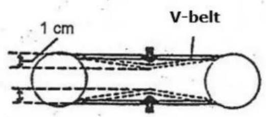
| Loud noise when running | ·Incorrect belt tension | Adjust belt tension (1cm rule) |
| Drill runs erratically | ·Drill chuck not assembled correctly to arbour or one of them is dirty | Check and adjust. |
| ·Drill chuck jaws worn or damaged | Change drill chucj | |
| ·Spindle or boring is worn | Check and replace if neessary | |
| Drill is hot and smokes | ·Too fast speed for material being drilled | Reduce speed use lubricants |
| Motor runs but no rotation or weak drilling power | ·Belt tension too low ·Pulley belt dirty, slippery | Tighten Clean |
MANY POTENTIAL SOURCES OF ERROR CAN BE CLEARED BY THE EXPERTLY CONNECTION TO THE ELECTRICITY GRID.

NOTICE
Should you in necessary repairs not able to properly to perform or you have not the prescribed training for it always attract a workshop to fix the problem.
16 PREFACIO (ES)
Estimado CLIENTE,
Elle fonctionnera比较好, but it's not as good as the others.
UTILISER CORRECTE CABLE DE RALLONGE
HOOGSTE RISICO VAN LETSELS!
Arbeidsvoorwaarden
52.2.3 Forberedelse avytan
With original HOLZMANN spare parts you use parts that are attuned to each other shorten the installation time and elongate your products lifespan.
IMP OR TANT
The installation of other than original spare parts voids the warranty!
So you always have to use original spare parts
When you place a spare parts order please use the service formular you can find in the last chapter of this manual. Always take a note of the machine type, spare parts number and partname. We recommend to copy the spare parts diagram and mark the spare part you need.
You find the order address in the preface of this operation manual.
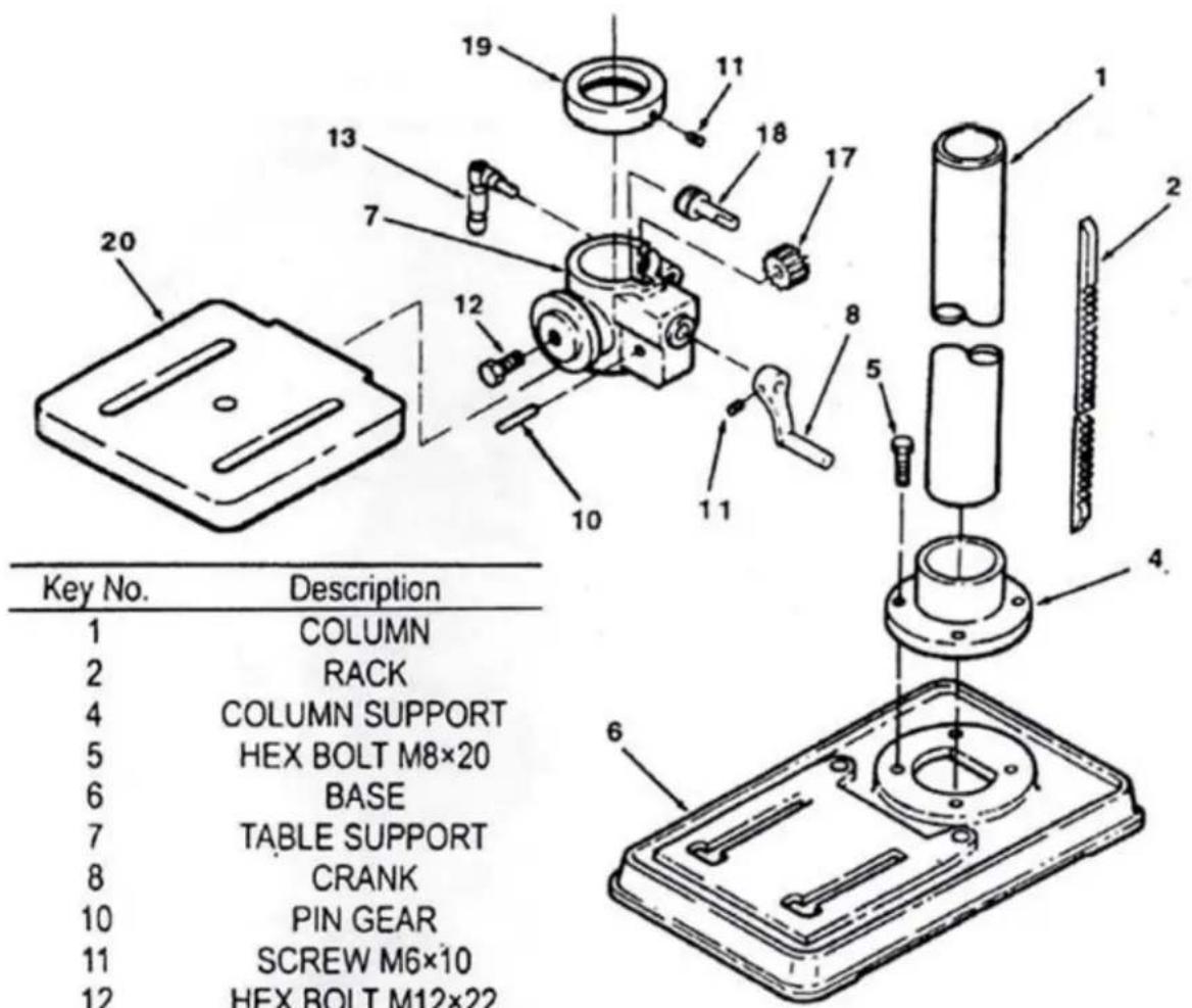
| Item # | Description |
| B1 | Column |
| B2 | Rack |
| B3 | Screw, M10x12 |
| B4 | Column Support |
| B5 | Hex Bolt, M10x40 |
| B6 | Base |
| B7 | Table Support |
| B8 | Crank |
| B10 | Pin Gear |
| B11 | Screw, M6x10 |
| B12 | Hex Bolt, M16x35 |
| B13 | Table Clamp |
| B14 | Arm |
| B15 | Extend Arm |
| B16 | Support Clamp |
| B17 | Gear, Helical |
| B18 | Worm, Elevation |
| B19 | Column Collar |
| B20 | Table |
| B21 | Wire Stabilizer |
SB 3116RMN
58
EG-KONFORMITÄTSERKLÄRUNG/CE-CERTIFICATE OF CONFORMITY
| CE | Inverkehrbringer / Distributor HOLZMANN MASCHINEN® GmbH 4170 Haslach, Marktplatz 4, AUSTRIA Tel.: +43/7289/71562-0; Fax.: +43/7289/71562-4 www.holzmann-maschinen.at |
| Bezeichnung / name | |
| STÄNDERBOHRMASCHINE / DRILL PRESS | |
| Typ / model | |
| SB 3116RHN / SB 3116RMN | |
| EG-Richtlinien / EC-directives | |
| •2006/42/EG; •2014/35/EU, •2014/30/EU | |
| Angewandte Normen / applicable Standards | |
| • ·EN 12717:2001/A1:2009, •EN 60204-4:2006/A1:2009, •EN 55014-1:2006/A2:2011, •EN 55014-2:1997/A2:2008, •EN 61000-3-2:2014, •EN 61000-3-3:2013 | |
Hereby we declare that the above mentioned machines meet the essential safety and health requirements of the above stated EC directives. Any manipulation or change of the machine not being explicitly authorized by us in advance renders this document null and void.
For mechanical and electrical components Company Holzmann Maschinen GmbH garants a warranty period of 2 years for DIY use and a warranty period of 1 year for professional/industrial use - starting with the purchase of the final consumer (invoice date).
In case of defects during this period which are not excluded by paragraph 3, Holzmann will repair or replace the machine at its own discretion.
2.) Report:
In order to check the legitimacy of warranty claims, the final consumer must contact his dealer. The dealer has to report in written form the occurred defect to Holzmann. If the warranty claim is legitimate, Holzmann will pick up the defective machine from the dealer. Returned shipments by dealers which have not been coordinated with Holzmann will not be accepted. A RMA number is an absolute must-have for us - we won't accept returned goods without an RMA number!
3.) Regulations:
a) Warranty claims will only be accepted when a copy of the original invoice or cash voucher from the trading partner of Holzmann is enclosed to the machine. The warranty claim expires if the accessories belonging to the machine are missing.
b) The warranty does not include free checking, maintenance, inspection or service works on the machine. Defects due to incorrect usage through the final consumer or his dealer will not be accepted as warranty claims either.
c) Excluded are defects on wearing parts such as carbon brushes, fangers, knives, rollers, cutting plates, cutting devices, guides, couplings, seals, impellers, blades, hydraulic oils, oil filters, sliding jaws, switches, belts, etc.
d) Also excluded are damages on the machine caused by incorrect or inappropriate usage, if it was used for a purpose which the machine is not supposed to, ignoring the user manual, force majeure, repairs or technical manipulations by not authorized workshops or by the customer himself, usage of non-original Holzmann spare parts or accessories.
e) After inspection by our qualified staff, resulted costs (like freight charges) and expenses for not legitimated warranty claims will be charged to the final customer or dealer.
f) In case of defective machines outside the warranty period, we will only repair after advance payment or dealer's invoice according to the cost estimate (incl. freight costs) of Holzmann.
g) Warranty claims can only be granted for customers of an authorized Holzmann dealer who directly purchased the machine from Holzmann. These claims are not transferable in case of multiple sales of the machine.
4.) Claims for compensation and other liabilities:
The liability of company Holzmann is limited to the value of goods in all cases.
Claims for compensation because of poor performance, lacks, damages or loss of earnings due to defects during the warranty period will not be accepted.
Holzmann insists on its right to subsequent improvement of the machine.
SERVICE
After Guarantee and warranty expiration specialist repair shops can perform maintenance and repair jobs. But we are still at your service as well with spare parts and/or product service. Place your spare part / repair service cost inquiry by filing the SERVICE form on the following page and send it:
via Mail to info@holzmann-maschinen.at
or via Fax to: +43 7289 71562 4
61 GARANTÍA Y SERVICIO
PRODUCT EXPERIENCE FORM
We observe the quality of our delivered products in the frame of a Quality Management policy.
Your opinion is essential for further product development and product choice. Please let us know about your:
- Impressions and suggestions for improvement.
- experiences that may be useful for other users and for product design
- Experiences with malfunctions that occur in specific operation modes
We would like to ask you to note down you experiences and observations and send them to us via FAX, E-Mail or by post:
Erworbenvon/purchasedfrom:
E-Mail/e-mail:
Please describe amongst others in the problem: What has caused the problem/defect, what was the last activity before you noticed the problem/defect?
For electrical problems: Have you had checked you electric supply and the machine already by a certified electrician?
3. Bite beachten
UNVOLLSTÄNDIG AUSGEGÜLLTE FORMULARE KÖNNN NICT HERBEITET WERDEN!
GARANTIEANTRAGE KONNEN AUSSCHLIJESSLICH UTER BEILAGE DES KAUFBELEGES/ABLIEFERBELEGES AKZEPTIERT WERDEN.
Additional information
INCOMPLETELY FILLED SERVICE FORMS CANNOT BE PROCESSED! FOR GUARANTEE CLAIMS PLEASE ADD A COPY OF YOUR ORIGINAL SALES / DELIVERY RECEIPT OTHERWISE IT CANNOT BE ACCEPTED. FOR SPARE PART ORDERS PLEASE ADD TO THIS SERVICE FORM A COPY OF THE RESPECTIVE EXPLODED DRAWING WITH THE REQUIRED SPARE PARTS BEING MARKED CLEARLY AND UNMISTAKABLE.
THIS HELPS US TO IDENTIFY THE REQUIRED SPARE PARTS FASTLY AND ACCELERATES THE HANDLING OF YOUR INQUIRY.