
RWH180ALU - Uncategorized Holzmann - Free user manual and instructions
Find the device manual for free RWH180ALU Holzmann in PDF.


| Product Type | Service Jack |
| Brand | Holzmann |
| Model | RWH180ALU |
| Lifting Capacity | 1800 kg |
| Lift Range | 85 - 470 mm |
| Product Dimensions (L x W x H) | 715 x 295 x 160 mm |
| Packaging Dimensions (L x W x H) | 770 x 360 x 180 mm |
| Net Weight | 19 kg |
| Gross Weight | 21 kg |
| Material | Aluminum construction, chrome roller |
| Handle | Two-sided handle (both sides) |
| Saddle Pad | Professional rubber pad on support plate |
| Quick Lift Function | Twin pump for rapid lifting |
| Valve Control | Corrugated hand lever with cardan joint and securing knurled screw |
| Wheels | Rear casters, sturdy joint roll |
| Hydraulic System | Hydraulic unit with fill and bleed ports |
| Recommended Oil | High-grade hydraulic oil |
| Safety Standards | Meets workshop quality and high-end processing standards |
| Certifications | EC-Conform, compliant with directives |
| Usage | Lifting vehicles; must support with jack stands after lifting |
| Warranty | 12 months (6 months for commercial use) |
Frequently Asked Questions - RWH180ALU Holzmann
User questions about RWH180ALU Holzmann
0 question about this device. Answer the ones you know or ask your own.
Ask a new question about this device
Download the instructions for your Uncategorized in PDF format for free! Find your manual RWH180ALU - Holzmann and take your electronic device back in hand. On this page are published all the documents necessary for the use of your device. RWH180ALU by Holzmann.
USER MANUAL RWH180ALU Holzmann
Read the operation manual carefully before first use!

Technical data subject to changes, errors excepted!
1 INHALT / INDEX
SAFETY GUIDELINES 21
10.2 Proper usage 21
10.3 Incorrect usage 21
10.4 Safety instructions 21
11 ASSEMBLY 23
11.1 Attaching the Handle 23
11.2 Bleeding 23
11.3 Adding Oil (RWH125ALU/RWH180ALU) 23
11.4 Adding Oil (RWH250ALU) 23
11.5 Lifting 23
11.6 Lowering 24
12 Maintenances and servicing 26
13 TROUBLESHOOTING 27
14 Ersatzteile / Spare Parts 28
EN ATTENTION! Ignoring the safety signs and warnings applied on device as well as ignoring the security and operating instructions can cause serious injuries and even lead to death.

EN READ THE MANUAL! Read the user and maintenance manual carefully and get familiar with the controls n order to use the machine correctly and to avoid injuries and machine defects.
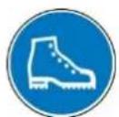

EN PROTECTIVE CLOTHING! The operator is obligated to wear proper protection, safety goggles and safety shoes
EN EC-CONFORM - This product complies with the EC-directives.
3 VORWORT
natural_image
Red mechanical tool with metal components and a labeled 'HOLZMANN-MASCHINEN' on the handle (no other text or symbols visible)natural_image
Red and silver mechanical tool with a handle and wheels (no visible text or symbols)natural_image
Red and silver mechanical lever handle with visible branding (no text or symbols on body)This manual contains Information and important instructions for the installation and correct use of the service jack RWH125ALU/RWH180ALU/RWH250ALU.
This manual is part of the machine and shall not be stored separately from the machine. Save it for later reference and if you let other persons use the machine, add this instruction manual to the machine.

Please read and obey the security instructions!
Before first use read this manual carefully. It eases the correct use of the machine and prevents misunderstanding and damages of machine and the user's health.
Due to constant advancements in product design construction pictures and content may diverse slightly. However, if you discover any errors, inform us please.
Technical specifications are subject to changes!
Please check the product contents immediately after receipt for any eventual transport damage or missing parts. Claims from transport damage or missing parts must be placed immediately after initial machine receipt and unpacking before putting the machine into operation. Please understand that later claims cannot be accepted anymore.
Copyright
© 2014
This document is protected by international copyright law. Any unauthorized duplication, translation or use of pictures, illustrations or text of this manual will be pursued by law – court of jurisdiction is A-4150 Rohrbach, Austria!
CUSTOMER SERVICE CONTACT
easy to move due to aluminium construction
service jack meets high-end processing and high security standards meets workshop quality
handle on both sides (RWH180ALU, RWH 250ALU)
professional rubber pad on support plate
sturdy joint role increase lifespan
well suited for lowered vehicles
corrugated hand lever for closing and opening the
hydraulic valve
power transmission to valve through cardan joint
securing hand lever by flute and knurled screw in the
holding fixture
chrome roller
quick lift function (twin pump)
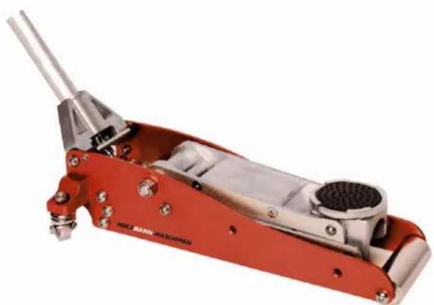
10.1 RWH 125ALU
natural_image
Red mechanical tool with metallic components and a pointed tip, no visible text or symbols| lifting capacity | 1250kg |
| lift range | 85-375mm |
| product dimensions | 580x240x150mm |
| packaging dimension | 610x265x175mm |
| weight (NW/GW) | 12/14kg |
| lifting capacity | 1250kg |
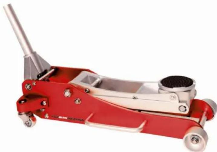
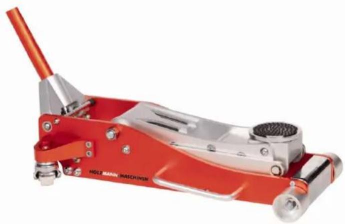
10.1 RWH 180ALU
natural_image
Red and silver mechanical tool with a handle and circular base (no visible text or symbols)| lifting capacity | 1800kg |
| lift range | 85-470mm |
| product dimensions | 715x295x160mm |
| packaging dimension | 770x360x180mm |
| weight (NW/GW) | 19/21kg |
| lifting capacity | 1800kg |
10.1 RWH 250ALU
natural_image
Red and silver mechanical lever handle with visible branding (no text or symbols on the device itself)| lifting capacity | 2500kg |
| lift range | 95-490mm |
| product dimensions | 740x340x170mm |
| packaging dimension | 790x380x200mm |
| weight (NW/GW) | 25/27kg |
| lifting capacity | 2500kg |
SAFETY GUIDELINES
10.2 Proper usage
Holzmann Maschinen cannot be held responsible for any injuries or damages if there was performed manipulation or adjustments to the device.
For another usage and resulting damages or injuries HOLZMANN MASCHINEN doesn't assume any responsibility or guarantees.
10.3 Incorrect usage
Operation of the device that doesn't agree with this manual is forbidden!
• Operation without the safety devices is not allowed.
- You mustn't remove the safety devices!
- Incorrect is the usage for materials which aren't mentioned in this manual.
- Changes of the machine's construction are forbidden.
For another usage and resulting damages or injuries HOLZMANN MASCHINEN doesn't assume any responsibility or guarantees.
10.4 Safety instructions
Warning labels and/or other labels on the machine must be replaced when they were removed.
 | Do not operate the machine at insufficient lighting conditions.Do not operate the machine when you are tired, when your concentration is impaired, and/ or under the influence of drugs, medication or alcohol. |
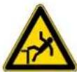 | Climbing onto the machine is forbidden! Heavy injuries by falling down or by tilting of the machine are possible. |
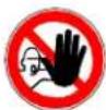 | The machine shall be used only by trained persons.Non authorized persons, especially children, shall be kept away from the work area. |
   | Do not wear loose clothing, long hair openly or loose jewellery like neck laces etc. when operating the machineThey might be caught by rotating parts and cause serious injuries. |
 | Use proper safety clothing and devices when operating the machine (, safety goggles, ear protectors, safety shoes ...)! Do not wear safety gloves for operating because they decrease the working accuracy and they might be pulled into the saw blade. |
WARNING Read all safety warnings and instructions. Failure to heed these markings may result in personal injury and/or property damage.
- Study, understand, and follow all instructions before operating this device.
- Do not exceed rated capacity.
- Use only on hard, level surfaces.
- Lifting device only. Immediately after lifting, support the vehicle with appropriate means.
- Do not move or dolly the vehicle while on the jack.
- Failure to heed these markings may result in personal injury and/or property damage.
- Lift only areas of the vehicle as specified by the vehicle manufacturer.
- No alterations shall be made to this product.
-
Never work on, under or around a load supported only by this device.
-
Do not adjust safety valve.
-
Wear ANSI-approved safety goggles and heavy-duty work gloves during use.
-
Keep clear of load while lifting and lowering.
-
Lower load slowly.
-
Apply parking brake and chock tires before lifting vehicle.
-
Lift vehicle only at manufacturer recommended locations.
-
Inspect before every use; do not use if parts are loose or damaged.
-
Do not use for aircraft purposes.
-
The warnings, precautions, and instructions discussed in this manual cannot cover all possible conditions and situations that may occur. The operator must understand that common sense and caution are factors, which cannot be built into this product, but must be supplied by the operator.
-
The brass components of this product contain lead, a chemical known to the State of California to cause cancer, birth defects (or other reproductive harm). (California Health & Safety code § 25249.5, et seq.)
Important! Before first use:
Check hydraulic oil level and fill to 1/4" below the fill port as needed as stated on page 23. Thoroughly test the Jack for proper operation. If it does not work properly, bleed air from its hydraulic system as stated on page 23.
11 ASSEMBLY
11.1 Attaching the Handle
- Fasten the Upper Handle to the Lower Handle.
- Loosen the Set Screw and insert the assembled Handle into the Handle Socket.
- Tighten the Set Screw.
11.2 Bleeding
- Loosen the Fill Screw (Fig. 1).
- Insert the assembled Handle into the Handle Socket to operate the Release Valve.
- Turn the Handle counterclockwise to open valve.
- Pump the Handle up and down quickly for several times to purge the air from the system.
- Tighten the Fill Screw (Fig. 1).
11.3 Adding Oil (RWH125ALU/RWH180ALU)
- Remove Fill Screw and Screw simultaneously (Fig.1).
- Add qualified hydraulic oil of high grade into the Fill Screw slowly until the oil reaches the top of the oil fill hole.
Note: Do not touch the assembled Handle when adding the hydraulic oil. - Replace the Fill Screw and Screw.
11.4 Adding Oil (RWH250ALU)
- Remove Fill Screw.
- Add qualified hydraulic oil of high grade into the Fill Screw slowly until the oil reaches the top of the oil fill hole.
Note: Do not touch the assembled Handle when adding the hydraulic oil. - Replace the Fill Screw.
11.5 Lifting
WARNING:
- Park vehicle on a flat, level, solid, surface safely away from oncoming traffic. Turn off the vehicle's engine. Place the vehicle's transmission in "PARK" (if automatic) or in its lowest gear (if manual). Set the vehicle's emergency brake. Then, chock the wheels that are not being lifted.
- Turn the Handle counterclockwise to lower the Jack. Once the Jack is fully lowered, turn the Handle firmly clockwise to close it.
- Carefully position the Saddle of the Jack (Fig. 1) under the vehicle manufacturer's recommended lifting point.(See vehicle manufacturer's owner's manual for location of frame lifting point when lifting only one wheel and frame lifting points when lifting the entire front or rear end of the vehicle.)
- Pump the Handle until the top of the Jack's Saddle has nearly reached the vehicle lifting point.
Note: The Jack should be positioned at 90° to the vehicle's lifting point to ensure the Jack's Saddle and vehicle lifting point are in alignment. If not, reposition the Jack before lifting the vehicle.
-
To lift the vehicle, pump the Handle of the Jack. Use smooth, full strokes for best results.
-
Once the vehicle is raised, slide a jack stand of appropriate capacity (not included) under the proper lifting point referred to in the vehicle owner's manual. Always use two jack stands, position them at the same point on each side of the vehicle.
WARNING:
The rated capacity of jack stands is per pair, not the individual capacities combined unless specifically noted on the product by the jack stand manufacturer. Do not exceed rated jack stand capacity. Ensure that the vehicle support points are fully captured between the outer lugs of both jack stands. Use a matched pair of jack stands per vehicle to support one end only. Use 1 pair per vehicle only. Failure to do so may result in sudden loss of load, which may cause personal injury and/or property damage.
- Center the vehicle's lifting point(s) on the saddle of the jack stand(s). Set the jack stand(s) according to the manufacturer's instructions, making sure that they lock securely into position. Note: Always set both Jack Stands at the same height.
- Slowly turn the Handle counterclockwise to lower the vehicle onto the saddle(s) of the jack stand(s). Then, turn the Handle firmly clockwise to close it
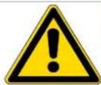
WARNING
When working under the vehicle, this must always be secured with safety stands against unintentional lowering!
11.6 Lowering
- Carefully remove all tools, parts, etc. from under the vehicle.
- Position the Saddle under the lifting point. Turn the Handle firmly clockwise and raise load high enough to clear the jack stands, then carefully remove jack stands.
- Slowly turn the Handle counterclockwise (never more than 1/2 full turn) to lower the vehicle onto the ground.
- Lower the Jack completely. Then, store in a safe, dry location out of reach of children.
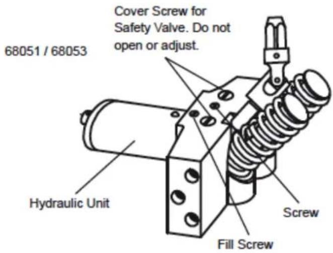
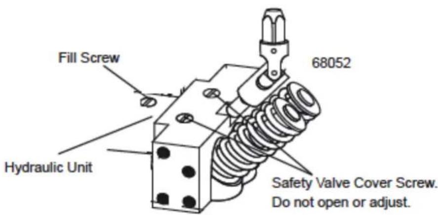
Fig. 1
12 MAINTENANCES AND SERVICING
Procedures not specifically explained in this manual must be performed only by a qualified technician.
To prevent serious injury from tool failure: Do not use damaged equipment. If abnormal noise or vibration occurs, have the problem corrected before further use.
1.1.1 Before each use, inspect the general condition of the Jack. Check for broken, cracked, or bent parts, loose or missing parts, and any condition that may affect the proper operation of the product. If a problem occurs, have the problem corrected before further use. Do not use damaged equipment.
11.2 Before each use, thoroughly test the Jack for proper operation prior to its actual use. If the Jack appears not to be working properly, follow Bleeding instructions on page 2.
11.3 Change the hydraulic oil at least once every three years:
- With the Jack fully lowered, remove the Oil Filler Plug on the side of the Housing.
- Tip the Jack to allow the old hydraulic oil to drain out of the Housing completely, and dispose of the old hydraulic oil in accordance with local regulations.
- With the Jack upright, completely fill the Housing with a high quality hydraulic oil (not included) until the oil is 1/4" below the fill hole.
- Open the valve by turning the Handle counterclockwise and pump the Handle to bleed air from the system.
- Recheck oil level and re-fill as needed.
- Reinstall the Oil Filler Plug.
11.4 Wipe dry with a clean cloth. Then, store the Jack in a safe, dry location out of reach of children and other non-authorized people.
13 TROUBLESHOOTING
To Prevent Serious Injury:
Use caution when troubleshooting a malfunctioning jack. Stay well clear of the supported load. Completely resolve all problems before use. If the solutions presented in the Troubleshooting guide do not solve the problem, have a qualified technician inspect and repair the jack before use.
After the jack is repaired: Test it carefully without a load by raising and lowering it fully, checking for proper operation, BEFORE RETURNING THE JACK TO OPERATION.
DO NOT USE A DAMAGED OR MALFUNCTIONING JACK!
| POSSIBLE SYMPTOMS | PROBABLE SOLUTION(Make certain that the jack is not supporting a load while attempting a solution.) | |||||
| Jack will not lift at its weight capacity | Saddle lowers under load | Pump stroke feels spongy | Saddle will not lift all the way | Handle moves up when jack is under load | Oil leaking from filler plug | |
| X | X | Check that Release Valve is fully closed.Bleed air from the system. | ||||
| X | X | X | Valves may be blocked and may not close fully. To flush the valves:1. Lower the Saddle and securely close the Release Valve.2. Manually lift the saddle several inches.3. Open the release valve and force the saddle down as quickly as possible. | |||
| X | X | X | Jack may be low on oil. Check the oil level and refill if needed. | |||
| Jack may require bleeding - see instructions on page 2. | ||||||
| X | Unit may have too much hydraulic oil inside, check fluid level and adjust if needed. | |||||
14 ERSATZTEILE / SPARE PARTS
RWH125ALU
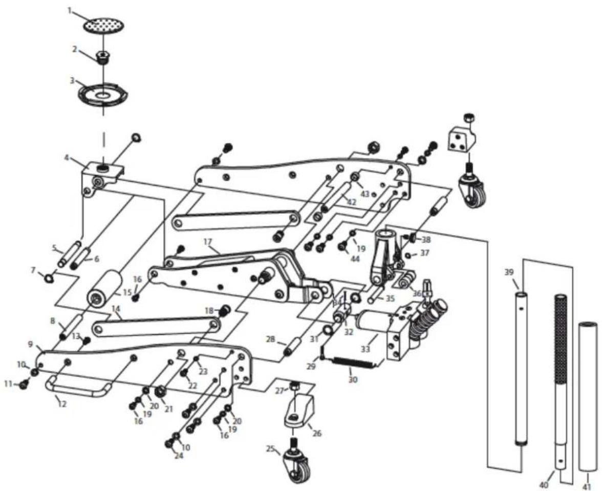
| Part | Description | Qty |
| 1 | Saddle Pad | 1 |
| 2 | Saddle Screw | 1 |
| 3 | Saddle | 1 |
| 4 | Saddle Base | 1 |
| 5 | Shaft | 1 |
| 6 | Shaft | 1 |
| 7 | Retaining Ring (13) | 2 |
| 8 | Front Wheel Axle | 1 |
| 9 | Side Plate | 2 |
| 10 | Washer (M10) | 8 |
| 11 | Screw (M10X20) | 2 |
| 12 | Carrying Handle | 1 |
| 13 | Screw (M6X20) | 2 |
| 14 | Radius Linkage | 2 |
| 15 | Front Wheel | 1 |
| Part | Description | Qty |
| 16 | Screw (M8X16) | 6 |
| 17 | Lift Arm | 1 |
| 18 | Bolt | 2 |
| 19 | Washer (M8) | 10 |
| 20 | Washer (M8) | 4 |
| 21 | Nut (M16) | 2 |
| 22 | Screw (M6X20) | 2 |
| 23 | Washer (M6) | 2 |
| 24 | Screw (M10X25) | 6 |
| 25 | Rear Caster | 2 |
| 26 | Rear Caster Base | 2 |
| 27 | Nut (M10) | 2 |
| 28 | Handle Yoke Shaft | 2 |
| 29 | Clip | 2 |
| 30 | Spring | 2 |
| Part | Description | Qty |
| 31 | Retaining Ring (19) | 2 |
| 32 | Power Unit Adaptor | 1 |
| 33 | Hydraulic Unit | 1 |
| 34 | Pin (M4X26) | 1 |
| 35 | Yoke Roller Shaft | 1 |
| 36 | Yoke Roller | 1 |
| 37 | Retaining Ring (12) | 1 |
| 38 | Set Screw | 1 |
| 39 | Lower Handle | 1 |
| 40 | Upper Handle | 1 |
| 41 | Handle Bumper | 1 |
| 42 | Tie Rod | 1 |
| 43 | Gasket | 2 |
| 44 | Screw (M8X20) | 6 |
RWH180ALU
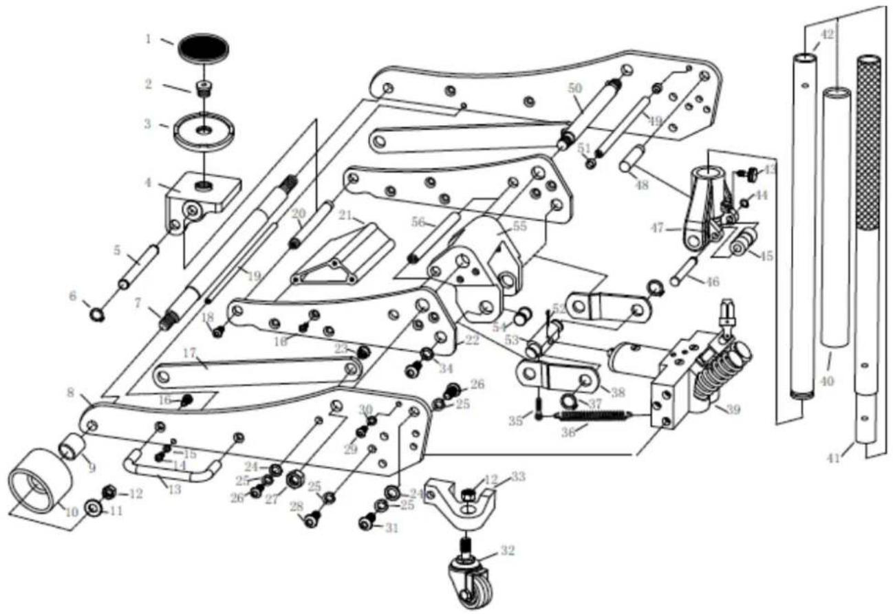
| Part | Description | Qty |
| 1 | Saddle Pad | 1 |
| 2 | Saddle Screw | 1 |
| 3 | Saddle | 1 |
| 4 | Saddle Base | 1 |
| 5 | Shaft | 1 |
| 6 | Retaining Ring (18) | 2 |
| 7 | Front Wheel Axle | 1 |
| 8 | Side Plate | 1 |
| 9 | Bushing | 2 |
| 10 | Front Wheel | 2 |
| 11 | Washer | 2 |
| 12 | Nut (M12) | 4 |
| 13 | Carrying Handle | 2 |
| 14 | Screw (M6X25) | 2 |
| 15 | Washer 6 | 2 |
| 16 | Screw (M8X25) | 14 |
| 17 | Radius Linkage | 2 |
| 18 | Screw | 2 |
| 19 | Tie Rod | 1 |
| Part | Description | Qty |
| 20 | Saddle Shaft | 1 |
| 21 | Tie Block | 1 |
| 22 | Lift Arm Side Plate | 2 |
| 23 | Bolt | 2 |
| 24 | Washer (10) | 2 |
| 25 | Washer (10) | 12 |
| 26 | Screw (M10X25) | 8 |
| 27 | Nut M18 | 2 |
| 28 | Screw (M10X35) | 6 |
| 29 | Screw (M8X20) | 2 |
| 30 | Washer (8) | 2 |
| 31 | Screw (M10X20) | 2 |
| 32 | Rear Caster | 2 |
| 33 | Rear Caster Base | 2 |
| 34 | Washer (10) | 2 |
| 35 | Screw (M6X25) | 2 |
| 36 | Spring | 2 |
| 37 | Retaining Ring (19) | 2 |
| 38 | Short Linkage | 2 |
| Part | Description | Qty |
| 39 | Hydraulic Unit | 1 |
| 40 | Handle Bumper | 1 |
| 41 | Upper Handle | 1 |
| 42 | Lower Handle | 1 |
| 43 | Set Screw | 1 |
| 44 | Retaining Ring (12) | 1 |
| 45 | Socket Roller | 1 |
| 46 | Socket Roller Shaft | 1 |
| 47 | Handle Socket | 1 |
| 48 | Bolt | 2 |
| 49 | Tie Rod | 1 |
| 50 | Lift Arm Shaft | 1 |
| 51 | Rubber Bumper | 2 |
| 52 | Pin (4X45) | 1 |
| 53 | Hydraulic Adaptor | 1 |
| 54 | Bolt | 2 |
| 55 | Block | 1 |
| 56 | Block Shaft | 1 |
RWH250ALU
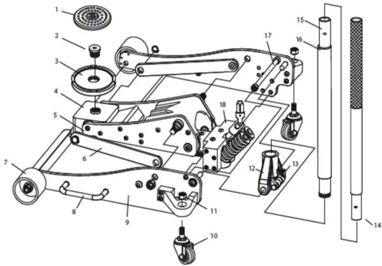
| Part | Description | Qty |
| 1 | Saddle Pad | 1 |
| 2 | Saddle Screw | 1 |
| 3 | Saddle | 1 |
| 4 | Saddle Base | 1 |
| 5 | Lift Arm | 1 |
| 6 | Radius Linkage | 2 |
| 7 | Front Wheel | 2 |
| 8 | Carrying Handle | 2 |
| 9 | Side Plate | 2 |
| Part | Description | Qty |
| 10 | Rear Caster | 2 |
| 11 | Nut (M12) | 4 |
| 12 | Handle Socket | 1 |
| 13 | Set Screw | 1 |
| 14 | Upper Handle | 1 |
| 15 | Lower Handle | 1 |
| 16 | Handle Bumper | 1 |
| 17 | Tie Rod | 1 |
| 18 | Hydraulic Unit | 1 |
14.2 Spare part order
With original Holzmann spare parts you use parts that are attuned to each other and shorten the installation time and elongate your machines lifespan.
I MP OR T AN T
The installation of non-original parts renders warranty null and void.
So you always have to use original spare parts.
You find the order address in the preface of this operation manual.
15 KONFORMITÄTSERKLÄRUNG / CERTIFICATE OF CONFORMITY

E G - KONFOR M I TÄTSE RKLÄR U NG
Hereby we declare that the mentioned machine fulfil the above stated EEC-Directives. Any manipulation of the machines not authorized by HOLZMANN Maschinen renders this document invalid.
(applicable from 11.03.2014)
Please consult our troubleshooting section for initial problem solving. Feel free to contact your HOLZMANN reseller or us for Customer Support!
Warranty claims based on your sales contract with your HOLZMANN retailer, including your statutory rights, shall not be affected by this guarantee declaration. HOLZMANN-MASCHINEN grants guarantee according to following conditions:
A) The guarantee covers the correction of deficiencies to the tool/machine, at no charge, if it can be verified adequately that the deficiencies were caused by a material or manufacturing fault.
B) The guarantee period lasts 12 months, and is reduced to 6 months for tools in commercial use. The guarantee period begins from the time the new tool is purchased from the first end user. The starting date is the date on the original delivery receipt, or the sales receipt in the case of pickup by the customer.
C) Please lodge your guarantee claims to your HOLZMANN reseller you acquired the claimed tool from with following information:
Original Sales receipt and/or delivery receipt
Service form (see next page) filed, with a sufficient deficiency report
for spare part claims: a copy of the respective exploded drawing with the required spare parts being marked clear and unmistakable.
D) The Guarantee handling procedure and place of fulfillment is determined according to HOLZMANNs sole discretion in accordance with the HOLZMANN retail partner. If there is no additional Service contract made including on-site service, the place of fulfillment is principally the HOLZMANN Service Center in Haslach, Austria.
E) Transport charges for sendings to and from our Service Center are not covered in this guarantee. The Guarantee does not cover:
- Wear and tear parts like belts, provided tools etc., except to initial damage which has to be claimed immediately after receipt and initial check of the machine.
- Defects in the tool caused by non-compliance with the operating instructions, improper assembly, insufficient power supply, improper use, abnormal environmental conditions, inappropriate operating conditions, overload or insufficient servicing or maintenance.
- Damages being the causal effect of performed manipulations, changes, additions made to the machine.
- Defects caused by using accessories, components or spare parts other than original HOLZMANN spare parts.
- Slight deviations from the specified quality or slight appearance changes that do not affect functionality or value of the tool.
- Defects resulting from a commercial use of tools that - based on their construction and power output - are not designed and built to be used within the frame of industrial/commercial continuous load.
F) Claims other than the right to correction of faults in the tool named in these guarantee conditions are not covered by our guarantee.
G) This guarantee is voluntary. Therefore Services provided under guarantee do not lengthen or renew the guarantee period for the tool or the replaced part.
SERVICE
After Guarantee and warranty expiration specialist repair shops can perform maintenance and repair jobs. But we are still at your service as well with spare parts and/or machine service. Place your spare part / repair service cost inquiry by filing the SERVICE form on the following page and send it:
via Mail to info@holzmann-maschinen.at
or via Fax to: +43 7248 61 116-421
SERVICE FORM / SERVICEFORMULAR
International numbers with country code
Fax
2. Tool information / Geräteinformationen
serial number/Seriennummer: ____ *Machine type/Maschinentype: ____
Please describe amongst others in the problem:
What has caused the problem/defect, what was the last activity before you noticed the problem/defect?
For electric problems: Have you had checked your electric supply and the machine already by a certified electrician?
3. Additional information
INCOMPLETELY FILED SERVICE FORMS CANNOT BE PROCESSED! FOR GUARANTEE CLAIMS PLEASE ADD A COPY OF YOUR ORIGINAL SALES / DELIVERY RECEIPT OTHERWISE IT CANNOT BE ACCEPTED. FOR SPARE PART ORDERS PLEASE ADD TO THIS SERVICE FORM A COPY OF THE RESPECTIVE EXPLODED DRAWING WITH THE REQUIRED SPARE PARTS BEING MARKED CLEARLY AND UNMISTAKABLE. THIS HELPS US TO IDENTIFY THE REQUIRED SPARE PARTS FASTLY AND ACCELERATES THE HANDLING OF YOUR INQUIRY.
Product experience form
We observe the quality of our delivered products in the frame of a Quality Management policy.
Your opinion is essential for further product development and product choice. Please let us know about your:
- Impressions and suggestions for improvement.
- experiences that may be useful for other users and for product design
- Experiences with malfunctions that occur in specific operation modes
We would like to ask you to note down your experiences and observations and send them to us via FAX, E-Mail or by post:
Thank you for your kind cooperation!
KONTAKTADRESSE / CONTACTS:
- INHALT / INDEX
- VORWORT
- Please read and obey the security instructions!
- Copyright
- CUSTOMER SERVICE CONTACT
- RWH 125ALU
- RWH 180ALU
- RWH 250ALU
- SAFETY GUIDELINES
- Proper usage
- Incorrect usage
- Safety instructions
- Important! Before first use:
- ASSEMBLY
- Attaching the Handle
- Bleeding
- Adding Oil (RWH125ALU/RWH180ALU)
- Adding Oil (RWH250ALU)
- Lifting
- WARNING:
- WARNING
- When working under the vehicle, this must always be secured with safety stands against unintentional lowering!
- Lowering
- MAINTENANCES AND SERVICING
- TROUBLESHOOTING
- To Prevent Serious Injury:
- ERSATZTEILE / SPARE PARTS
- RWH250ALU
- Spare part order
- I MP OR T AN T
- KONFORMITÄTSERKLÄRUNG / CERTIFICATE OF CONFORMITY
- E G - KONFOR M I TÄTSE RKLÄR U NG
- (applicable from 11.03.2014)
- SERVICE
- SERVICE FORM / SERVICEFORMULAR
- Tool information / Geräteinformationen
- Additional information
- Product experience form
Brand : Holzmann
Model : RWH180ALU
Category : Uncategorized