
7104L - Milling machine MAKITA - Free user manual and instructions
Find the device manual for free 7104L MAKITA in PDF.

User questions about 7104L MAKITA
0 question about this device. Answer the ones you know or ask your own.
Ask a new question about this device
Download the instructions for your Milling machine in PDF format for free! Find your manual 7104L - MAKITA and take your electronic device back in hand. On this page are published all the documents necessary for the use of your device. 7104L by MAKITA.
USER MANUAL 7104L MAKITA
GB Chain Mortiser Instruction manual
natural_image
Technical line drawing of a mechanical device with spring and lever mechanism (no text or symbols)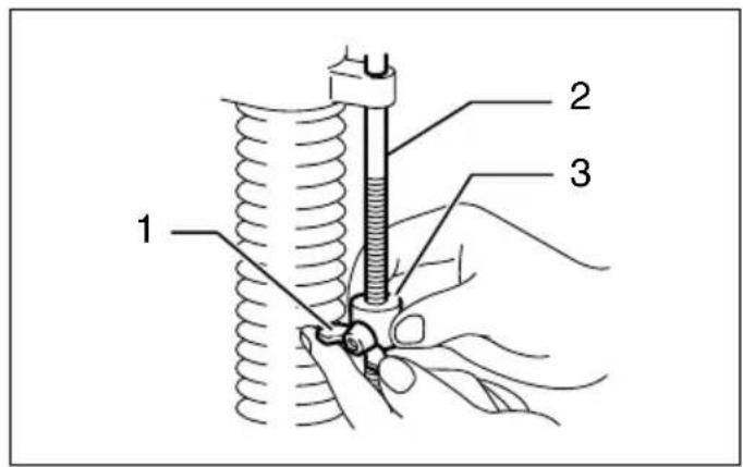
1
2
3
4
5
6
7
8
9
10
11 12
m = 311
13 14
-
natural_image
Line drawing of a mechanical device with hands operating it, no text or symbols present15 16
[Non-Text]
17
ENGLISH (Original instructions)
Explanation of general view
| 1. Wing bolt | 14. Rear vise | 27. Adjusting hex bolt for No. 1 set position |
| 2. Stopper pole | 15. Setting handle | |
| 3. Stopper | 16. Front vise | 28. Adjusting hex bolt for No. 2 set position |
| 4. Lock-off button | 17. Indicator plate | |
| 5. Switch trigger | 18. Indication plate | 29. Original position |
| 6. Adjusting screw | 19. Cutting line (A) | 30. No.1 set position |
| 7. Chain bar | 20. Cutting line (B) | 31. No.2 set position |
| 8. Chain cover | 21. Hook | 32. Ruler |
| 9. Hex bolt | 22. Hex bolts | 33. Front vise |
| 10. Arrow | 23. Gauge plate | 34. Limit mark |
| 11. Sprocket | 24. Travel distance (D) | 35. Brush holder cap |
| 12. Lever (A) | 25. Lever (B) | 36. Screwdriver |
| 13. Vise lever | 26. Lever (C) |
SPECIFICATIONS
| Model 7104L | ||
| Capacities | Max. hole length (Longitudinal) | 130 mm |
| Max. hole depth 155 mm | ||
| Width of applicable workpiece 80 mm – 308 mm | ||
| Chain speed 300 m/min | ||
| Dimensions (L × W × H) | 512 mm × 298 mm × 513 mm | |
| Net weight | 17.3 kg | |
| Safety class | Class I | |
- Due to our continuing programme of research and development, the specifications herein are subject to change without notice.
- Specifications may differ from country to country.
• Weight according to EPTA-Procedure 01/2003
Intended use
ENE062-1
The tool is intended for cutting mortise in wood.
Power supply
ENF001-1
The tool should be connected only to a power supply of the same voltage as indicated on the nameplate, and can only be operated on single-phase AC supply. This tool should be grounded while in use to protect the operator from electric shock. Use only three-wire extension cords which have three-prong grounding-type plugs and three-pole receptacles which accept the tool's plug.
General Power Tool Safety Warnings GEA010-1

WARNING Read all safety warnings and all
instructions. Failure to follow the warnings and instructions may result in electric shock, fire and/or serious injury.
Save all warnings and instructions for future reference.
ADDITIONAL SAFETY RULES
ENB093-1
-
Use this tool only to cut holes in wood.
-
This tool is for cutting holes in flat-surfaced wood. Never use it for cutting holes in a log.
- Wear ear protectors.
- Handle the cutter chain carefully; it is very sharp.
- Place the workpiece on wood blocks or short beams to prevent the cutter chain from hitting the ground, floor, etc., causing damage to the cutter chain at the time of hole breakthrough.
- Check the cutter chain carefully for cracks or damage before operation. Replace cracked or damaged cutter chain immediately.
- Secure the tool to the workpiece firmly.
- Inspect for and remove nails or foreign matter from the workpiece before operation.
- Do not operate the tool with the safety cover open.
- Do not wear gloves during operation.
- Keep hands away from moving parts.
- Remove the tool from the workpiece after operation to keep it from falling off and possibly causing injury.
- Don't abuse cord. Never yank cord to disconnect it from the receptacle. Keep cord away from heat, oil, water and sharp edges.
-
PROPER GROUNDING. This tool should be grounding while in use to protect the operator from electric shock.
-
EXTENSION CORDS. Use only three-wire extension cords which have three-prong grounding-type plugs and three-pole receptacles which accept the tool's plug. Replace or repair damaged or worn cord immediately.
SAVE THESE INSTRUCTIONS.
FUNCTIONAL DESCRIPTION
CAUTION:
• Always be sure that the tool is switched off and unplugged before adjusting or checking function on the tool.
Adjusting depth of cut (Fig. 1)
Loosen the wing bolt on the stopper. Move the stopper to the desired position and tighten the wing bolt. When tightened, the tip of the wing bolts should contact the flat surface of the stopper pole. The numbers indicated on the stopper pole are in cm units (3 mm per graduation).
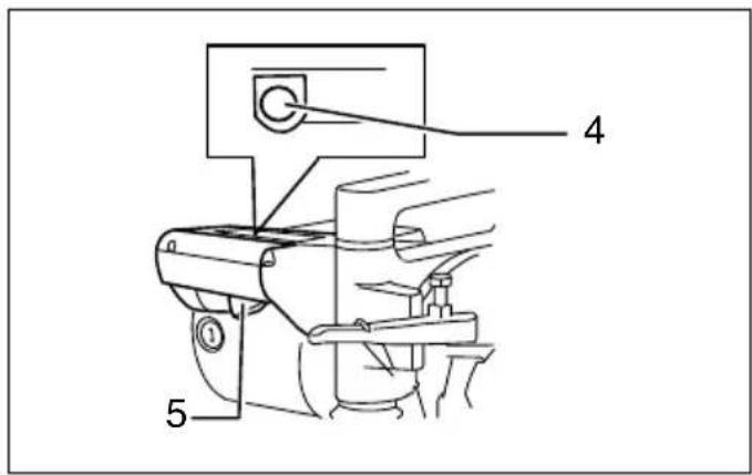
Switch action (Fig. 2)
CAUTION:
- Before plugging in the tool, always check to see that the switch trigger actuates properly and returns to the "OFF" position when released.
To prevent the switch trigger from being accidentally pulled, a lock-off button is provided. To start the tool, push in the lock-off button and pull the switch trigger. Release the switch trigger to stop.
ASSEMBLY
CAUTION:
• Always be sure that the tool is switched off and unplugged before carrying out any work on the tool.
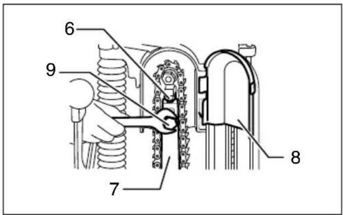
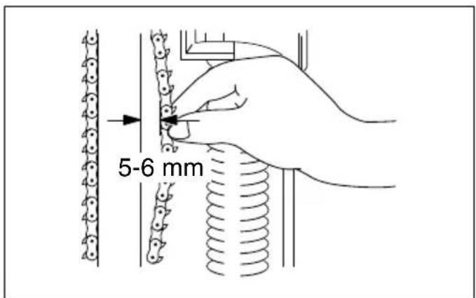
Installing or removing cutter chain (Fig. 3)
WARNING:
- Always be sure that the tool is switched off and unplugged before installing or removing the cutter chain.
- Always close the chain cover after installing, removing or adjusting the cutter chain.
To install the cutter chain, open the chain cover. Loosen the hex bolt securing the chain bar and the adjusting screw.
Orient the cutters in the direction of the arrow on the tool (rotational direction). Attach the cutter chain to the sprocket first and then to the chain bar. Semitighten the hex bolt. (Fig. 4)
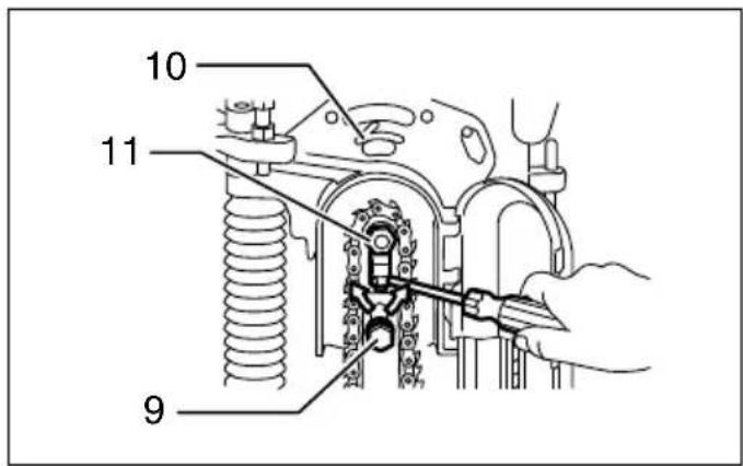
Turn the adjusting screw to increase the tension on the cutter chain. Pull the middle of the cutter chain lightly. When there is a clearance of approx. 5 – 6 mm between the chain bar and the cutter chain, the tension on the cutter chain is adequate. (Fig. 5)
After adjusting the tension, tighten the hex bolt firmly to secure the chain bar. Additionally tighten slightly the adjusting screw. Close the chain cover.
To remove the cutter chain, follow the installation procedures in reverse.
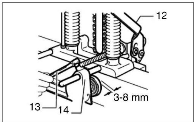
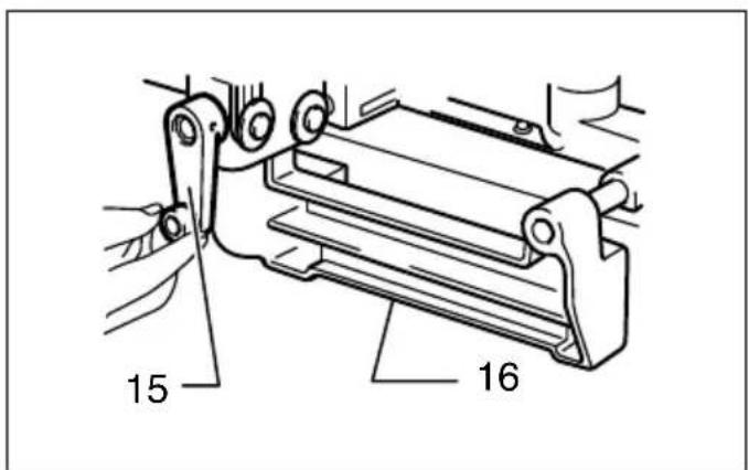
Securing tool to workpiece (Fig. 6 & 7)
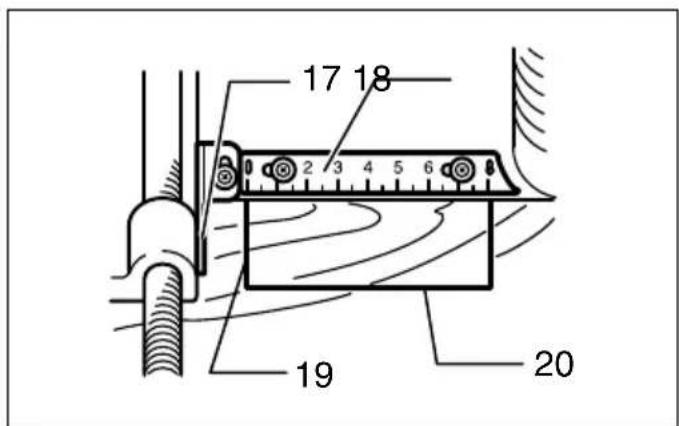
Loosen the vise lever and move the rear vise backward. Place the tool on the workpiece so that the front vise contacts the side of the workpiece. Move the rear vise forward until the distance between the rear vise and the workpiece is 3 – 8 mm. Tighten the vise lever to secure the rear vise. Move the tool so that the "0" on the indication plate is aligned with the cutting line (A). Push the lever (A) down fully to secure the workpiece. Turn the setting handle until the front edge of the yellow indicator plate is aligned with the cutting line (B). (Fig. 8)
OPERATION (Fig. 9)
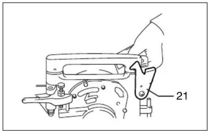
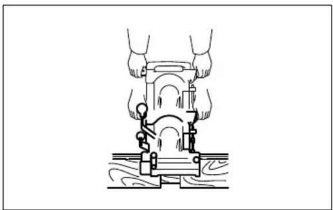
Grasp firmly the grips on either side. Switch on the tool and wait until the cutter chain attains full speed. Then release the hook and lower the tool head to cut in the workpiece. Do not apply excessive pressure to the tool. This may not only decrease the working efficiency but also cause a dangerous reaction. Feed slowly at the beginning of a cutting operation, at the time of hole breakthrough and when cutting a knot in the workpiece. After cutting, gently raise the tool head until you can hook the tool head back onto the hook. Then switch off the tool. Raise the lever (A) and remove the tool from the workpiece.
WARNING:
- Always hook the tool head back onto the hook when not operating the tool.
- Never attempt to cut a twisted or warped workpiece which the tool is not secured firmly to.
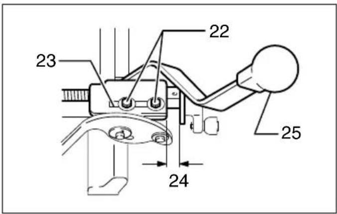
Adjusting indicator plate and indication plate
The yellow indicator plate and indication plate are factory adjusted for the standard equipped cutter chain 16.5 mm. If the alignment is off, for some reason, or when using another size cutter chain, loosen the screws and adjust the yellow indicator plate and indication plate.
Enlarging hole
1. Transverse (width) enlargement (Fig. 10)
A hole can be enlarged transversely by adjusting the gauge plate. Max. expansion of hole width is 15 mm.
Example:
When cutting a hole 25 mm wide using a cutter chain 16.5 mm, proceed as follows:
- Push the lever (B) away from you. Loosen the hex bolts securing the gauge plate.
- Adjust the gauge plate so that the travel distance (D) is 8.5 mm; that is, 25 mm – 16.5 mm = 8.5 mm. Tighten the hex bolts to secure the gauge plate.
- Cut the first hole with the lever (B) pushed away from you. Then pull the lever (B) toward you and cut again to enlarge the hole.
NOTE:
- The gauge plate is factory adjusted for cutting a hole 30 mm wide.
2. Longitudinal (length) enlargement
Hole length can be determined in three steps shown in the table below.
| Cutter chain position Hole length to be cut | |
| Original position 52.5 mm | |
| No.1 set position 52.5 mm – 105 mm | |
| No.2 set position 77.5 mm – 130 mm |
NOTE:
- A hole a little longer than predetermined may be cut depending upon the cutter chain tension.
- The adjusting hex bolts are factory adjusted for cutting holes 90 mm long in the No. 1 set position and 120 mm long in the No. 2 set position.
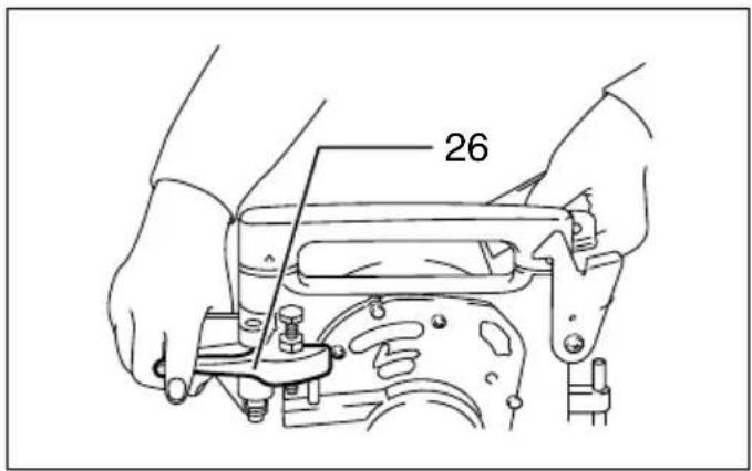
Push down the right-hand grip while raising the left-hand grip. Make sure that the adjusting hex bolt slips into place securely. (Fig. 11)
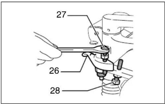
Loosen the hex nut securing the adjusting hex bolt. Turn the adjusting hex bolt until the cutter chain reaches the desired position, then tighten the hex nut. (Fig. 12)
WARNING:
- When using pressure to turn the adjusting hex bolt or hex nut, be careful not to allow the adjusting hex bolt to slip off the set position.
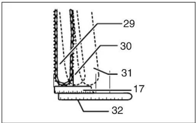
To bring the cutter chain back to the perpendicular (original) position, pull the lever (C) toward you while pressing down on the right-hand grip and slightly raising the left-hand grip and move the cutter chain back to its original position.
When cutting a hole, first use the perpendicular position, then No. 1 set position and finally No. 2 set position. Always safely hook the tool head back onto the hook when changing the cutter chain position. (Fig. 13)
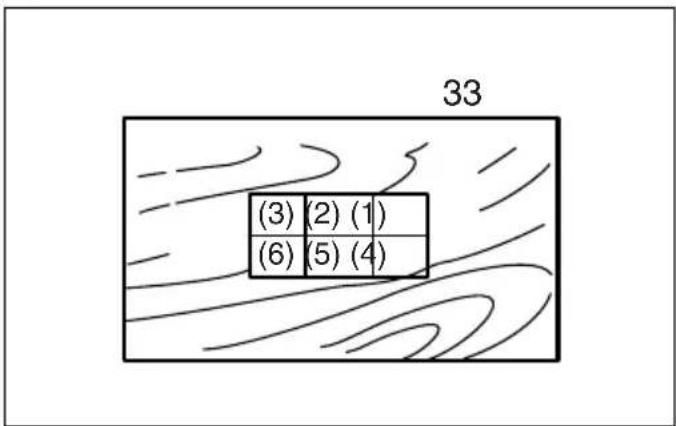
When enlarging a hole both transversely and longitudinally, cut the holes in the order indicated from No. (1) to (6) as shown. This makes for more easy and efficient hole enlargement. (Fig. 14)
WARNING:
- Never attempt to enlarge a hole with the cutter chain still within the hole. This will cause unstable and dangerous operation.
- Never angle the cutter chain when cutting the first hole, or a dangerous kickback may result. Always have the cutter chain set to the perpendicular position when cutting the first hole.
Lap joints up to 130 mm can be cut with this tool. (Fig. 15)
NOTE:
- Lap joints can be cut only on the front (side away from you) of the workpiece.
MAINTENANCE
CAUTION:
• Always be sure that the tool is switched off and unplugged before attempting to perform inspection or maintenance.
- Never use gasoline, benzine, thinner, alcohol or the like. Discoloration, deformation or cracks may result.
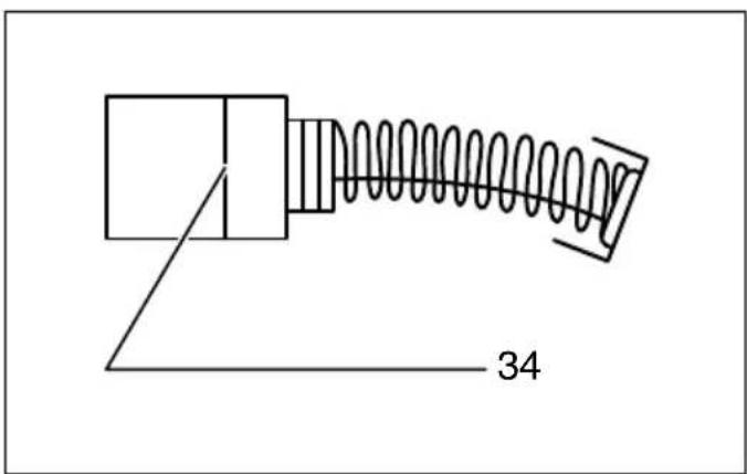
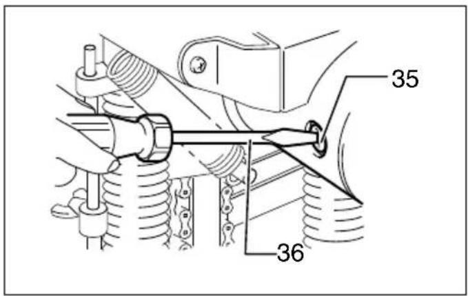
Replacing carbon brushes (Fig. 16)
Remove and check the carbon brushes regularly. Replace when they wear down to the limit mark. Keep the carbon brushes clean and free to slip in the holders. Both carbon brushes should be replaced at the same time. Use only identical carbon brushes.
Use a screwdriver to remove the brush holder caps. Take out the worn carbon brushes, insert the new ones and secure the brush holder caps. (Fig. 17)
Lubrication
After use, remove dirt, chips and foreign matter adhering to the tool. Then oil the moving parts (especially cutter chain) and the contact portions.
To maintain product SAFETY and RELIABILITY, repairs, any other maintenance or adjustment should be performed by Makita Authorized Service Centers, always using Makita replacement parts.
OPTIONAL ACCESSORIES
CAUTION:
• These accessories or attachments are recommended for use with your Makita tool specified in this manual. The use of any other accessories or attachments might present a risk of injury to persons. Only use accessory or attachment for its stated purpose.
If you need any assistance for more details regarding these accessories, ask your local Makita Service Center.
- Cutter chain
- Chain bar for 30 mm
- Sprocket 4 for 30 ~mm
- Oil supply (100 cc)
NOTE:
- Some items in the list may be included in the tool package as standard accessories. They may differ from country to country.
Noise
ENG905-1
The typical A-weighted noise level determined according to EN61029:
Sound pressure level ( L_pA ): 90 dB (A)
Sound power level ( L_WA ): 103 dB (A)
Uncertainty (K): 3 dB (A)
Wear ear protection.
Vibration
ENG900-1
The vibration total value (tri-axial vector sum) determined according to EN61029:
Vibration emission (ah): 2.5 m/s ^2 or less
Uncertainty (K): 1.5 m/s ^4
ENG901-1
- The declared vibration emission value has been measured in accordance with the standard test method and may be used for comparing one tool with another.
- The declared vibration emission value may also be used in a preliminary assessment of exposure.
WARNING:
- The vibration emission during actual use of the power tool can differ from the declared emission value depending on the ways in which the tool is used.
- Be sure to identify safety measures to protect the operator that are based on an estimation of exposure in
the actual conditions of use (taking account of all parts of the operating cycle such as the times when the tool is switched off and when it is running idle in addition to the trigger time).
For European countries only
ENH003-13
EC Declaration of Conformity
We Makita Corporation as the responsible
manufacturer declare that the following Makita
machine(s):
Designation of Machine:
Chain Mortiser
Model No./ Type: 7104L
are of series production and
Conforms to the following European Directives:
2006/42/EC
And are manufactured in accordance with the following
standards or standardised documents:
EN61029
The technical documentation is kept by our authorised
representative in Europe who is:
Makita International Europe Ltd.
Michigan Drive, Tongwell,
Milton Keynes, Bucks MK15 8JD, England
30.1.2009

Tomoyasu Kato
Director
Makita Corporation
3-11-8, Sumiyoshi-cho,
Anjo, Aichi, 446-8502, JAPAN
Michigan Drive, Tongwell,
Milton Keynes, Bucks MK15 8JD, Angleterre
30.1.2009

Tomoyasu Kato
Directeur
Makita Corporation
3-11-8, Sumiyoshi-cho,
Anjo, Aichi, 446-8502, JAPAN
Michigan Drive, Tongwell,
Milton Keynes, Bucks MK15 8JD, England
30.1.2009

Tomoyasu Kato
Direktor
Makita Corporation
3-11-8, Sumiyoshi-cho,
Anjo, Aichi, 446-8502, JAPAN
Michigan Drive, Tongwell,
Milton Keynes, Bucks MK15 8JD, Inghilterra
30.1.2009

Tomoyasu Kato
Direttore
Makita Corporation
3-11-8, Sumiyoshi-cho,
Anjo, Aichi, 446-8502, JAPAN
WAARSCHUWING Lees alle
Michigan Drive, Tongwell,
Milton Keynes, Bucks MK15 8JD, Engeland
-
- 2009

Tomoyasu Kato
Directeur
Makita Corporation
3-11-8, Sumiyoshi-cho,
Anjo, Aichi, 446-8502, JAPAN
Michigan Drive, Tongwell,
Milton Keynes, Bucks MK15 8JD, Inglaterra
-
- 2009

Tomoyasu Kato Director
Makita Corporation
3-11-8, Sumiyoshi-cho,
Anjo, Aichi, 446-8502, JAPAN
Michigan Drive, Tongwell,
Milton Keynes, Bucks MK15 8JD, Inglaterra
30.1.2009

Tomoyasu Kato
Director
Makita Corporation
3-11-8, Sumiyoshi-cho,
Anjo, Aichi, 446-8502, JAPAN
Michigan Drive, Tongwell,
Milton Keynes, Bucks MK15 8JD, England
30.1.2009

Tomoyasu Kato
Direktør
Makita Corporation
3-11-8, Sumiyoshi-cho,
Anjo, Aichi, 446-8502, JAPAN
SVENSKA (Originalanvisningar)
Allmän överblick
Michigan Drive, Tongwell,
Milton Keynes, Bucks MK15 8JD, England
30.1.2009

Tomoyasu Kato
Direktör
Makita Corporation
3-11-8, Sumiyoshi-cho,
Anjo, Aichi, 446-8502, JAPAN
Michigan Drive, Tongwell,
Milton Keynes, Bucks MK15 8JD, England
-
- 2009

Tomoyasu Kato
Direktør
Makita Corporation
3-11-8, Sumiyoshi-cho,
Anjo, Aichi, 446-8502, JAPAN
Michigan Drive, Tongwell,
Milton Keynes, Bucks MK15 8JD, England
30.1.2009

Tomoyasu Kato
Director
Makita Corporation
3-11-8, Sumiyoshi-cho,
Anjo, Aichi, 446-8502, JAPAN
Michigan Drive, Tongwell,
Milton Keynes, Bucks MK15 8JD, England
-
- 2009

Tomoyasu Kato
Διευθυντής
Makita Corporation
3-11-8, Sumiyoshi-cho,
Anjo, Aichi, 446-8502, JAPAN
Makita Corporation
Anjo, Aichi, Japan
883685A992 www.makita.com