
PJ7000 - Milling machine MAKITA - Free user manual and instructions
Find the device manual for free PJ7000 MAKITA in PDF.


| Product type | Biscuit joiner (biscuit slot cutter) |
| Brand | Makita |
| Model | PJ7000 |
| No-load speed | 11 000 min⁻¹ |
| Blade diameter | 100 mm |
| Max. groove depth | 20 mm (without rubber studs) |
| Depth adjustment | 6 positions: 8, 10, 12.3, 13, 14.7, and 20 mm |
| Angle guide | Adjustable height, removable |
| Front plate | Tilting from 0° to 90° (stops at 0°, 45°, 90°) |
| Switch | Slide switch with lock-on feature |
| Overall length | 302 mm |
| Net weight | 2.8 kg |
| Power supply | Single-phase mains, double insulation, no earth connection |
| Rated voltage | 230 V ~ 50 Hz (Europe) |
| Safety class | /16 (double insulation) |
| Sound pressure level | 89 dB(A) (grooving MDF) |
| Sound power level | 97 dB(A) (grooving MDF) |
| Vibration (grooving MDF) | 1.6 m/s² (uncertainty K=1.5 m/s²) |
| Dust extraction system | Connector for vacuum cleaner (diameter 26 mm) and dust bag included |
| Included accessories | Angle guide, dust bag, spacer plate, lock nut wrench |
| Maintenance | Clean ventilation slots regularly; no solvents |
| Repairability | Repairs exclusively by an authorized Makita service center |
| Blade standards | Use only blades conforming to standard EN847-1 |
Frequently Asked Questions - PJ7000 MAKITA
User questions about PJ7000 MAKITA
0 question about this device. Answer the ones you know or ask your own.
Ask a new question about this device
Download the instructions for your Milling machine in PDF format for free! Find your manual PJ7000 - MAKITA and take your electronic device back in hand. On this page are published all the documents necessary for the use of your device. PJ7000 by MAKITA.
USER MANUAL PJ7000 MAKITA
GB Plate Joiner Instruction Manual
natural_image
Technical line drawing of a mechanical power tool (no text or symbols present)

1
2

3

4
5

6

7

natural_image
Technical line drawing of a mechanical assembly with labeled component '31' (no text or symbols beyond label)012259
0122718
9
012267
10
012252

11 12
natural_image
Line drawing of a wooden plank being cut with a clamped tool, no text or symbols present004589012272

natural_image
Line drawing of a mechanical clamp or clamping device with a handle and base, no text or symbols present13 14
natural_image
Technical line drawing showing a corner structure with hatching patterns and a small wooden plank (no text or symbols)004584012274

natural_image
Line drawing of a sewing machine needle cutting into a flat surface, with no text or symbols present.15 16

natural_image
Technical line drawing of a mechanical device with an arrow indicating motion (no text or symbols present)012261
012263

natural_image
Technical line drawing showing a structural joint with hatching patterns and a separate wooden plank (no text or symbols)17 18

natural_image
Technical line drawing of a mechanical device with an arrow indicating motion (no text or symbols present)004585
012263
natural_image
Technical line drawing of a sewing machine with a downward arrow indicating compression (no text or symbols)19 20
natural_image
Technical line drawing of two wooden joint components: a L-shaped bracket and a corner joint (no text or symbols)004586012262
natural_image
Technical line drawing of a mechanical device with a lever and base plate (no text or symbols)21 22

natural_image
Technical line drawing of a wooden joint with two views: one showing grain patterns and the other showing a cut edge (no text or symbols)004587012264
natural_image
Technical line drawing of a mechanical device with a lever and handle (no text or symbols)23 24

natural_image
Diagram showing wood grain structure with a close-up of a vertical pipe or pipe fitting (no text or symbols)012265
004588
natural_image
Technical line drawing of a mechanical device with an arrow indicating motion (no text or symbols present)25 26

012263 012272
Explanation of general view
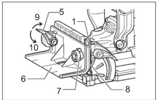
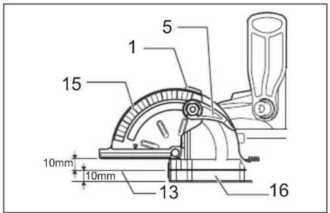
| 1 Pointer | 12 Up | 23 Shaft lock |
| 2 Stopper | 13 Center of blade thickness | 24 Dust bag |
| 3 Adjusting screw | 14 Fence | 25 Fastener |
| 4 Rubber spike | 15 Angle scale | 26 Dust nozzle |
| 5 Lock lever | 16 Blade cover | 27 Handle |
| 6 Angle guide | 17 Set plate | 28 Front grip |
| 7 Knob | 18 Thickness of set plate | 29 Exhaust vent |
| 8 Scale | 19 Lock nut | 30 Inhalation vent |
| 9 Tighten | 20 Plate joiner blade | 31 Slide switch |
| 10 Loosen | 21 Inner flange | |
| 11 Down | 22 Clamp screw |
SPECIFICATIONS
GEB020-5
Model PJ7000
Type of blade ..... Plate joiner
Max. grooving depth
Plate joiner blade.... 20 mm
No load speed (n0) 11,000 min -1
Blade diameter 100 mm
Overall length 302 mm
Net weight 2.8 kg
Safety class /
- Due to our continuing program of research and development, the specifications herein are subject to change without notice.
- Specifications may differ from country to country.
- The net weight value includes the attachment(s) for normal and safe use which are specified in the instruction manual.
ENE013-1
Intended use
The tool is intended for cutting crescent shaped slots for the placement of flat wooden dowels or biscuit by a plunging action.
ENF002-2
Power supply
The tool should be connected only to a power supply of the same voltage as indicated on the nameplate, and can only be operated on single-phase AC supply. They are double-insulated and can, therefore, also be used from sockets without earth wire.
GEA010-3
General power tool safety warnings
⚠ WARNING Read all safety warnings, instructions, illustrations and specifications provided with this power tool. Failure to follow all instructions listed below may result in electric shock, fire and/or serious injury.
Save all warnings and instructions for future reference.
The term “power tool” in the warnings refers to your mains-operated (corded) power tool or battery-operated (cordless) power tool.
Plate joiner safety warnings
- Blades must be rated for at least the speed marked on the tool. Blades running over rated speed can fly apart and cause injury.
- Always use the guard. The guard protects the operator from broken blade fragments and unintentional contact with the blade.
- Hold power tool by insulated gripping surfaces, because the blade may contact its own cord. Cutting a "live" wire may make exposed metal parts of the power tool "live" and could give the operator an electric shock.
- Use only the blades specified for this tool.
- Never operate the tool with the blade locked in exposed position or without the blade cover secured properly in place.
- Make sure that the blade slides smoothly before operation.
- Check the blades carefully for cracks or damage before operation. Replace cracked or damaged blades immediately.
- Make sure that the flange fits in the arbor hole when installing the blade.
- Inspect for and remove all nails or foreign matter from the workpieces before operation.
- Always place the workpieces on a stable workbench.
- Secure the workpieces firmly with clamp or vise.
- NEVER wear gloves during operation.
- Hold the tool firmly with both hands.
- Keep your hands and body away from the grooving area.
- Run the tool for a while without the blade pointing toward anybody. Watch for vibration or wobbling that could indicate poor installation or a poorly balanced blade.
- Never reach your hands underneath the workpieces while the blade is rotating.
- Do not leave the tool running unattended.
- Always be sure that the tool is switched off and unplugged before making any adjustments or replacing the blade.
- Some material contains chemicals which may be toxic. Take caution to prevent dust inhalation and skin contact. Follow material supplier safety data.
Additional safety warnings:
-
(For European countries only) Always use the blade which conforms to EN847-1, if intended for wood and analogous materials.
-
Do not use blunt or damaged blades.
- Do not use the tool with damaged guards.
- Wear a dust mask and hearing protection when you use the tool.
SAVE THESE INSTRUCTIONS.
FUNCTIONAL DESCRIPTION
CAUTION:
• Always be sure that the tool is switched off and unplugged before adjusting or checking function on the tool.
Adjusting the depth of groove (Fig. 1)
6 grooving depths can be preset according to the size of biscuit to be used.
Refer to the table below for the correspondence between the sizes marked on the stopper and the biscuit size. Fine adjustments to the grooving depth can be made by turning the adjusting screw after loosening the hex nut. This may become necessary after the blade has been resharpened a few times.
| Size on stopper 0 10 20 S | D | MAX | ||||
| Biscuit size | 0 | 10 | 20 | — | — | — |
| Depth of groove | 8 mm | 10 mm | 12.3 mm | 13 mm | 14.7 mm | 20 mm* |
* With the rubber spikes removed.
012681
Angle guide (Fig. 2 & 3)
The angle guide height can be moved up and down to adjust the position of the blade in relation to the top of the workpiece.
To adjust the angle guide height, loosen the lock lever down and rotate the knob until the pointer points to the desired scale graduation marked on the angle guide.
Then tighten the lock lever up to secure the angle guide. The scale on the angle guide indicates the distance from the top of the workpiece to the center of the blade thickness.
The angle guide is removable from the fence according to the need of your work. To remove the angle guide, loosen the lock lever and turn the knob clockwise until it comes out of the upper end of the fence.
Fence (Fig. 4 & 5)
NOTE:
- Remove the angle guide according to the need of your work when using the tool with the angle of the fence adjusted to other than 0irc . When you need to use the angle guide under the above condition, be sure to adjust the depth of groove to get a proper depth.
The angle of the fence can be adjusted between 0irc and 90irc (positive stops at 0irc , 45irc and 90irc ). To adjust the angle, loosen the lock lever and tilt the fence until the pointer points to the desired graduation on the angle scale. Then tighten the lock lever to secure the fence. When the fence is set at 90irc , both the distance from the center of the blade thickness to the fence and the distance from the center of the blade thickness to the bottom of the blade cover are 10 mm.
Set plate (Fig. 6 & 7)
Use the set plate as shown in Fig. 6 & 7 when cutting slots in thin workpieces.
WARNING:
DO NOT let comfort or familiarity with product (gained from repeated use) replace strict adherence to safety rules for the subject product. MISUSE or failure to follow the safety rules stated in this instruction manual may cause serious personal injury.
Switch action (Fig. 8)
CAUTION:
- Before plugging in the tool, always check to see that the slide switch actuates properly and returns to the "OFF" position when the rear of the slide switch is depressed.
- Switch can be locked in "ON" position for ease of operator comfort during extended use. Apply caution when locking tool in "ON" position and maintain firm grasp on tool.
To start the tool, slide the slide switch toward the "I (ON)" position. For continuous operation, press the front of the slide switch to lock it.
To stop the tool, press the rear of the slide switch, then slide it toward the "O (OFF)" position.
ASSEMBLY
CAUTION:
- Always be sure that the tool is switched off and unplugged before carrying out any work on the tool.
Removing or installing the blade (Fig. 9)
CAUTION:
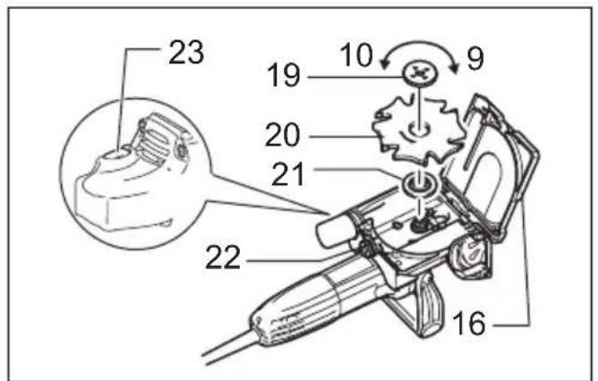
- When installing the plate joiner blade, mount the inner flange with the side marked "22" facing toward you.
To remove the blade, loosen the clamp screw and open the blade cover. Push the shaft lock and loosen the lock nut using the lock nut wrench. To install the blade, first mount the inner flange.
Then mount the blade and the lock nut. Securely tighten the lock nut using the lock nut wrench. Close the blade cover and tighten the clamp screw to secure the blade cover.
CAUTION:
- Use only Makita lock nut wrench provided to remove or install the blade.
- Always check the depth of groove after replacing the blade. Readjust it if necessary.
Dust
WARNING:
Depending on the material being worked on and the accessory used, the dust created by use of the tool can be harmful. The user is recommended to use an appropriate dust extractor to reduce exposure.
See the "OPTIONAL ACCESSORIES" section in this instruction manual for all optional dust extractor attachments available.
Additional Warnings:
- To prevent dust inhalation, it is recommended to also wear an FFP2 dust mask or P2 respirator.
- Read the "MAINTENANCE" section of the instruction manual of the connected dust extractor to keep the dust collection effective.
- Follow all applicable regulatory requirements for dust control in the country where the work is being conducted.
- Do not use a dust extractor for metalworking with power tools. Metal particles produced during metalworking can ignite accumulated dust and damage the dust filter inside dust extractors, posing a serious fire hazard.
- For European countries only The user is recommended to use an M or H dust class extractor (as defined in EN 60335-2-69).
For help and support regarding dust extractors, please contact your local Makita Service Center.
Connecting with a dust extractor
Connect a hose of the Makita vacuum cleaner to the dust nozzle of the tool using the front cuff 22.
The inner diameter of the dust nozzle for the hose connection is 26 mm.
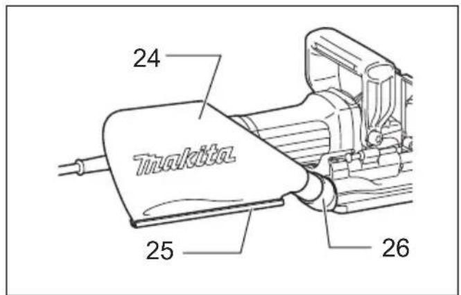
Installing or removing dust bag (Fig. 10)
To attach the dust bag, fit it onto the dust nozzle. If the dust bag becomes an obstacle to your work, turn the dust nozzle to change the dust bag position.
When the dust bag is about half full, switch off and unplug the tool. Remove the dust bag from the tool and pull the bag's fastener out. Empty the dust bag by tapping it lightly to remove as much of the dust as possible.
NOTE:
- If you connect a Makita vacuum cleaner to your plate joiner, more efficient and cleaner operations can be performed.
OPERATION (Fig. 11)
Hold the tool firmly.
How to make joints
WARNING:
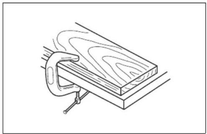
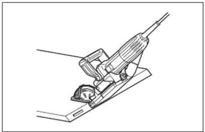
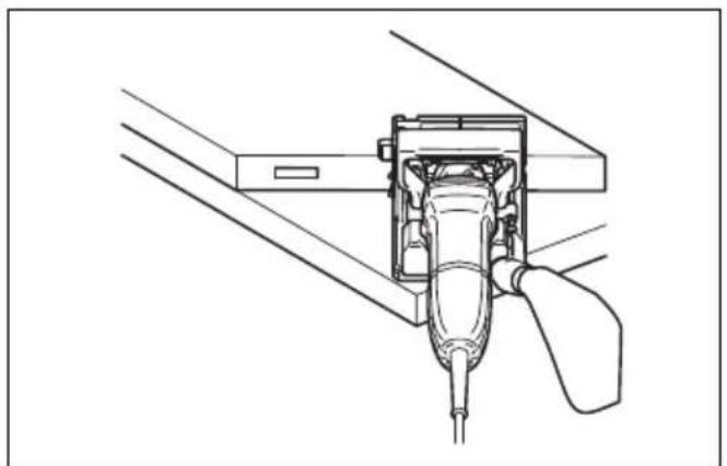
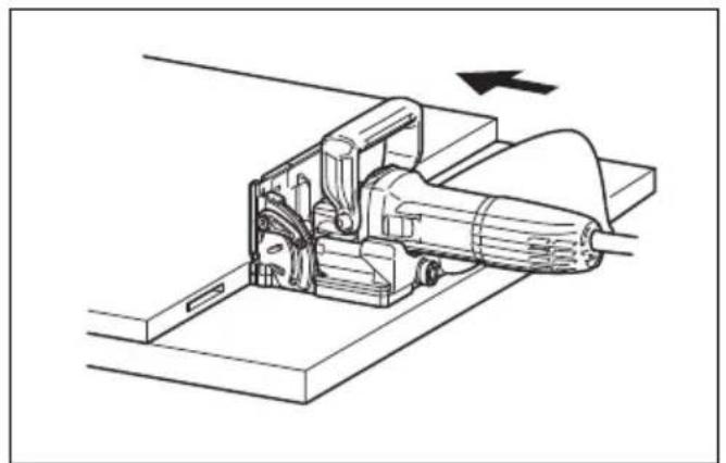
• Always clamp the workpiece to the workbench before each operation. (Fig. 12 & 13)
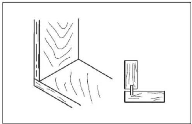
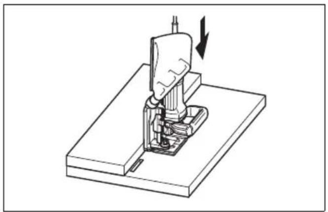
Corner Joint (Fig. 14, 15 & 16)
T-Butt Joint (Fig. 17, 18 & 19)
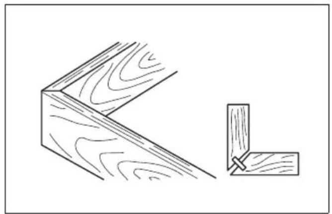
Miter Joint (Fig. 20 & 21)
Frame Joint (Fig. 22 & 23)
Edge-To-Edge Joint (Fig. 24 & 25)
To make joints, proceed as follows:
- Fit the two workpieces together as they will appear in the finished joint position.
- Mark the center of the intended biscuit grooves on the workpiece using a pencil.
NOTE:
- The center of grooves should be at least 50 mm from the outer edge of the workpieces.
- Allow 100 mm – 150 mm between grooves in multiple biscuit application.
3. For Corner Joint and T-Butt Joint only
Clamp the vertical workpiece to the workbench. For Miter Joint only
Clamp one workpiece to the workbench with the mitered edge facing up.
For Frame Joint and Edge-To-Edge Joint only Clamp one workpiece to the workbench.
-
Set the depth of groove according to the size of biscuit to be used. Refer to the table in the "Adjusting the depth of groove" section.
-
Adjust the angle guide height so that the blade is centered in the board thickness.
-
Align the center mark on the base with the pencil line on the workpiece.
-
Switch on the tool and gently push it forward to extend the blade into the workpiece.
-
Gently return the tool to the original position after the adjusting screw reaches the stopper.
9. For Corner Joint and T-Butt Joint only
Clamp the horizontal workpiece to the workbench.
For Miter Joint only
Clamp the other workpiece to the workbench with the mitered edge facing up.
For Frame Joint and Edge-To-Edge Joint only
Clamp the other workpiece to the workbench.
10. For Corner Joint only
Place the tool on the workpiece so that the blade is facing down.
For T-Butt Joint only
Remove the angle guide from the tool. Place the tool on the workpiece so that the blade is facing down.
- Repeat the steps 6 - 8 to groove in the horizontal or the other workpiece.
If you do not need to center the blade in the board thickness, proceed as follows:
For Corner Joint, Miter Joint, Frame Joint and Edge-To-Edge Joint only
- Remove the angle guide from the tool. Set the fence at 90irc for Corner Joint, Frame Joint and Edge-To-Edge Joint or at 45irc for Miter Joint.
- Follow steps 1 – 11 excluding steps 5 and 10 described above.
For T-Butt Joint only
- Fit the two workpieces together as they will appear in the finished joint position.
- Lay the vertical workpiece on the horizontal one. Clamp both workpieces to the workbench.
- Remove the angle guide from the tool.
- Follow the steps 2, 4, 6, 7, 8 and 11 described above.
MAINTENANCE
CAUTION:
- Always be sure that the tool is switched off and unplugged before attempting to perform inspection or maintenance.
- Never use gasoline, benzine, thinner, alcohol or the like. Discoloration, deformation or cracks may result.
The tool and its air vents have to be kept clean. Regularly clean the tool's air vents or whenever the vents start to become obstructed. (Fig. 26)
To maintain product SAFETY and RELIABILITY, repairs, carbon brush inspection and replacement, any other maintenance or adjustment should be performed by Makita Authorized Service Centers, always using Makita replacement parts.
OPTIONAL ACCESSORIES
CAUTION:
• These accessories or attachments are recommended for use with your Makita tool specified in this manual. The use of any other accessories or attachments might present a risk of injury to persons. Only use accessory or attachment for its stated purpose.
If you need any assistance for more details regarding these accessories, ask your local Makita Service Center.
- Angle guide
- Dust bag
- Set plate 4
- Lock nut wrench 20
- Plate joiner blades
NOTE:
- Some items in the list may be included in the tool package as standard accessories. They may differ from country to country.
ENG905-1
Noise
The typical A-weighted noise level determined according to EN62841:
Work mode: cutting grooves in MDF Sound pressure level ( LpA ): 89 dB (A) Sound power level ( LWA ): 97 dB (A) Uncertainty (K): 3 dB (A)
The typical A-weighted noise level determined according to EN60745:
Work mode: operation without load Sound pressure level ( LpA ): 86 dB (A) Sound power level ( LWA ): 97 dB (A) Uncertainty (K): 3 dB (A)
NOTE:
- The declared noise emission value(s) has been measured in accordance with a standard test method and may be used for comparing one tool with another.
- The declared noise emission value(s) can also be used in a preliminary assessment of exposure.
WARNING:
- Wear ear protection.
- The noise emission during actual use of the power tool can differ from the declared total value(s) depending on the ways in which the tool is used.
- Be sure to identify safety measures to protect the operator that are based on an estimation of exposure in the actual conditions of use (taking account of all parts of the operating cycle such as the times when the tool is switched off and when it is running idle in addition to the trigger time).
Vibration
The continuous vibration total value (tri-axial vector sum) determined according to EN62841/ EN60745:
Work mode: cutting grooves in MDF Vibration emission ( ah ): 1.6 m/s 2 Uncertainty (K): 1.5 m/s 2
NOTE:
- The declared vibration total value(s) has been measured in accordance with a standard test method and may be used for comparing one tool with another.
- The declared vibration total value(s) can also be used in a preliminary assessment of exposure.
WARNING:
- The vibration emission during actual use of the power tool can differ from the declared total value(s) depending on the ways in which the tool is used. - Be sure to identify safety measures to protect the operator that are based on an estimation of exposure in the actual conditions of use (taking account of all parts of the operating cycle such as the times when the tool is switched off and when it is running idle in addition to the trigger time).
The following shows the mean values of the peak amplitude of the acceleration from repeated shock vibrations, pF , with corresponding uncertainty (K) determined according to EN62841.
Work mode: cutting grooves in MDF pF : 165 m/s 2 Uncertainty (K): 88 m/s 2
NOTE:
• These declared values should not be used to determine hand arm vibration exposure.
Declarations of Conformity
For European countries only
The EU Declaration of Conformity can be accessed from the following URL.

https://support.makita.biz/doc/doc_index.html
For the UK
The Declaration of conformity is included in Annex A to this instruction manual.
Descriptif
Type freesblad ....Lamellen freesmachine
Maximale freesdiepte
Lamellenfreesblad 20 mm
Nullasttoerental (n0).... 11 000 min
Zaagbladdiameter 100 mm
VEILIGHEIDSWAARSCHUWINGEN VOOR LAMELLEN FREESMACHINE
OPTIONELE ACCESSOIRES
LET OP:
- SPECIFICATIONS
- Model PJ7000
- Intended use
- Power supply
- General power tool safety warnings
- Plate joiner safety warnings
- Additional safety warnings:
- SAVE THESE INSTRUCTIONS.
- FUNCTIONAL DESCRIPTION
- CAUTION:
- Adjusting the depth of groove (Fig. 1)
- Angle guide (Fig. 2 & 3)
- Fence (Fig. 4 & 5)
- NOTE:
- Set plate (Fig. 6 & 7)
- WARNING:
- Switch action (Fig. 8)
- ASSEMBLY
- Removing or installing the blade (Fig. 9)
- Dust
- Additional Warnings:
- Connecting with a dust extractor
- Installing or removing dust bag (Fig. 10)
- OPERATION (Fig. 11)
- How to make joints
- For Corner Joint and T-Butt Joint only
- For Corner Joint and T-Butt Joint only
- For Miter Joint only
- For Corner Joint only
- For T-Butt Joint only
- For Corner Joint, Miter Joint, Frame Joint and Edge-To-Edge Joint only
- MAINTENANCE
- OPTIONAL ACCESSORIES
- Noise
- Vibration
- Declarations of Conformity
- For European countries only
- For the UK
- VEILIGHEIDSWAARSCHUWINGEN VOOR LAMELLEN FREESMACHINE
- OPTIONELE ACCESSOIRES
- LET OP:
Brand : MAKITA
Model : PJ7000
Category : Milling machine