
1993397 - Multifunction tool MAKITA - Free user manual and instructions
Find the device manual for free 1993397 MAKITA in PDF.
| Product Type | Multi-function power tool attachment (brush broom/squeegee broom) |
| Brand | Makita |
| Model Reference | 1993397 (models BR400MP and SW400MP) |
| Brush Broom Model | BR400MP |
| Squeegee Broom Model | SW400MP |
| Dimensions (BR400MP) | 1,145 × 600 × 362 mm (length × width × height) |
| Dimensions (SW400MP) | 1,159 × 600 × 362 mm |
| Net Weight (BR400MP) | 6.3 kg |
| Net Weight (SW400MP) | 7.2 kg |
| Brush Width | 600 mm |
| Brush Outer Diameter | 250 mm |
| Squeegee Roller Width | 590 mm |
| Squeegee Roller Outer Diameter | 265 mm |
| Approved Power Units | DUX60, DUX18, UX01G (cordless), EX2650LH (petrol) |
| Power Source | Depends on power unit (battery or petrol) |
| Main Uses | Sweeping floors and paths (BR400MP); removing wet materials and water (SW400MP) |
| Usage | Commercial |
| Required Protective Equipment | Safety helmet, safety glasses, anti-noise headband, sturdy non-slip shoes, gloves, long trousers, long sleeves |
| Routine Maintenance | Clean with water, lubricate gear case and drive axle every 25 hours, visual inspection before each use |
| Spare Parts | Use only genuine Makita parts |
| After-Sales Service | Makita authorized service center |
| Compliance Standards | 2006/42/EC, EN 60335-1, EN 60335-2-72 |
| Lubrication Interval | Every 25 operating hours |
Frequently Asked Questions - 1993397 MAKITA
User questions about 1993397 MAKITA
0 question about this device. Answer the ones you know or ask your own.
Ask a new question about this device
Download the instructions for your Multifunction tool in PDF format for free! Find your manual 1993397 - MAKITA and take your electronic device back in hand. On this page are published all the documents necessary for the use of your device. 1993397 by MAKITA.
USER MANUAL 1993397 MAKITA
SPECIFICATIONS
| Model: BR400MP | |
| Dimensions: length x width x height (with brushes) 1,145 mm x 600 | mm x 362 mm |
| Net weight 6.3 kg | |
| Brush width 600 mm | |
| Outer diameter of the brush 250 mm |
| Model: SW400MP | |
| Dimensions: length x width x height (with sweep drums) 1,159 mm x 600 mm x 362 mm | |
| Net weight 7.2 kg | |
| Sweep drum width 590 mm | |
| Outer diameter of the sweep drum 265 mm | |
- Due to our continuing program of research and development, the specifications herein are subject to change without notice.
• Specifications may differ from country to country.
Approved power unit
This attachment is approved to use only with the following power unit(s):
- DUX60, DUX18, UX01G Cordless Multi Function Power Head
• EX2650LH Multi Function Power Head
⚠ WARNING: Never use the attachment with non-approved power unit. Non-approved combination may cause serious injury.
Symbols
The following symbols are used on the attachment and this instruction manual. Understand these definitions.
 | Take Particular care and attention! |
 | Read instruction manual. |
 | Wear protective helmet, eye and ear protection! |
 | Wear sturdy boots with nonslip soles. Steeltoed safety boots are recommended! |
 | Keep bystanders at least 5 m (17 ft) away. |
 | The brushes or sweep drums rotate in the direction of the arrow. |
 | When attaching the brushes or sweep drums, make sure that the gear case is facing upward. |
Intended use
BR400MP
This attachment is designed for only the purpose of sweeping ground and paths in conjunction with an approved power unit. Never use the attachment for other purposes. Abusing the attachment may cause serious injury. This attachment is intended for commercial use.
SW400MP
This attachment is designed for only the purpose of clearing wet materials, such as leaves, dirt, and removing water from solid surfaces in conjunction with an approved power unit. Never use the attachment for other purposes. Abusing the attachment may cause serious injury. This attachment is intended for commercial use.
Declarations of Conformity
For European countries only
We as the manufacturers: Makita Europe N.V., Business address: Jan-Baptist Vinkstraat 2 3070 Kortenberg BELGIUM. Authorize Kazuhisa Makino for the compilation of the technical file and declare under our sole responsibility that the product(s); Designation: Power Brush Attachment / Power Sweep Attachment. Designation of Type(s): BR400MP / SW400MP. Fulfills all the relevant provisions of 2006/42/EC and are manufactured in accordance with the following Harmonised Standards: EN 60335-1:2012+A11:2014+A13:2017+A1:2019+A14:2019+A2:2019+A15:2021, EN 60335-2-72:2012. Place and date of declaration: Kortenberg, Belgium. 1. 8. 2023 Responsible person: Kazuhisa Makino, Director - Makita Europe N.V.

Declaration of Conformity (For UK)
For UK only
We as the manufacturers: Makita Europe N.V., Business address: Jan-Baptist Vinkstraat 2 3070 Kortenberg BELGIUM. Authorize Kazuhisa Makino for the compilation of the technical file and declare under our sole responsibility that the product(s); Designation: Power Brush Attachment / Power Sweep Attachment. Designation of Type(s): BR400MP / SW400MP.
Fulfills all the relevant provisions of S.I. 2008/1597 (as amended) and are manufactured in accordance with the following Designated Standards: EN 60335-1:2012+A11:2014+A13:2017+A1:2019+A14:2019+A2:2019+A15:2021, EN 60335-2-72:2012.
Place and date of declaration: Kortenberg, Belgium. 1. 8. 2023
Responsible person: Kazuhisa Makino, Director - Makita Europe N.V.
Importer: Makita (UK) Limited, Michigan Drive, Tongwell, Milton Keynes, Buckinghamshire, MK15 8JD, UK

SAFETY WARNINGS
Power brush / power sweep safety warnings
WARNING: Read all safety warnings, instructions, illustrations and specifications provided with this machine as well as the instruction manual of the power unit before using. Failure to follow all instructions listed below may result in fire and/or serious injury to the operator and/or bystanders.
Save all warnings and instructions for future reference.
The term “power brush / power sweep” and “machine” in the warnings and precautions refer to the combination of the attachment and the power unit. The term “motor” in the warnings and precautions refers to the engine or electric motor of the power unit.
General safety
- First-time or inexperienced operator should ask the dealer for training in all operation of the machine. Never allow children, persons with reduced physical, sensory or mental capabilities or lack of experience and knowledge or people unfamiliar with the instructions to use the machine. Children should be supervised to ensure that they do not play with the machine.
-
It is recommended only to lend the machine to people who have proven to be experienced. Always hand over the instruction manual.
-
Stay alert, watch what you are doing and use common sense when operating the machine. Do not use the machine while you are tired, ill, or under the influence of drugs, alcohol or medication. A moment of inattention while operating the machine may result in serious personal injury.
-
Avoid using the machine in bad weather conditions especially when there is a risk of lightning.
-
Follow your national and local regulation for use of outdoor power machines.
-
Never attempt to modify the machine.
-
Keep in mind that the operator or user is responsible for accidents or hazards occurring to other people or their property.
Work area safety
WARNING: Keep the power brush / power sweep away from electric lines and communication cables. Touching or approaching high-voltage lines with power brush / power sweep can result in death or serious injury. Watch power lines and electrical fences around the work area before starting operation.
- Operate the machine under good visibility and daylight conditions only. Do not operate the machine in darkness or fog.
- Start and operate the engine only outdoors in a well ventilated area. Operation in a confined or poorly ventilated area can result in death due to suffocation or carbon monoxide poisoning.
- Before operation, examine the work area for wire fences, stones, or other solid objects. They can damage the brushes or sweep drums.
- During operation, never stand on an unstable or slippery surface or a steep slope. During the cold season, beware of ice and snow and always ensure secure footing.
- Avoid working close to fences, stumps or root of trees. They can damage the brushes or sweep drums.
- Avoid working close to buildings, cars and other properties. Stones and debris hit by the power brush / power sweep may damage them.
- Cleaning the synthetic floor may generate static electricity, and there is a risk of electric shock or accidents.
Personal protective equipment
-
Always wear heavy, long pants, sturdy boots, gloves, and a long-sleeve shirt. Do not wear loose clothing, jewelry, short pants, sandals, or go barefoot. Secure hair so it is above shoulder level.
-
Always wear protective goggles to protect your eyes from injury when using the machine. The goggles must comply with ANSI Z87.1 in the USA, EN 166 in Europe, or AS/NZS 1336 in Australia/New Zealand. In Australia/New Zealand, it is legally required to wear a face shield to protect your face, too.

It is an employer's responsibility to enforce the use of appropriate safety protective equipments by the tool operators and by other persons in the immediate working area.
- Wear ear protection, such as ear muffs. Exposure to noise can cause hearing loss.
- Always wear sturdy shoes with a non-slip sole. This protects your feet against injuries and ensures a good footing.
- Wear a dust mask as necessary.
Refueling
- Stop the engine before refueling. Keep away from open flames and sparks. Never smoke during refueling. Otherwise fire and/or explosion may result.
- Refuel outdoors. Refueling in a closed room can cause explosion of fuel vapor.
- Avoid contact with fuel or engine oil. Do not inhale fuel vapor. If fuel or oil spills, wipe it off of the machine and/or ground immediately. If fuel spills on your clothes, change it immediately to prevent it from catching fire.
- After refueling, carefully tighten the fuel tank cap and check for fuel leak. Move at least 3 m (10 feet) away from the fueling source and site before starting engine.
- Only transport and store fuel in approved containers. Keep children away from the stored fuel.
Starting up the power brush / power sweep
- Before assembling or adjusting the machine, switch off the motor and remove the spark plug cap or the battery cartridge.
- Before handling the brushes or sweep drums, wear protective gloves.
- Wear the personal protective equipments before starting the motor.
- Before starting the motor, inspect the machine for damages, loose screws/nuts or improper assembly. Check all control levers and switches for easy action. Clean and dry the handles.
-
Never attempt to start the motor if the machine is damaged or not fully assembled with proper guards, plates, or other safety protective devices. Otherwise serious injury may result.
-
Before starting the motor, carefully check that the brushes or sweep drums are not touching your body and other objects. Starting the motor with the brushes or sweep drums contacting with foreign object can cause serious accident.
- Before starting the motor, make sure that there is no person or animal in the work area.
- Adjust the shoulder harness and hand grip to suit the operator's body size.
- Replace the brushes or sweep drums if they are cracked, bent, or damaged. Damaged brushes or sweep drums may shatter during operation and cause serious injury.
- Start and operate the machine only outdoors in a well ventilated area. Operation in a confined or poorly ventilated area can result in death due to suffocation or carbon monoxide poisoning.
- When starting the engine, place the machine on firm ground and then maintain good balance and secure footing.
- When pulling the starter knob of the engine, hold the power unit firmly against the ground by your left hand. Never step on the drive shaft of the power unit.
- If the brushes or sweep drums rotate at idle, stop the engine and adjust the idle speed down. Otherwise unintentional contact with moving brushes or sweep drums may result in serious injury.
- Stop the motor immediately if you notice any trouble.
- Follow the instruction manual of the power unit for starting the motor.
Transportation
- Stop the motor during transportation. Otherwise unintentional start-up may cause injury.
- Ensure safe position of the machine during car transportation to avoid fuel leakage.
- Lift the entire machine from the ground when carrying the machine. Dragging the machine causes fuel tank damage and fuel leakage, resulting in fire.
- When transporting the equipment, carry it in a horizontal position by holding the shaft. Keep the hot muffler away from your body.
Operation
- During operation, keep bystanders or animals at least 5 m (17 ft) away from the power brush / power sweep. Stop the motor as soon as someone approaches.
- In the event of an emergency, switch off the motor immediately.
- If you feel any unusual condition (e.g. noise, vibration) during operation, switch off the motor. Do not use the machine until the cause is recognized and solved.
- With the engine running only at idle, attach the shoulder harness.
- During operation, use the shoulder harness. Keep the machine on your right side firmly.
-
Hold the front handle with the left hand and the rear grip with the right hand, no matter you are right-hander or left-hander. Wrap your fingers and thumbs around the handles.
-
Never attempt to operate the machine with one hand. Loss of control may result in serious or fatal injury. To reduce the risk of injuries, keep your hands and feet away from the brushes or sweep drums.
-
When operating, do not raise the brushes or sweep drums above waist height.
-
The brushes or sweep drums continue to move for a short period after releasing the throttle trigger or switching off the motor. Don't rush to contact the brushes or sweep drums.
-
Do not overreach. Keep proper footing and balance at all times. Watch for hidden obstacles such as tree stumps, roots and ditches to avoid stumbling.
-
Use extreme caution when reversing the brush or sweep drum rotation or pulling the machine toward you. If the power unit has reverse rotation function, do not use it more than necessary. When operated in reverse rotation, the power brush / power sweep will pull you if the brushes or sweep drums are on the ground.
-
Do not overload the machine capacity by attempting to push too hard at too fast a rate. The machine will do better work when used with proper load and there is less likelihood of a risk of injury.
-
Do not accelerate the motor with the brushes or sweep drums blocked. It increases the load and will damage the machine.
-
If the machine gets heavy impact or fall, check the condition before continuing work. Check the fuel system for fuel leakage and the controls and safety devices for malfunction. If there is any damage or doubt, ask our authorized service center for the inspection and repair.
-
Do not touch the gear case. The gear case becomes hot during operation.
-
Take a rest to prevent loss of control caused by fatigue. We recommend to take a 10 to 20-minute rest every hour.
-
When you leave the machine, even if it is a short time, always switch off the engine or remove the battery cartridge. The machine unattended with the engine running may be used by unauthorized person and cause serious accident.
-
Follow the instruction manual of the power unit for proper use of the control lever and switch.
- During or after operation, do not put the hot machine onto dry grass or combustible materials.
- If the brushes or sweep drums catch foreign objects, switch off the motor and remove the spark plug cap or battery cartridge, and then remove the obstructions.
- Keep your hands and feet clear of the brushes or sweep drums. Contacting the brushes or sweep drums can result in serious injury. When handling the brushes or sweep drums, stop the motor and remove the spark plug cap or battery cartridge.
- Check the brushes or sweep drums frequently during operation for cracks or damages.
- Always switch off the engine or remove the battery cartridge when removing debris or foreign objects from the brushes or sweep drums.
- Refer to the instruction manual of the power unit for how to start and control the machine.
Vibration
Exposing to excessive vibration injures blood vessels or nervous system of the operator and causes the following symptoms in the fingers, hands or wrists:
"Falling asleep" (numbness), tingling, pain, stabbing sensation, alteration of skin color or of the skin. If any of these symptoms occur, see a physician.
To reduce the risk of "white finger disease", keep your hands warm during operation and well maintain the machine and accessories.
Maintenance
- Before doing any maintenance or repair work or cleaning the machine, always switch off the motor and remove the spark plug cap or the battery cartridge. Wait until the motor gets cold.
- To reduce the risk of fire, never service the equipment in the vicinity of fire.
- Always wear protective gloves when handling the brushes or sweep drums.
- Always clean dust and dirt off the equipment. Never use gasoline, benzine, thinner, alcohol or the like for the purpose. Discoloration, deformation or cracks of the plastic components may result.
- After each use, tighten all screws and nuts, except for the carburetor adjustment screws.
- Replace the brushes or sweep drums if they are damaged.
- Do not attempt any maintenance or repair not described in this booklet or the instruction manual of the power unit. Ask our authorized service center for such work.
- Follow instructions for lubricating and changing accessories.
- Always use the genuine spare parts and accessories only. Using parts or accessories supplied by a third party may result in the equipment breakdown, property damage and/or serious injury.
- Request our authorized service center to inspect and maintain the machine at regular interval.
Storage
- Before storing the machine, perform full cleaning and maintenance. Remove the spark plug cap or the battery cartridge. Drain the fuel after the engine gets cold.
- Store the equipment in a dry and high or locked location out of reach of children.
- Do not prop the equipment against something, such as a wall. Otherwise it may fall suddenly and cause an injury.
First Aid
- In case of accident make sure that a first-aid box is available in the vicinity of the operations. Immediately replace any item taken from the first aid box.
- When asking for help, give the following information:
— Place of accident
— What happened
— Number of injured persons
— Kind of injuries
— Your name
SAVE THESE INSTRUCTIONS.
WARNING: Use of this product can create dust containing chemicals which may cause respiratory or other illnesses. Some examples of these chemicals are compounds found in pesticides, insecticides, fertilizers and herbicides. Your risk from these exposures varies, depending on how often you do this type of work. To reduce your exposure to these chemicals: work in a well ventilated area, and work with approved safety equipment, such as those dust masks that are specially designed to filter out microscopic particles.
PARTS DESCRIPTION
Power brush attachment

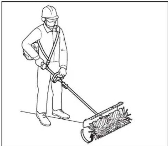
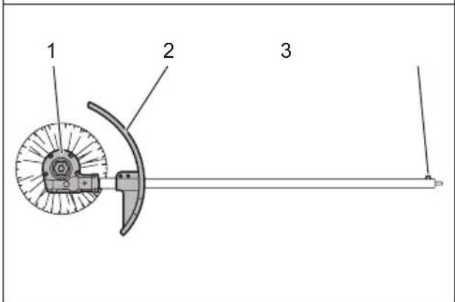
▶ 1. Cap 2. Pipe 3. Protector 4. Clip 5. Brush 6. Gear case 7. Hexalobular wrench
Power sweep attachment
▶ 1. Cap 2. Pipe 3. Protector 4. Clip 5. Sweep drum 6. Gear case 7. Hexalobular wrench
ASSEMBLY
WARNING: Before assembling or adjusting the equipment, switch off the motor or engine and remove the spark plug cap or battery cartridge. Otherwise the brushes, drums, or other parts may move and result in serious injury.
WARNING: When assembling or adjusting the equipment, always put it down. Assembling or adjusting the equipment in an upright position may result in serious injury.
WARNING: Follow the warnings and precautions in the chapter "SAFETY WARNINGS" and the instruction manual of the power unit.
Assembling the attachment
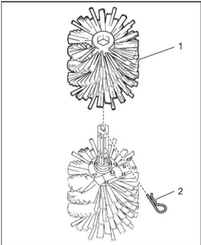
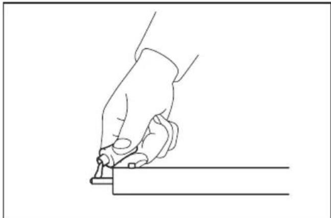
- Remove the clip from the brush or sweep drum on the left side of the brush unit or sweep drum unit, and then remove the brush or sweep drum.

▶ 1. Brush 2. Clip
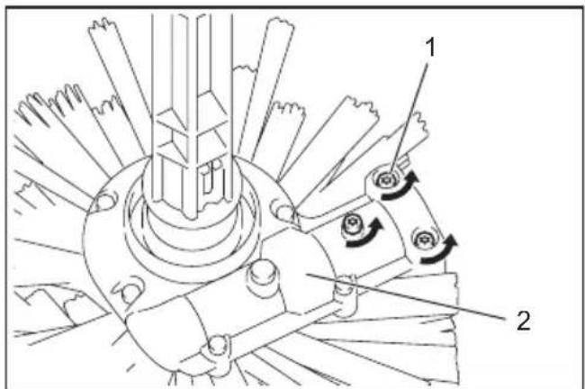
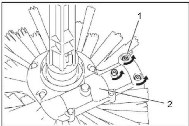
- Loosen 3 screws on the gear case.
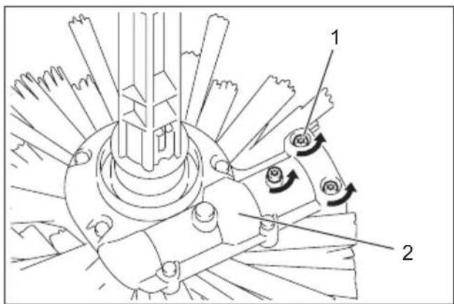
▶ 1. Screw 2. Gear case
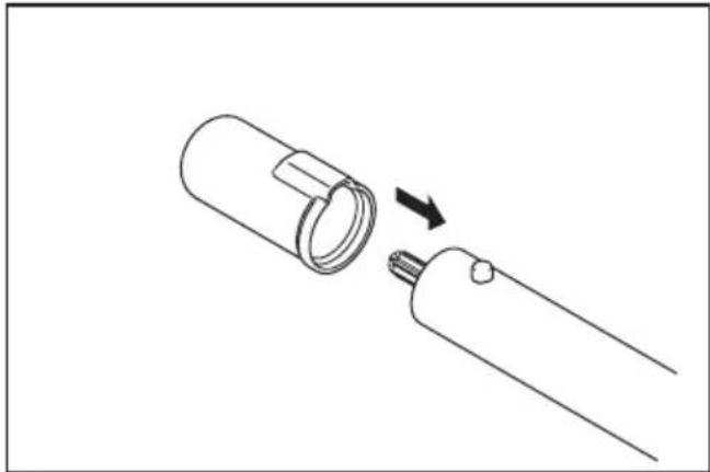
- Remove 2 caps from both ends of the pipe.
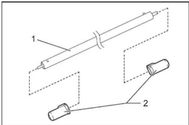
▶ 1. Pipe 2. Cap
NOTICE: Do not dispose of the caps since the cap is necessary for storing the attachment.
- Attach the protector and the sleeve to the pipe.
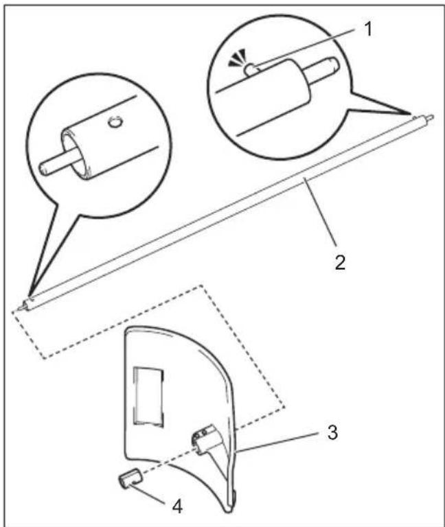
▶ 1. Pin 2. Pipe 3. Protector 4. Sleeve
NOTICE: Be sure to insert the end of the pipe without the pin into the protector and the sleeve.
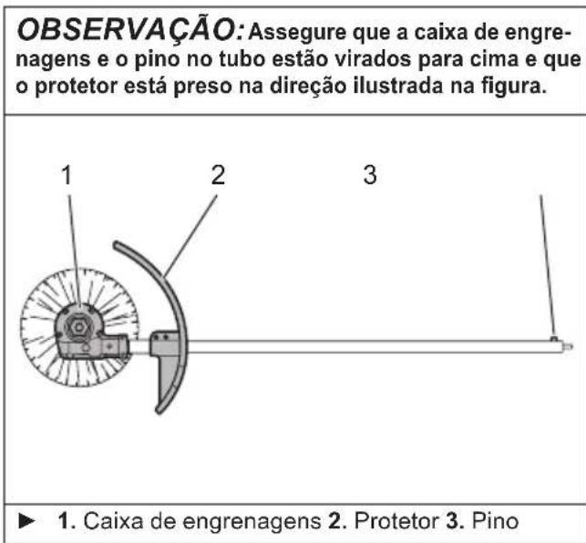
- Make sure that the gear case and the pin on the pipe are facing up, and then insert the pipe into the gear case.
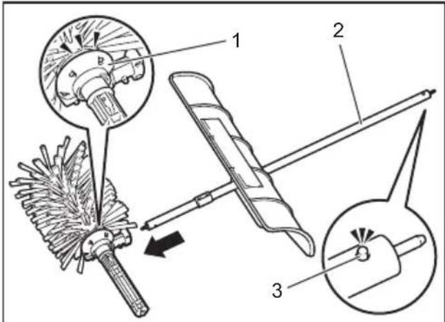
▶ 1. Gear case 2. Pipe 3. Pin
NOTICE: Make sure that the gear case and the pin on the pipe are facing up, and the protector is attached in the direction shown in the figure.
▶ 1. Gear case 2. Protector 3. Pin
- Align the screw hole on the pipe with the hole on the gear case by rotating the pipe.
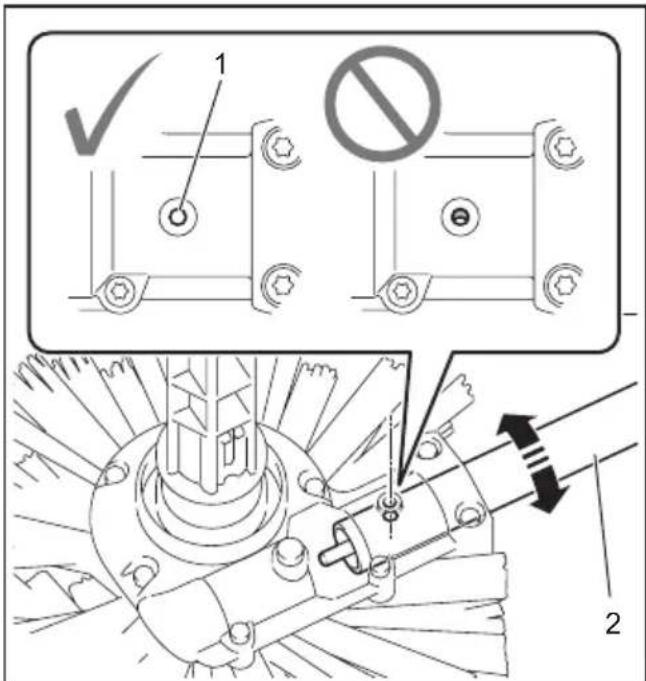
▶ 1. Hole 2. Pipe
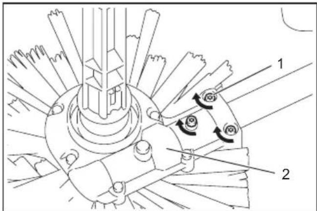
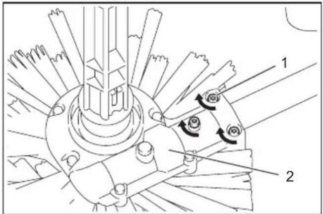
- Tighten 3 screws on the gear case.

▶ 1. Screw 2. Gear case
- Tighten 2 screws on the protector.
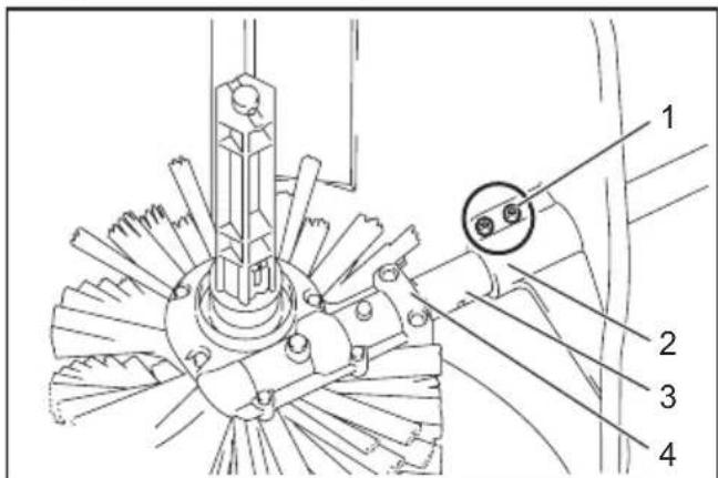
▶ 1. Screw 2. Protector 3. Sleeve 4. Gear case
NOTICE: Make sure that there is no gap between the gear case and the sleeve, and the sleeve and the protector.
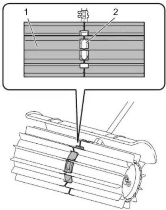
- Attach the brush or sweep drum to the brush unit or sweep drum unit, and then attach the clip to the brush or sweep drum.
NOTICE: When attaching the brushes, be sure to attach them with the Makita logo facing outside.
NOTICE: When attaching the sweep drums, be sure to attach them in the direction shown in the figure, so that the sweep drums and the gear case mesh with each other.
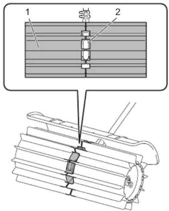
▶ 1. Sweep drum 2. Gear case
Mounting the attachment pipe
⚠️CAUTION: Always check that the attachment pipe is secured after installation. Improper installation may cause the attachment falling off from the power unit and cause personal injury.
Mount the attachment pipe to the power unit.
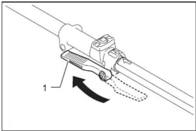
- Turn the lever toward the attachment.

▶ 1. Lever
- Align the pin with the arrow mark. Insert the attachment pipe until the release button pops up. Make sure that the position line is on the tip of the arrow mark.
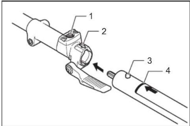
▶ 1. Release button 2. Arrow mark 3. Pin 4. Position line
- Turn the lever toward the power unit.
- Lever
Make sure that the surface of the lever is parallel to the pipe.
NOTICE: Do not tighten the lever without the attachment pipe inserted. Otherwise the lever may tighten the entrance of the drive shaft too much and damage it.
To remove the pipe, turn the lever toward the attachment and pull the pipe out while pressing down the release button.
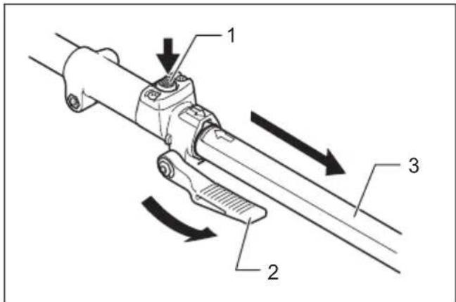
▶ 1. Release button 2. Lever 3. Pipe
OPERATION
WARNING: Follow the warnings and precautions in the chapter "SAFETY WARNINGS" and the instruction manual of the power unit.
WARNING: Adjust the hanger position and shoulder harness to your comfortable position before operating.
WARNING: Wear dust mask and well ventilate the work area. Some material contains chemicals which may be toxic. Take caution to prevent dust inhalation and skin contact.
CAUTION: Before operation, remove hard and/or long objects such as stones, cans, and ropes from the working area. They may damage the brushes or sweep drums or hinder the rotation of the brushes or sweep drums.
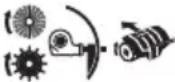
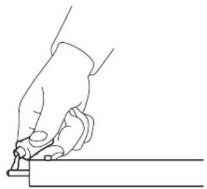
If the surface to be cleaned is dry, spray it with water to reduce the dust. Hold the power brush / power sweep at a shallow angle, and push the power brush / power sweep at walking speed.
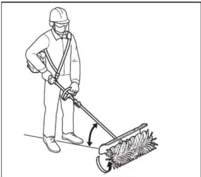
⚠️CAUTION: The steeper the angle becomes, the more difficult it is to control the power brush / power sweep, and the more likely you are pushed back by the power brush / power sweep.
MAINTENANCE
WARNING: Before inspecting or maintaining the equipment, switch off the motor and remove the spark plug cap or battery cartridge. Otherwise the brush, sweep drum, or other parts may move and result in serious injury.
WARNING: When inspecting or maintaining the equipment, always put it down. Assembling or adjusting the equipment in an upright position may result in serious injury.
WARNING: Follow the warnings and precautions in the chapter "SAFETY WARNINGS" and the instruction manual of the power unit.
NOTICE: Never use gasoline, benzine, thinner, alcohol or the like. Discoloration, deformation or cracks may result.
To maintain product SAFETY and RELIABILITY, repairs, any other maintenance or adjustment should be performed by Makita Authorized or Factory Service Centers, always using Makita replacement parts.
Cleaning the attachment
The attachment can be washed with water. Use a nylon brush or the similar to wash off dirt.

▶ 1. Power unit 2. Pipe end 3. Gear case
NOTICE: Do not pour water over the power unit and pipe end. It may cause a malfunction of the attachment.
For ease of cleaning, you can remove the brush or sweep drum from the brush unit or sweep drum unit. Refer to the instructions for replacing the brushes or sweep drums in this manual.
Overall inspection
- Tighten loose bolts, nuts and screws.
- Check for damaged parts, brushes, or sweep drums. Ask our authorized service center to replace them if necessary.
Inspecting the brushes, sweep drums, and protector
Check and clean the brushes, sweep drums, and protector daily. If they are worn, bent and cracked, replace them.
Replacing the brushes or sweep drums
- Remove the clips from the brushes or sweep drums, and then remove the brushes or sweep drums.
▶ 1. Brush 2. Clip
- Attach the brushes or sweep drums to the brush unit or sweep drum unit, and then attach the clips.
NOTICE: When attaching the brushes, be sure to attach them with the Makita logo facing outside.
NOTICE: When attaching the sweep drums, be sure to attach them in the direction shown in the figure, so that the sweep drums and the gear case mesh with each other.
▶ 1. Sweep drum 2. Gear case
Lubricating moving parts
NOTICE: Follow the instruction of the frequency and amount of grease supplied. Otherwise insufficient lubrication may damage moving parts.
Gear case:
⚠️ CAUTION: Do not apply grease when the gear case is hot. Hot gear case can cause burn injury.
Fill approx. 30 ml of grease (Makita grease SG No.0) through the grease port evenly every 25 hours of operation.
With the supplied hexalobular wrench, remove the bolt near the lubrication marking on the gear case. Loosen the bolt on the other side so that the air in the gear case can be released when applying the grease.
After applying the grease, be sure to tighten the bolts.
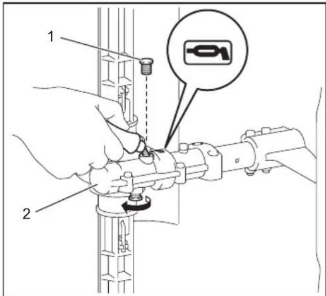
▶ 1. Bolt 2. Gear case
Drive axle:
Apply grease (Makita grease SG No.0) every 25 hours of operation.

NOTE: Genuine Makita grease may be purchased from your local Makita dealer.
Storage
WARNING: Follow the warnings and precautions in the chapter "SAFETY WARNINGS" and the instruction manual of the power unit.
When storing the attachment separated from the power unit, put the cap onto the end of the shaft.
Interval of inspection and maintenance
| Operating hour Before | Operation | Daily (10h) 25h | ||
| Whole unit Visually inspect for damaged parts | [25VZ] | - | - | |
| All fixing screws and nuts Tighten | [7H50] | - | - | |
| Brushes, sweep drums, and protector | Clean and visually inspect for damaged parts | - |  | - |
| Gear case Supply grease -- |  | |||
| Drive axle Supply grease -- |  | |||
| Power unit Refer to the instruction manual of the power unit | ||||
TROUBLESHOOTING
Before asking for repairs, conduct your own inspection first. If you find a problem that is not explained in the manual, do not attempt to dismantle the machine. Instead, ask Makita Authorized Service Centers, always using Makita replacement parts for repairs.
| State of abnormality Probable cause | (malfunction) Remedy | |
| Motor or engine does not start. - Refer to the instruction manual of the power unit. | ||
| Motor or engine stops soon. - Refer to the instruction manual of the power unit. | ||
| Motor or engine speed does not increase. | - Refer to the instruction manual of the power unit. | |
| Brushes or sweep drums do not rotate.⇒ Stop the motor or engine immediately. | The pipes of the power unit and the attachment are not connected properly. | Connect the pipes in the correct way. |
| Brushes or sweep drums caught a foreign matter. | Remove the foreign matter. | |
| Abnormal drive system Contact an authorized service center for repairs. | ||
| Power unit vibrates abnormally.⇒ Stop the motor or engine immediately. | Brushes or sweep drums are bent or broken. | Replace the brushes or sweep drums. |
| Loose attachment of the brushes or sweep drums | Attach the clips for the brushes or sweep drums securely. | |
| Irregular attachment of the brushes or sweep drums | Install the brushes or sweep drums in the correct way. | |
| Abnormal drive system Contact an authorized service center for repairs. | ||
| Brushes or sweep drums continue to rotate even if the switch trigger/lever is released.⇒ Stop the motor or engine immediately. | The power unit does not work properly. | Adjust the idle speed if the power unit is engine-operated. Contact an authorized service center for repairs. |
SPÉCIFICATIONS
▶ 1. Brosse 2. Attache
▶ 1. Tuyau 2. Capuchon
▶ 1. Trou 2. Tuyau
- Levier
▶ 1. Brosse 2. Attache
▶ 1. Bürste 2. Klammer
▶ 1. Rohr 2. Kappe
▶ 1. Stift 2. Rohr 3. Schutzhaube 4. Hülse
▶ 1. Hebel
▶ 1. Hebel
▶ 1. Spazzolone rotativo 2. Copiglia elastica
▶ 1. Leva
▶ 1. Leva
▶ 1. Spazzolone rotativo 2. Copiglia elastica
VEILIGHEIDSWAAR- SCHUWINGEN
- Dop 2. Pijp 3. Beschermkap 4. Klem 5. Borstel 6. Tandwielhuis 7. Torxsleutel
Vegerhulpstuk

- Dop 2. Pijp 3. Beschermkap 4. Klem 5. Veegtrommel 6. Tandwielhuis 7. Torxsleutel
MONTAGE
▶ 1. Borstel 2. Klem
▶ 1. Schroef 2. Tandwielhuis
▶ 1. Pijp 2. Dop
▶ 1. Pen 2. Pijp 3. Beschermkap 4. Bus
▶ 1. Tandwielhuis 2. Pijp 3. Pen
▶ 1. Gat 2. Pijp
▶ 1. Schroef 2. Tandwielhuis
- Schroef 2. Beschermkap 3. Bus 4. Tandwielhuis
▶ 1. Veegtrommel 2. Tandwielhuis
▶ 1. Hendel
- Hendel
▶ 1. Ontgrendelknop 2. Hendel 3. Pijp
BEDIENING
▶ 1. Borstel 2. Klem
▶ 1. Veegtrommel 2. Tandwielhuis
▶ 1. Bout 2. Tandwielhuis
Aandrijfas:
Persona responsible: Kazuhisa Makino, Director - Makita Europe N.V.

- Tapa 2. Tubo 3. Protector 4. Clip 5. Cepillo 6. Caja de engranajes 7. Llave hexalobular
▶ 1. Tapa 2. Tubo 3. Protector 4. Clip 5. Tambor barredor 6. Caja de engranajes 7. Llave hexalobular
MONTAJE
▶ 1. Tornillo 2. Caja de engranajes
▶ 1. Tubo 2. Tapa
▶ 1. Pasador 2. Tubo 3. Protector 4. Manguito
▶ 1. Orificio 2. Tubo
▶ 1. Tornillo 2. Caja de engranajes
- Tornillo 2. Protector 3. Manguito 4. Caja de engranajes
▶ 1. Tambor barredor 2. Caja de engranajes
- Palanca
▶ 1. Tambor barredor 2. Caja de engranajes
▶ 1. Perno 2. Caja de engranajes
Eje propulsor:
▶ 1. Tampa 2. Tubo 3. Protetor 4. Clipe 5. Escova 6. Caixa de engrenagens 7. Chave hexalobular
▶ 1. Tampa 2. Tubo 3. Protetor 4. Clipe 5. Cilindro de varrer 6. Caixa de engrenagens 7. Chave hexalobular
MONTAGEM
▶ 1. Tubo 2. Tampa
▶ 1. Pino 2. Tubo 3. Protetor 4. Manga
- Caixa de engrenagens 2. Tubo 3. Pino
- Parafuso 2. Protetor 3. Manga 4. Caixa de engrenagens
▶ 1. Cilindro de varrer 2. Caixa de engrenagens
- Alavanca
▶ 1. Cilindro de varrer 2. Caixa de engrenagens
-
Børste 2. Klemme
-
Løsn 3 skruer på gearhuset.
▶ 1. Skrue 2. Gearhus
- Rør 2. Hætte
-
Hul 2. Rør
-
Stram 3 skruer på gearhuset.
▶ 1. Skrue 2. Gearhus
▶ 1. Fejetromle 2. Gearhus
- Håndtag
▶ 1. Fejetromle 2. Gearhus
▶ 1. Bolt 2. Gearhus
Drevaksel:
Tilfør fedtstof (Makita fedtstof SG No.0) for hver 25 timers drift.
Interval for inspektion og vedligeholdelse
- Σωλήνας 2. Καπάκι
▶ 1. Οπή 2. Σωλήνας
- Bída 2. Prostatetikó 3. Xitwivio 4. Kiβwtio obovtwtów troxwv
- Μοχλός
▶ 1. Fırça 2. Firkete
- Boru 2. Başlık
- Pim 2. Boru 3. Koruyucu 4. Manşon
▶ 1. Delik 2. Boru
- Mandal
▶ 1. Fırça 2. Firkete
▶ 1. 研光刷 2. 固定夾
- 鬷開齒輪箱上的 3 顆螺絲。
▶ 1. 螺絲 2. 齒輪箱
- 取下外管兩端的 2 個蓋子。

▶ 1. 外管 2. 蓋子
▶ 1. 開孔 2. 外管
- 鎖緊齒輪箱上的 3 顆螺絲。
▶ 1. 螺絲 2. 齒輪箱
- 鎖緊安全保護裝置上的 2 顆螺絲。

▶ 1. 掃除刀筒 2. 齒輪箱
安裝連接管
▶ 1. 固定桿
▶ 1. 固定桿
確認固定桿表面與連接管平行。
▶ 1. 研光刷 2. 固定夾
▶ 1. 掃除刀筒 2. 齒輪箱
潤滑移動部件
▶ 1. 螺栓 2. 齒輪箱
驅動軸:
檢查和保養間隔


- APPROVED POWER UNIT
- SYMBOLS
- INTENDED USE
- BR400MP
- SW400MP
- DECLARATIONS OF CONFORMITY
- FOR EUROPEAN COUNTRIES ONLY
- DECLARATION OF CONFORMITY (FOR UK)
- FOR UK ONLY
- SAFETY WARNINGS
- POWER BRUSH / POWER SWEEP SAFETY WARNINGS
- SAVE ALL WARNINGS AND INSTRUCTIONS FOR FUTURE REFERENCE
- GENERAL SAFETY
- WORK AREA SAFETY
- PERSONAL PROTECTIVE EQUIPMENT
- REFUELING
- STARTING UP THE POWER BRUSH / POWER SWEEP
- TRANSPORTATION
- OPERATION
- VIBRATION
- MAINTENANCE
- STORAGE
- FIRST AID
- SAVE THESE INSTRUCTIONS
- PARTS DESCRIPTION
- POWER BRUSH ATTACHMENT
- POWER SWEEP ATTACHMENT
- ASSEMBLY
- ASSEMBLING THE ATTACHMENT
- MOUNTING THE ATTACHMENT PIPE
- CLEANING THE ATTACHMENT
- OVERALL INSPECTION
- INSPECTING THE BRUSHES, SWEEP DRUMS, AND PROTECTOR
- REPLACING THE BRUSHES OR SWEEP DRUMS
- LUBRICATING MOVING PARTS
- GEAR CASE
- DRIVE AXLE
- TROUBLESHOOTING
- VEILIGHEIDSWAAR- SCHUWINGEN
- VEGERHULPSTUK
- MONTAGE
- BEDIENING
- AANDRIJFAS
- MONTAJE
- EJE PROPULSOR
- MONTAGEM
- DREVAKSEL
- 安裝連接管
- 潤滑移動部件
- 驅動軸:
Brand : MAKITA
Model : 1993397
Category : Multifunction tool