
AS3200 - Home cinema amp YAMAHA - Free user manual and instructions
Find the device manual for free AS3200 YAMAHA in PDF.
| Features | Details |
|---|---|
| Product type | Stereo audio receiver |
| Output power | 2 x 160 W (8 ohms) |
| Impedance | 4 to 16 ohms |
| Connectivity | RCA inputs, digital inputs, Bluetooth |
| Audio features | Compatible with high-resolution audio formats |
| Dimensions | 435 x 151 x 400 mm |
| Weight | 15 kg |
| Recommended use | For high-quality music listening at home |
| Maintenance | Regularly clean contacts and inputs |
| Safety | Do not expose to moisture, use with compatible speakers |
| Additional information | 2-year warranty, technical support available |
Frequently Asked Questions - AS3200 YAMAHA
User questions about AS3200 YAMAHA
0 question about this device. Answer the ones you know or ask your own.
Ask a new question about this device
Download the instructions for your Home cinema amp in PDF format for free! Find your manual AS3200 - YAMAHA and take your electronic device back in hand. On this page are published all the documents necessary for the use of your device. AS3200 by YAMAHA.
USER MANUAL AS3200 YAMAHA
Integrated Amplifier
PykoBoDCTBO NOIb3OBaTeJIa
Thank you and congratulations on your purchase of this Yamaha product.
- You can enjoy the high-quality stereo sound of this integrated amplifier at home.
- To use the product properly and safely, we suggest that you read this manual and the "Safety Brochure" thoroughly. Keep the manual in a safe, accessible place for future reference.
Features
Floating balanced circuit for power amplifier
Fully-balanced transmission from input to output
Tone control circuit with a parallel volume system
Large power supply with four separate circuits
Left-right symmetrical design
Fully discrete phono amp
Low-impedance, high-performance headphone amp
High-rigidity lever selectors
Things to know before using this product
About this manual
- This manual describes the unit's features and connection procedures.
- The illustrations as shown in this manual are for instructional purposes only.
- Specifications and appearance are subject to change without notice.
WARNING" describes precautions to be followed to avoid the possibility of serious injury or even death.
CAUTION" describes precautions to be followed to avoid injury.
- "NOTICE" describes precautions to be followed to avoid malfunction or damage to the product.
- “” deNotes supplemental information about the product.
Supplied accessories
Please make sure that the following accessories are included in the package.
- Remote control
- Batteries (AAA, R03, UM-4) (× 2)
- Power cable*
- Owner's Manual (this book)
-
Safety Brochure
-
Multiple power cables might be included in the package depending on the area of distribution. Please use the one that is appropriate for your AC outlet.
Table of Contents
Features. 3
Things to know before using this product.. 4
About this manual. 4
Supplied accessories. 4
Part Names and Functions 5
Front panel. 6
Rear panel 10
Remote control. 12 Installing batteries in the remote control... 14
Operating the remote control. 14
Connections 15
Connection diagram 16
Connecting speakers 18
Using speaker cables 18
Using banana plug cables. 19
Using Y-shaped lug cables. 19
Bi-wired connection 19
Balanced connection. 20
Trigger connection 20
Remote connection. 21
Operating the unit from another room....21
Remote connection between
Yamaha components. 21
Connecting the power cable. 22
Appendix. 23
Specifications. 24
Block diagram. 26
Acoustic characteristics. 27
Tone control characteristics 27
Total harmonic distortion 27
Total harmonic distortion (PHONO) 28
Troubleshooting 29
Maintenance. 30
Part Names and Functions
This section lists the names and describes the function of various parts on the front and rear panels, and the remote control.
Part Names and Functions
Front panel
YAMAHA

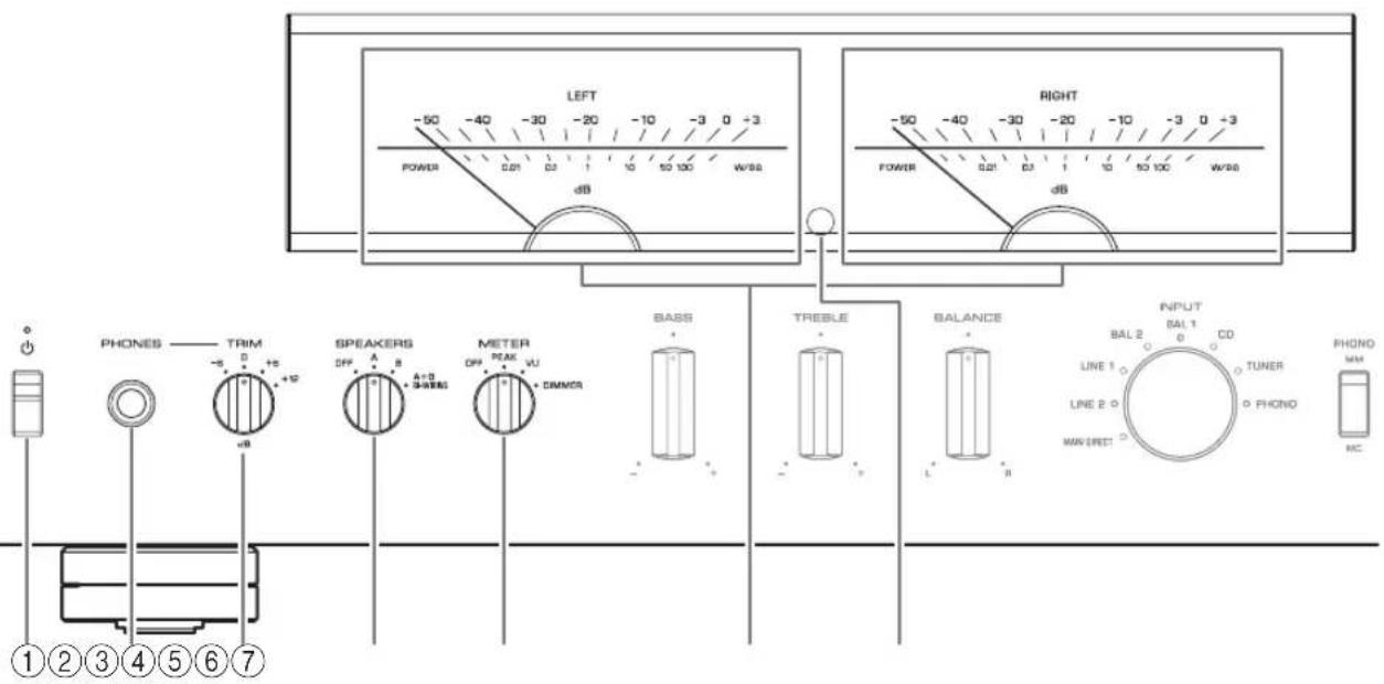
① (Power) switch/indicator
| (Power) switch | Power status Indicator | |
| Up position | On Lit brightly | |
| Standby Lit dimly | ||
| Down position Off | Off | |
While the (Power) switch is in the up position, press the AMP key on the remote control repeatedly to switch the power to the unit between on and standby mode. In addition, under either of the following conditions, the unit will enter standby mode.
If the Auto Power Standby function is enabled. ( page 10)
- If you turn off the power to a device that has been set to trigger connection to this unit. ( page 20)
NOTICE
If you plan not to use the unit for an extended period of time, be sure to unplug the power plug from the AC outlet. Even when the power is turned off, a minimal amount of electric current is still flowing to the unit.
Note
After you turn on the unit, it will take a few seconds before the unit can reproduce sound.
- Do not turn on the power to this unit again within 10 seconds after the power has been turned off. Doing so may generate noise.
- While the unit is in standby mode, to turn on power to the unit first set the (Power) switch to the down position to turn the power off, then set the switch to the up position.
②PHONESjack
Connect your headphones here.
Note
- Connecting the headphones here will result in the following:
- No sound will be heard from the connected speakers.
- Audio signals will not be output at the PRE OUT jacks.
- You will be unable to select MAIN DIRECT as the input source.
- If MAIN DIRECT is selected as the input source, audio signals will not be output at the PHONES jack.
③TRIM selector
Switches the headphone amp gain.
Select the gain setting that is appropriate for your headphones.
Available gain:
-6dB,0dB,+6dB,+12dB
④SPEAKERS selector
Switches sets of speakers connected to the SPEAKERS L/R CH A and B terminals on the rear panel as follows:
OFF: No audio signals will be output from the speakers.
A: Audio signals will be output from the set of speakers connected to the A terminals.
B: Audio signals will be output from the set of speakers connected to the B terminals.
A+B BI-WIRING: Audio signals will be output from the sets of speakers connected to the A and B terminals. Select this position when you plan to make a bi-wired connection. ( page 19)
NOTICE
If you connect two sets of speakers (A + B) use the speakers with an impedance of 8 or higher.
⑤METER selector
Switches the meter function as follows:
OFF: Turns off meter operation and display illumination.
PEAK: Switches the meter display type to a peak level meter. The peak level meter shows the highest instantaneous level of an audio output signal.
VU: Switches the meter display type to a VU (Volume Unit) level meter. The VU level meter shows an effective audio output value that represents the way sound is perceived by human ears.
DIMMER: When selected, the DIMMER automatically changes the brightness of the meter display in steps. When you see the brightness level you desire, switch to another setting parameter to lock in the new brightness setting.
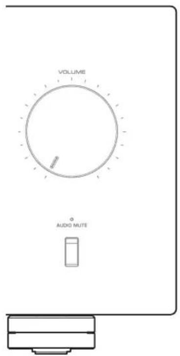
⑥Meter (LEFT/RIGHT)
Indicates the audio output level of the left (LEFT) and right (RIGHT) channels.
Remote control sensor
Receives signals from the remote control. ( page 14)
Part Names and Functions
Front panel
YAMAHA
BASS control
Adjusts the volume level of the bass range.
Adjustable range: -10dB - 0 + 10dB
⑨TREBLE control
Adjusts the volume level of the treble range.
Adjustable range: -10dB - 0 + + 10dB
10BALANCE control
Adjusts the audio output balance between the left and right speakers to compensate for sound imbalances caused by speaker locations or listening room conditions.
Note
- If both BASS and TREBLE controls are set to 0 (zero), the audio signal will bypass the tone control circuit.
- The BASS, TREBLE, and BALANCE control settings will not affect the input signals at the MAIN IN jacks nor the output signals at the LINE 2 OUT jacks.
⑪INPUT selector/indicator
Selects the input source. The indicator for the selected input source lights up. Audio signals of the selected input source will be output at the LINE 2 OUT jacks.
MAIN DIRECT: Selects the component connected to the MAIN IN jacks as the input source.
LINE 1/LINE 2: Selects the component connected to the LINE 1 or LINE 2 jacks as the input source.
BAL 1/BAL 2: Selects the component connected to the BAL 1 or BAL 2 input jacks as the input source.
CD: Selects the CD player connected to the CD input jacks as the input source.
TUNER: Selects the tuner connected to the TUNER input jacks as the input source.
PHONO: Selects the turntable connected to the PHONO input jacks as the input source.
Note
- If MAIN DIRECT is selected as the input source, audio signals will not be output at the PRE OUT, LINE 2 OUT or PHONES jacks.
- If LINE 2 is selected, audio signals will not be output at the LINE 2 OUT jacks.
⑫PHONO switch
Set this switch to the MM or MC position according to the type of magnetic cartridge of the turntable connected to the PHONO input jacks on the rear panel.
Note
Before you replace the cartridge for the turntable, be sure to turn off the power to this unit.
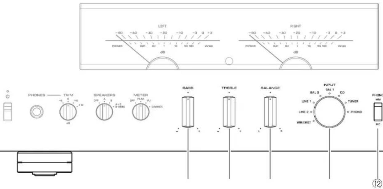
⑬Feet
If the unit is unstable, adjust the height of the feet as needed by rotating them.
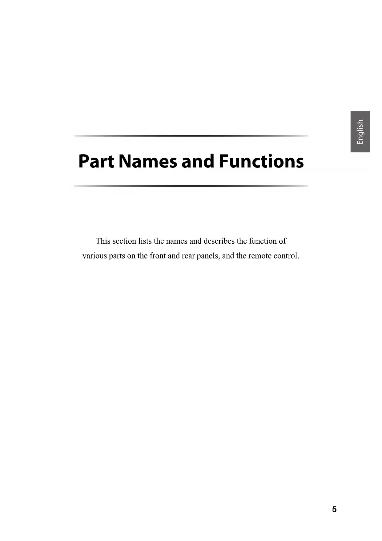
14 AUDIO MUTE switch/indicator
Press this switch to reduce the current volume level by approximately 20 dB. The indicator will light up. Press again to restore the audio output to the previous volume level. The indicator will turn off.
15VOLUME knob
Adjusts the volume level. This setting will not affect the output level at the LINE 2 OUT jacks.
NOTICE
If you select MAIN DIRECT as the input source for this unit, the volume level will be fixed. In this case, to adjust the volume level, use the volume control on the external amplifier connected to the MAIN IN jacks.
Part Names and Functions
Rear panel

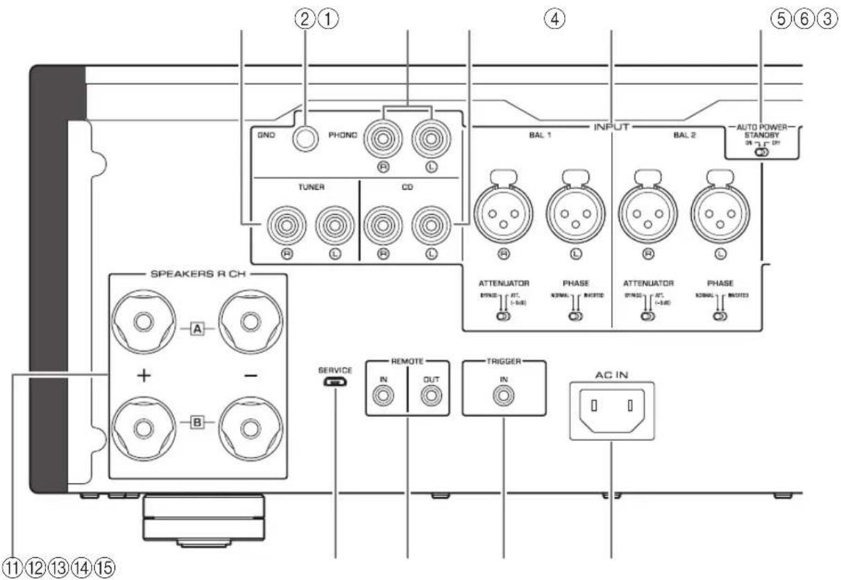
①TUNER input jacks
② GND (Ground) terminal
If you connect your turntable to this unit, ground it to the GND terminal. Doing so may reduce noise.

CAUTION
Do not loosen the GND terminal knob excessively. Otherwise, the knob may come off and a child may swallow it accidentally.
Note
This is not a safety ground.
③PHONO input jacks
④CD input jacks
⑤BAL 1/BAL 2 (balanced) input jacks
Note
Set the ATTENUATOR selector and PHASE selector appropriately for the playback components that are connected to the unit. () page 20
⑥ AUTO POWER STANDBY switch
ON: The unit enters standby mode automatically if it is left turned on and not operated for eight hours (Auto Power Standby function).
OFF: The unit does not enter standby mode automatically.
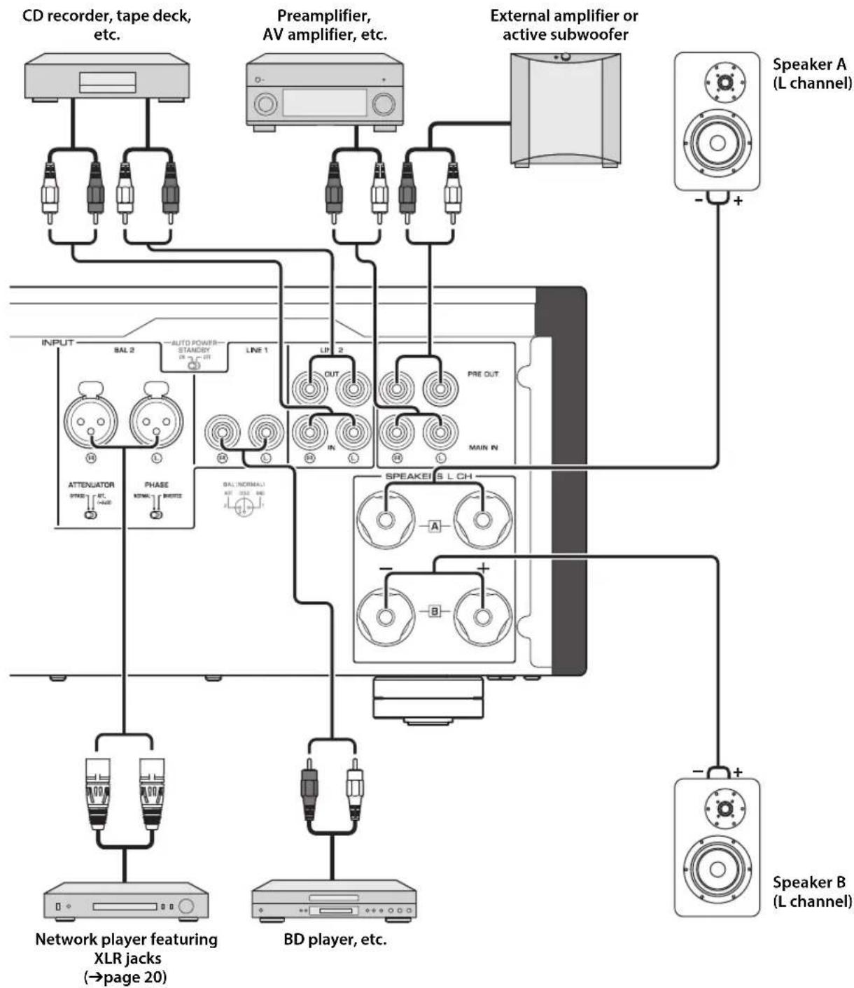
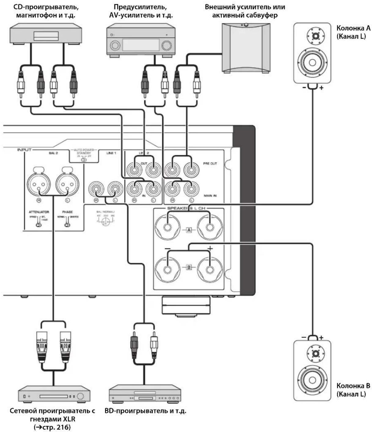
LINE1inputjacks
⑧LINE 2 jacks
Connect external components that feature analog audio in/out jacks.
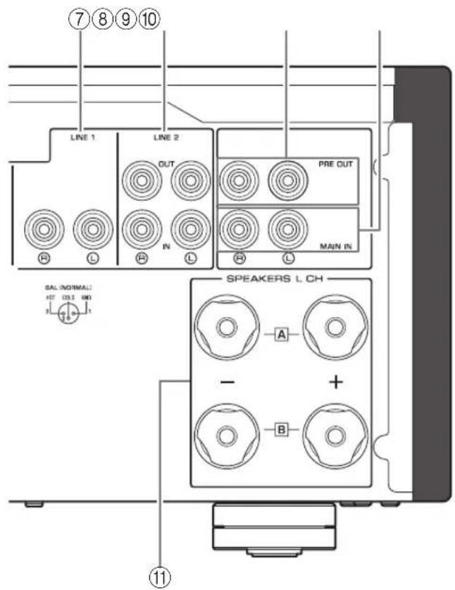
PRE OUT jacks
Note
- Audio signals output at the PRE OUT jacks are the same channel signals that are output at the SPEAKERS L/R CH terminals.
The following parameter settings are effective for audio signals output at the PRE OUT jacks.
-BASS
-TREBLE
-BALANCE
VOLUME
10MAIN IN jacks
Connect external components that feature a volume control function so that you can use this unit as a power amplifier.
NOTICE
If you select MAIN DIRECT as the input source for this unit, the volume level will be fixed. In this case, to adjust the volume level, use the volume control on the external amplifier connected to the MAIN IN jacks.
11SPEAKERS L/R CH terminals
⑫ SERVICE jack
This jack is used to test the product.
⑬REMOTE IN/OUT jacks
Connect external components that support the remote function. ( page 21)
14TRIGGER IN jack
Connect external components that support the trigger function. ( page 20)
15AC IN jack
Connect the supplied power cable here. ( page 22)
Part Names and Functions
Remote control
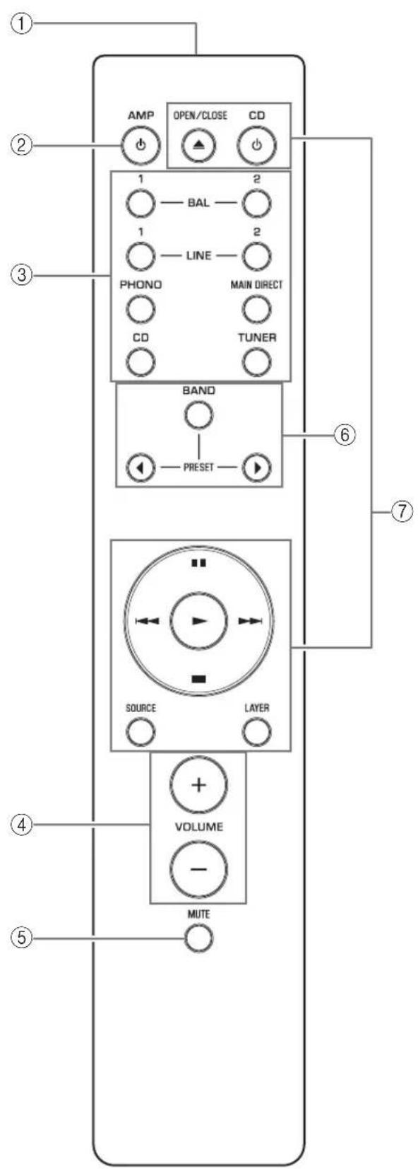
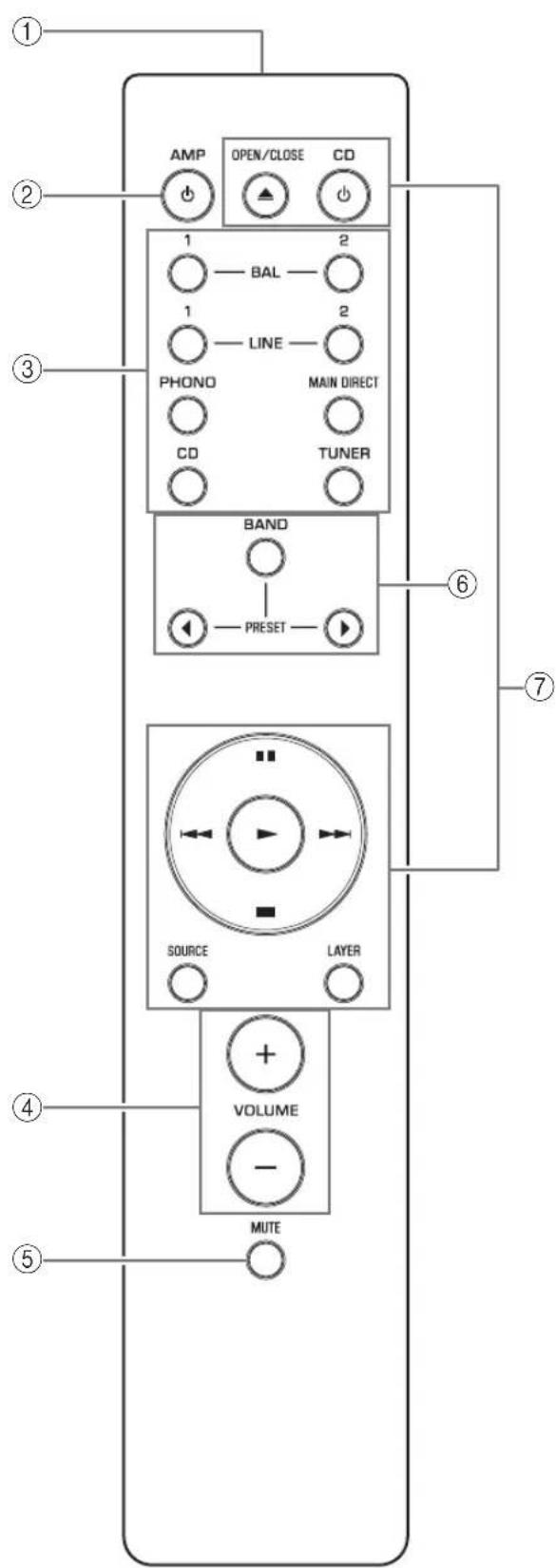
① Infrared signal transmitter
Outputs infrared control signals toward the unit. ( page 14)
② AMP key
Turns on the power to the unit or switches it to standby mode. ( page 6)
③Input select keys
Select the input source.
Audio signals of the selected input source will be output at the LINE 2 OUT jacks.
BAL 1/BAL 2: Selects the component connected to the BAL 1 or BAL 2 input jacks as the input source.
LINE 1/LINE 2: Selects the component connected to the LINE 1 or LINE 2 jacks as the input source.
PHONO: Selects the turntable connected to the PHONO input jacks as the input source.
MAIN DIRECT: Selects the component connected to the MAIN IN jacks as the input source.
CD: Selects the CD player connected to the CD input jacks as the input source.
TUNER: Selects the tuner connected to the TUNER input jacks as the input source.
Note
- If MAIN DIRECT is selected as the input source, audio signals will not be output at the PRE OUT, LINE 2 OUT or PHONES jacks.
- If LINE 2 is selected, audio signals will not be output at the LINE 2 OUT jacks.
④VOLUME+/-keys
Adjust the volume level. This setting will not affect the output level at the LINE 2 OUT jacks.
NOTICE
If you select MAIN DIRECT as the input source for this unit, the volume level will be fixed. In this case, to adjust the volume level, use the volume control on the external amplifier connected to the MAIN IN jacks.
⑤MUTEkey
Press this key to reduce the current volume level by approximately 20 dB. Press the key again to restore the previous volume level.
⑥ Tuner control keys
Control the functions of a connected Yamaha tuner. For more information, refer to the owner's manual for your tuner.
CD player control keys
Control the functions of a connected Yamaha CD player. For more information, refer to the owner's manual for your CD player.

OPEN/CLOSE key: Opens or closes the disc tray of a connected CD player.
CD key: Turns on the power to a connected CD player, or switches it to standby mode.
▶ (Play): Starts playback of the CD player.
(Pause): Pauses playback of the CD player. Press or tume playback.
(Stop): Stops playback of the CD player.
/ (Skip): Skips to the next track, or returns to the beginning of the current track.
SOURCE key: Selects the source to be played on the CD player. The playback source changes each time this key is pressed.
LAYER key: Toggles the playback layer of a hybrid super audio CD between "Super audio CD" and "CD."
Note
Some Yamaha tuners or CD players might not support the tuner or CD player control keys.
Part Names and Functions
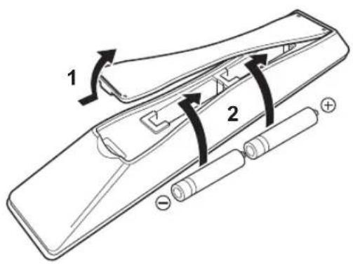
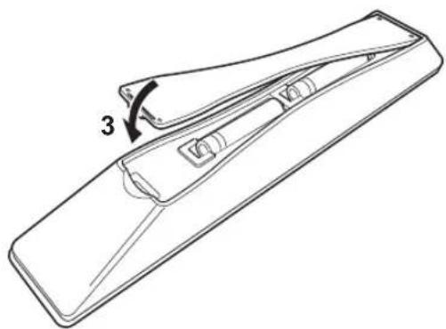
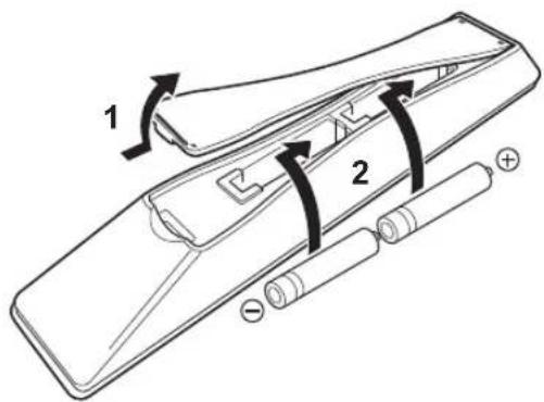
■Installing batteries in the remote control
1 Remove the battery compartment cover.
2Insert two batteries (AAA, R03, UM-4) according to the polarity markings (+ and -) on the inside of the battery compartment.
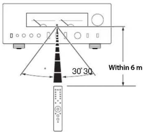
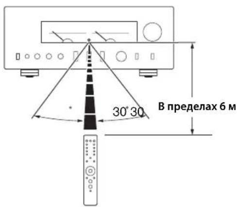
Operating the remote control
Operate the remote control in the range shown below by pointing it toward the remote control sensor on the front panel of the unit.
3Reinstall the battery compartment cover.
Connections
This section explains how to connect the unit to speakers and audio source components.
Connections
Connection diagram

CAUTION
Be sure to complete all connections before plugging in the power cable to an AC outlet. ( page 22)
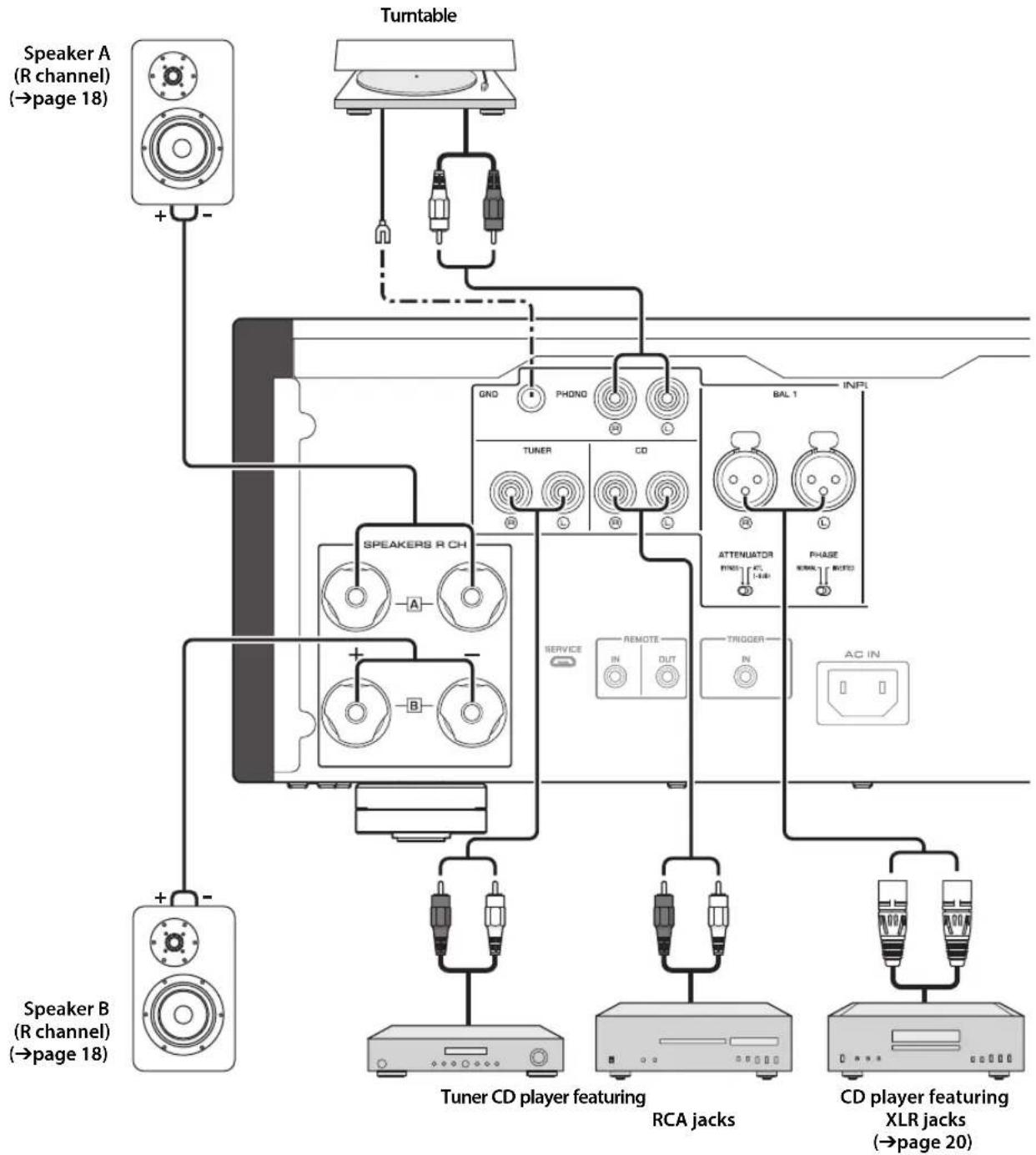
NOTICE
If a component is connected to the MAIN IN jacks, the unit's volume level will be fixed. Therefore, do not connect a CD player or other components that do not feature volume adjustment to the MAIN IN jacks. Otherwise, a loud sound may be emitted, resulting in malfunction of the unit or damage to the speakers.
Connections
Note
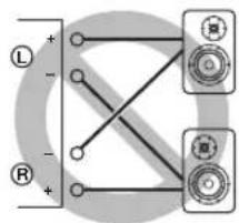
-
Because this power amplifier is of the floating balanced type, the following connections are not possible.
-
Connecting between two "+" (or two "-" terminals of the left and right channels (Fig. 1).
- Connecting each "--" terminal of the unit's left and right channels to the opposite channel speakers (cross connection, Fig. 2).
- Connecting the left/right channel " - " terminals (or accidentally allowing them to come in contact) with the metal part of the rear panel of this unit.
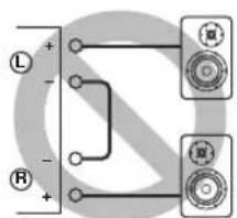
Figure 1
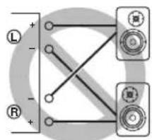
Figure 2
- Do not connect an active subwoofer to the SPEAKERS L/R CH terminals. Connect the subwoofer to the unit's PRE OUT jacks.
Connecting speakers
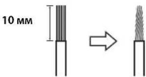
Using speaker cables
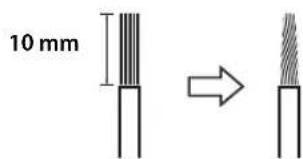
1 Remove approximately 10mm of insulation from the end of each speaker cable, and twist the exposed wires together tightly to prevent short circuits.
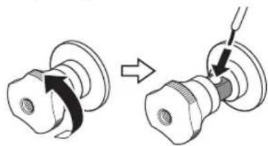
2Unscrew the knob on each speaker terminal, and then insert the bare wire into the side hole on the terminal.
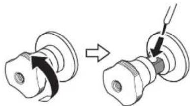
Diameter of the speaker cable wire hole: 6.0mm
3Tighten the knob.
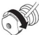

CAUTION
- Do not loosen the knob excessively. Otherwise, the knob may come off and a child may swallow it accidentally.
To reduce the risk of electric shock, do not touch the speaker terminals while the power to the unit on.
NOTICE
- If the SPEAKERS terminals come into contact with a metallic rack, a short circuit may occur, resulting in damage to this unit. When installing the unit in a rack, maintain a sufficient clearance to prevent the SPEAKERS terminals from coming into contact with the rack.
- Do not let the bare speaker wires touch each other, nor let them touch any metal part of this unit. Otherwise, the unit and/or the speakers may be damaged.
Note
All connections must be correct: L (left) to L, R (right) to R, "+" to "+" and "-" to "-" For information regarding the connection procedure, refer to the owner's manual for your speakers.
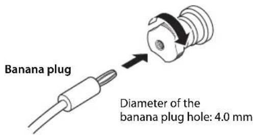
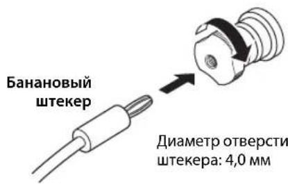
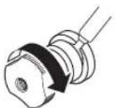
Using banana plug cables
(Models for U.S.A., Canada, Australia, China, and Taiwan)
First tighten the knob on the SPEAKERS terminal, and then insert the banana plug into the head of the knob.
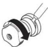
Using Y-shaped lug cables
1Unscrew the knob, and then sandwich the Y-shaped lug between the ring part and base of the terminal.
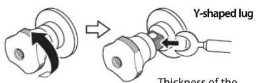
Thickness of the terminal core: 5.8mm
2Tighten the knob.
Bi-wired connection
A bi-wired connection separates the woofer from the mid and high ranges. Speakers that support bi-wired connection feature two pairs of terminals (total four terminals). These two pairs of terminals can divide the speakers into two independent parts. To make this kind of connection, you need to connect mid and high range drivers to one pair of terminals, and low range drivers to the other pair of terminals.
1 Remove the shorting bars or bridges on the speakers.
2Connect this unit to the speakers as shown in the figure below.
An example of left channel connection
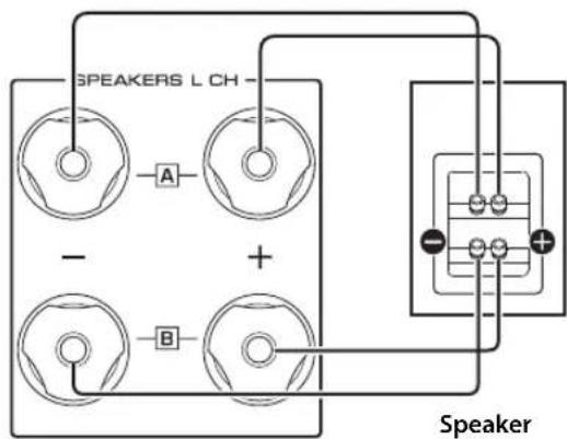
Rear panel of this unit
3Set the SPEAKERS selector on the front panel to A+B BI-WIRING.
Connections
Balanced connection
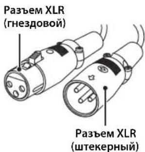
You can connect a CD player or network player that features XLR-type balanced output jacks to the BAL 1 or BAL 2 input jacks of this unit. Use XLR-type balanced cables for this connection.
ATTENUATOR selector: Enables you to set the allowable input level at the balanced input jacks. Select ATT. (-6dB) if the audio output from the connected component sounds distorted.
PHASE selector: Enables you to set the position (phase) of the HOT pin (pin #2: HOT or pin #3: HOT) at the balanced input jacks.
NORMAL
(Pin #2: HOT)
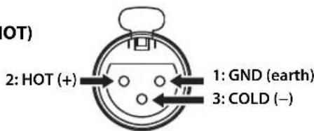
INV.
(Pin #3: HOT)
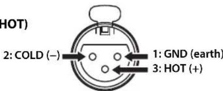
Refer to the instruction manual for the connected component to find out the position of the HOT pin at the balanced output jacks on the component.
Note
- Select NORMAL (pin #2 is HOT) for a Yamaha player.
- Do not use balanced and unbalanced connections for one component simultaneously. Doing so would create a ground loop that could generate static and noise.
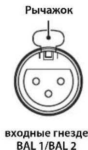
- When connecting a cable, be sure to align the pins on the connector with the holes on the jack, and then insert the male XLR connector into the jack until you hear a click. To remove the cable, while pressing and holding down the lever on the BAL 1 or BAL 2 input jack, pull out the male XLR connector from the jack.
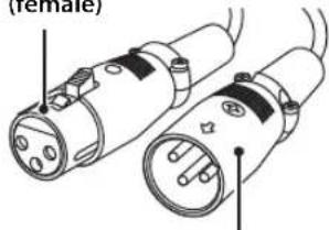
XLR connector
(female)
XLR connector
(male)
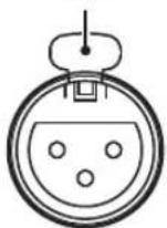
Lever
BAL 1/BAL 2
input jack
- For a balanced connection, select BAL 1 or BAL 2 as the input source.
Trigger connection
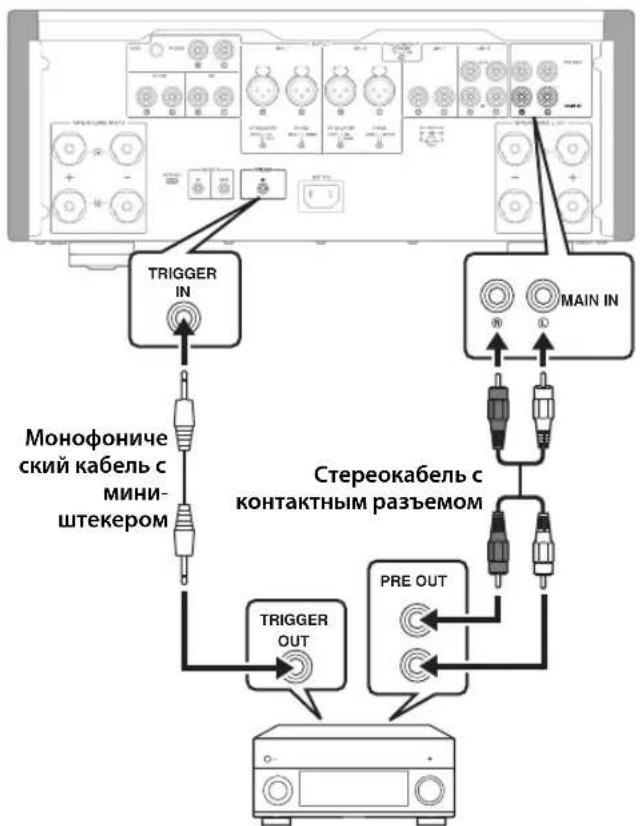
You can connect a Yamaha AV receiver or other component that supports the Trigger function. You can control this unit in sync with a connected component.
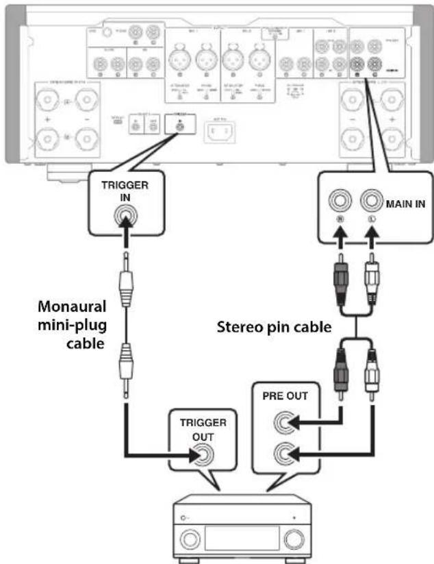
Rear panel of this unit
Yamaha AV receiver or
other component that features
TRIGGER OUT jacks and PRE OUT jacks
When the power to the connected component is turned on, the power to this unit is also turned on. Simultaneously, the input source to the unit is set to MAIN DIRECT. If MAIN DIRECT has been selected as the input source for this unit, when the power to the connected component is turned off, this unit will enter standby mode.
Note
When the power switch on this unit is turned Off, the power to the unit will not be triggered.
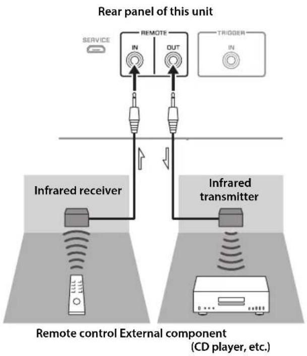
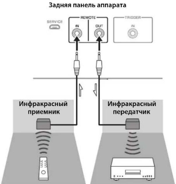
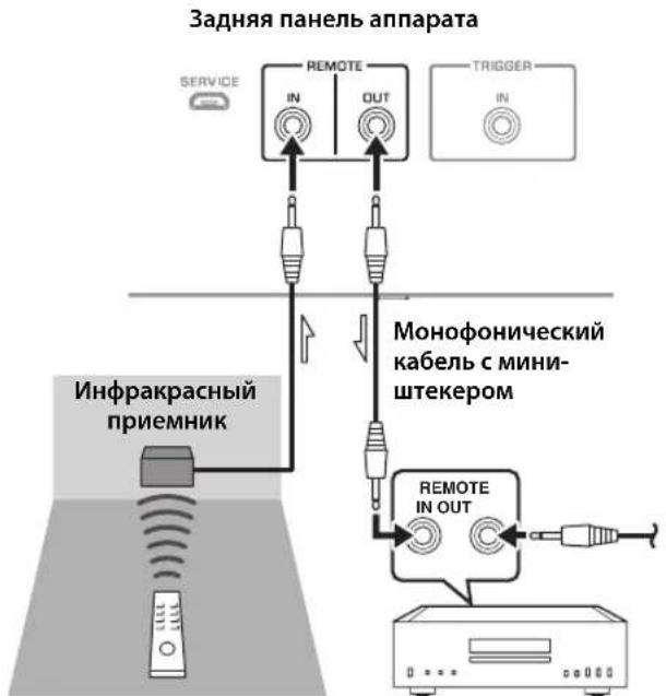
Remote connection
Operating the unit from another room
If you connect a commercially-available infrared receiver and transmitter to the unit's REMOTE IN/OUT jacks, you will be able to operate the unit and/or external component from another room, using the supplied remote control.
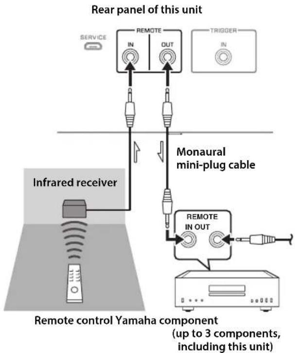
Remote connection between Yamaha components
If you have another Yamaha component that supports remote connections, an infrared transmitter is not necessary. Connect an infrared receiver to the unit's REMOTE IN/OUT jacks, as shown below.
Up to 3 Yamaha components (including this unit) can be set up for remote connection.
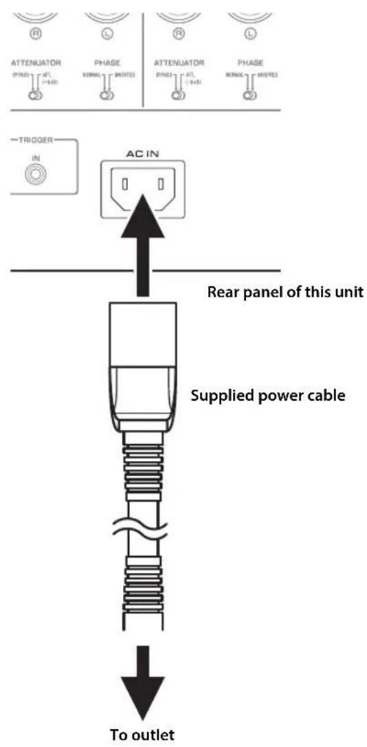
Connections
Connecting the power cable
After all connections are complete, plug the power cable into the AC IN connector of the unit, and then plug the power plug into the AC outlet.
Appendix
This section lists technical specifications for this unit.
Appendix
Specifications
Rated output power (20 Hz to 20 kHz, 0.07% THD)
2-channel driven
[Model for Asia]
8Ω 90W+90W
4Ω 145W+145W
[Other models]
8Ω 100W+100W
4Ω 150 W + 150 W
Dynamic power
[Model for Asia]
8Ω 100W+100W
6Ω 130W+130W
4Ω 180W+180W
2Ω 290W+290W
[Other models]
8Ω 120W+120W
6Ω 150W+150W
4Ω 200W+200W
2Ω 300W+300W
IEC output power (1 kHz, 0.07% THD)
[Models for U.K. and Europe]
8Ω 105W+105W
Maximum effective output power
(JEITA, 1 kHz, 10% THD)
[Model for Asia]
8Ω 110W+110W
4Ω 190W+190W
[Other models]
8Ω 130W+130W
4Ω 210W+210W
Power bandwidth (0.1% THD, 50 W)
2-channel driven
8Ω 10 Hz to 50 kHz
Damping factor (1 kHz)
8Ω 250 or higher
Input sensitivity / input impedance (1 kHz, 100 W/8Ω)
PHONO (MC) 150 μVrms /50Ω
PHONO (MM) 3.5 mVrms / 47 kΩ
CD (or similar). 200 mVrms / 47 kΩ
MAIN IN 1 Vrms/47 kΩ
BAL 1/BAL 2 200 mVrms / 100 kΩ
Maximum input / signal voltage (1 kHz, 0.5% THD)
PHONO (MC). 2.0 mVrms
PHONO (MM) 50 mVrms
CD (or similar). 2.80 Vrms
BAL 1/BAL 2
BYPASS. 2.80 Vrms
ATT. (-6 dB). 5.60 Vrms
Rated output voltage / output impedance
LINE 2 OUT 200 mVrms / 1.5 kΩ
PRE OUT. 1 Vrms / 1.5 kΩ
Headphone jack rated output power
(1 kHz, 32Ω, 0.2% THD)
50mW + 50mW
Frequency response
5 Hz to 100 kHz. +0 / -3 dB
20 Hz to 20 kHz. +0/-0.3 dB
Deviations from RIAA equalizer
PHONO (MM/MC) ± 0.5 dB
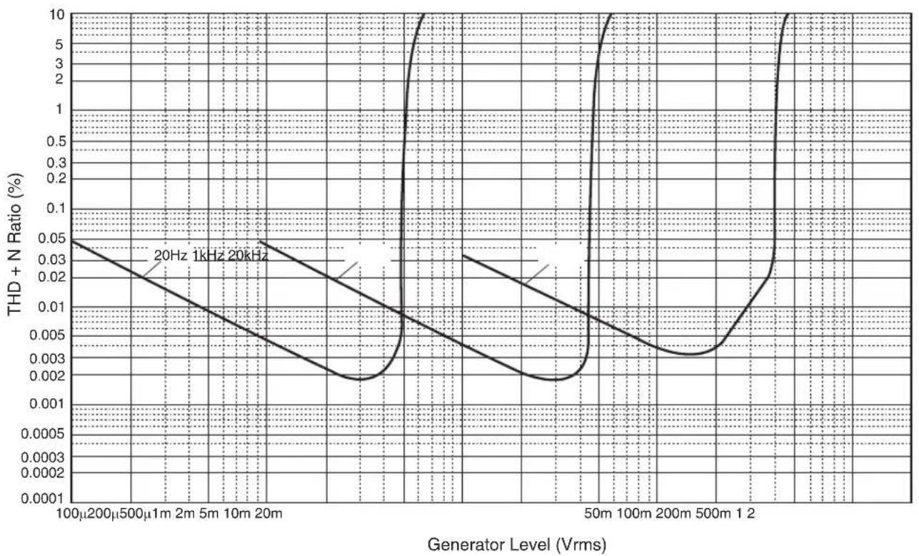
Total harmonic distortion plus noise
(JEITA, input 0.5 V, 20 Hz to 20 kHz)
2-channel driven
PHONO (MC) LINE 2 OUT, 1.2 Vrms .0.02%
PHONO (MM) LINE 2 OUT, 1.2 Vrms .005%
CD (or similar)/BAL 1/BAL 2
SPEAKERS OUT, 50 W/8Ω. 0.035%
Signal-to-noise ratio (JEITA, IHF-A network)
PHONO (MC) 90 dB
PHONO (MM) 96 dB
CD (or similar) 110 dB
BAL 1/BAL 2 114 dB
Residual noise (IHF-A network)
33 Vrms
Channel separation (JEITA, 1 kHz/10 kHz)
PHONO (MC). 66/77 dB or higher
PHONO (MM) 90/77 dB or higher
CD (or similar)/BAL 1/BAL 2 .74/54 dB or higher
Tone control characteristics
BASS
Boost/cut 50 Hz/±9 dB
Turnover frequency. 350 Hz
TREBLE
Boost/cut 20 kHz/±9 dB
Turnover frequency. 3.5 kHz
Meter accuracy
Class 2.5
Power supply
[Models for U.S.A. and Canada] ... AC 120 V, 60 Hz
[Model for China] AC 220 V, 50 Hz
[Model for Korea]AC 220 V,60 Hz
[Model for Australia]AC 240 V,50 Hz
[Models for U.K. and Europe]AC 230 V,50 Hz
[Model for Asia] AC 220-240 V, 50 Hz/60 Hz
[Model for Taiwan].AC 110 V,60 Hz
Power consumption
350W
Standby power consumption
OFF mode 0.1 W
Standby mode 0.2 W
Maximum power consumption (1 kHz, 4Ω 10% THD)
[Model for Taiwan] 700 W
Dimensions (W× H× D)
435× 180× 464mm
Weight
24.7 kg
- The contents of this manual apply to the latest specifications as of the publishing date. To obtain the latest manual, access the Yamaha website and download the manual file.
Appendix
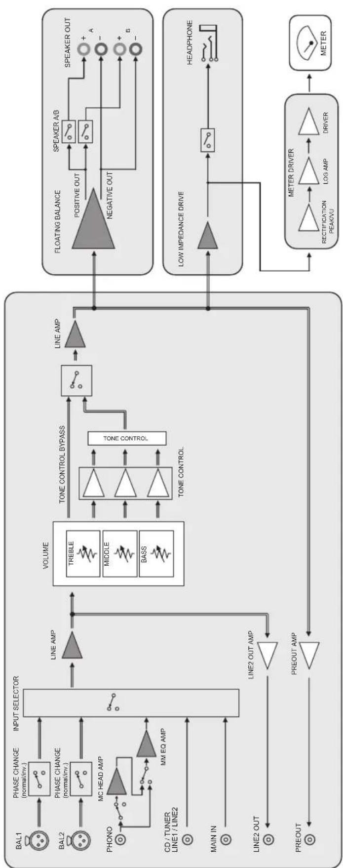
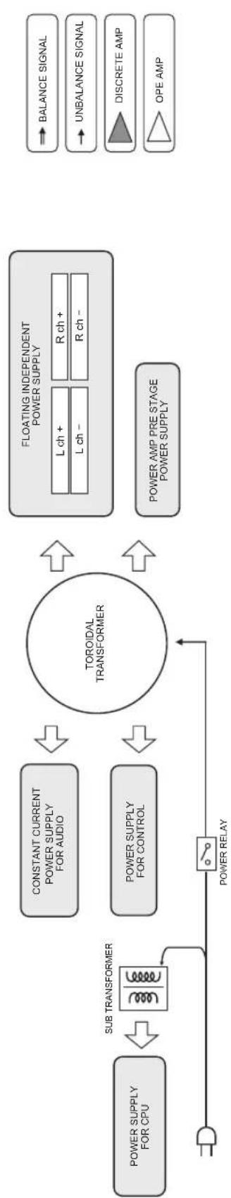
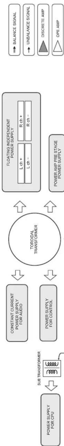
Block diagram
Acoustic characteristics

■Tone control characteristics
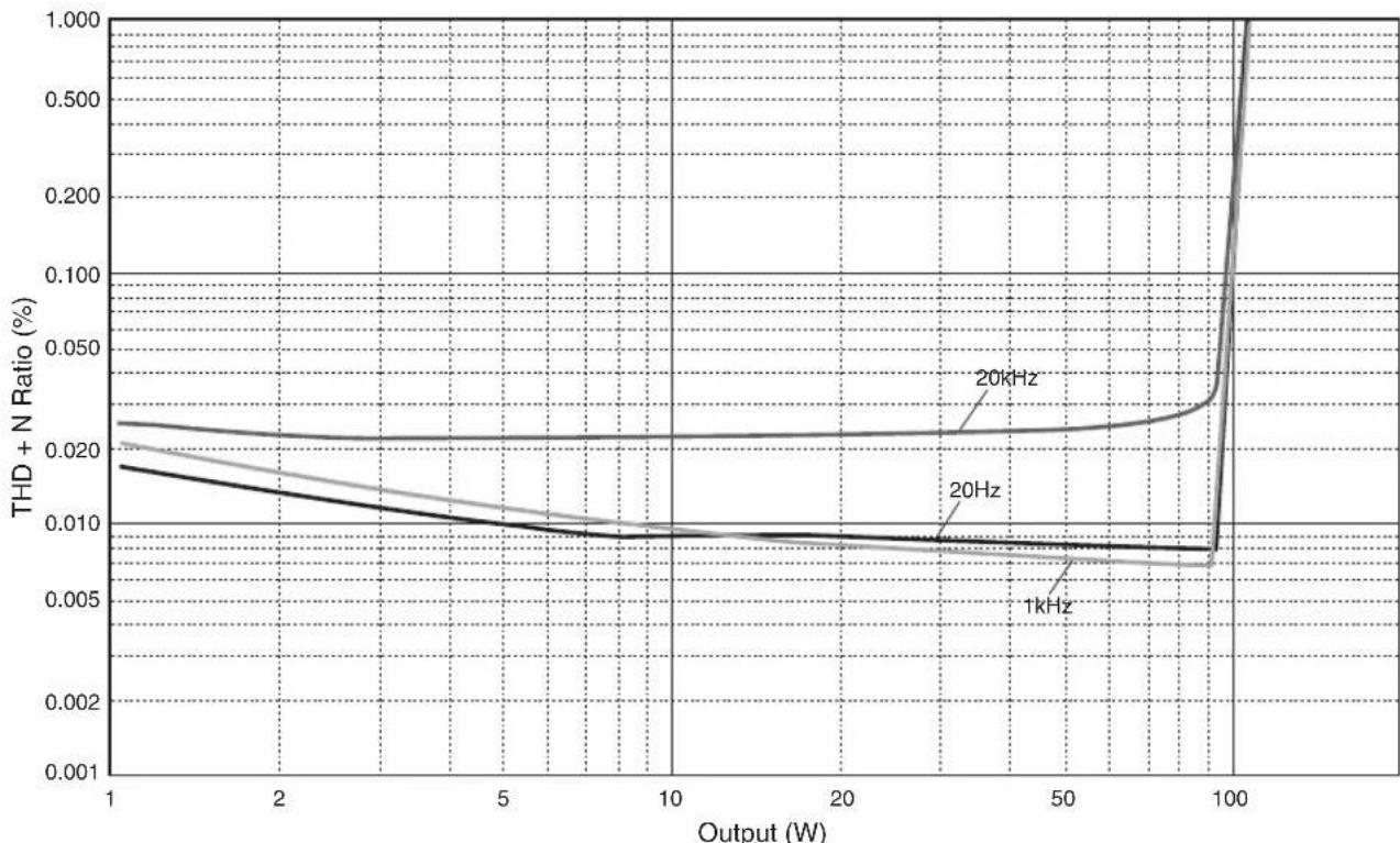
Total harmonic distortion
Appendix
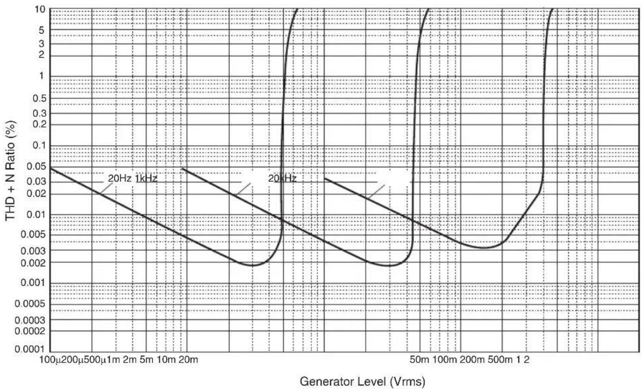
Total harmonic distortion (PHONO)
Troubleshooting
Refer to the table below if this unit does not function properly. If the instructions below do not help, or if the problem you are experiencing is not listed below, turn off the unit, disconnect the power plug, and contact the nearest authorized Yamaha dealer or service center.
| Problem Cause Remedy | See page | ||
| Power does not turn on. | The power cable is not connected to the AC IN connector on the rear panel or is not plugged into an AC outlet. | Connect the power cable firmly. 22 | |
| The unit has been exposed to a strong external electric shock (such as lightning or strong static electricity). | Turn off the unit, disconnect the power plug from the AC outlet, wait for about 30 seconds, and then plug the unit in again. | — | |
| The (Power) indicator on the front panel flashes. | The protection circuitry has been activated because of a short circuit, etc. | Make sure that the speaker wires are not touching each other or shorting out against the rear panel of the unit, and then turn on the power to the unit. | 18 |
| There is a problem with the internal circuitries of this unit. | Disconnect the power plug from the AC outlet and contact the nearest authorized Yamaha dealer or service. | — | |
| When the unit is powered on, the INPUT indicator flashes and the volume level decreases. | The protection circuitry has been activated because of a short circuit, etc. | Make sure that the speaker wires are not touching each other or shorting out against the rear panel of the unit, and then turn on the power to the unit. | 18 |
| No sound is heard. | Incorrect input or output cable connections. | Connect the cables properly. If the problem persists, the cables might be defective. | 16 |
| No appropriate input source has been selected. | Select an appropriate input source using the INPUT selector on the front panel (or one of the input selector keys on the remote control). | 8, 12 | |
| The SPEAKERS selector is set to OFF. | Set the SPEAKERS selector to the appropriate position. | 7 | |
| The speaker cables are not connected properly. | Make sure that the speaker cables are connected properly. | 18 | |
| The sound is suddenly muted. | The protection circuitry has been activated because of a short circuit, etc. | Make sure that the speaker wires are not touching each other or shorting out against the rear panel of the unit, and then turn on the power to the unit. | 18 |
| The volume level cannot be adjusted. | MAIN DIRECT is selected as the input source. | Adjust the volume level on the connected component. Alternatively, connect the external component to a pair of the input jacks other than the MAIN IN jacks, and then select the corresponding input source. | 8 |
| Only one channel speaker can be heard. | The playback component or speakers are not connected properly. | Make sure that they are connected properly. If the problem persists, the cables might be defective. | 16 |
| The volume level balance between the left and right speakers is not adjusted properly. | Adjust the volume level balance between the left and right speakers properly using the BALANCE control. | 8 | |
| Problem Cause Remedy | See page | ||
| There is a lack of bass and no ambience. | The + and - wires are connected in reverse at the amplifier or the speakers. | Connect the speaker wires to the correct + and - phase. | 18 |
| A "humming" noise is heard. | Incorrect input or output cable connections. | Connect the cables properly. If the problem persists, the cables might be defective. | 16 |
| The turntable is not grounded to the GND terminal. | Connect the turntable to the GND terminal of this unit. | 16 | |
| Playback audio from the component connected to the BAL 1 or BAL 2 input jacks sounds distorted. | The level of the signal at the balanced input jacks is exceeding the allowable input level. | If the level of the signal at the XLR-type balanced output jacks on the connected playback component is doubled compared to the RCA unbalanced jacks, set the ATTENUATOR selector located below the input jacks to ATT. (-6 dB). | 20 |
| Bass lacks depth when BAL 1 or BAL 2 is selected. | The polarity is incorrect. | Select the correct polarity using the PHASE selector. | 20 |
| Playback audio is distorted while you listen to a connected CD player or tape deck through headphones (that are connected to a CD player or tape deck). | The power to the unit is turned off. Turn on the power to the unit. 6 | ||
| The volume level of the vinyl record is too low. | The PHONO switch on the front panel is set incorrectly. | Set the PHONO switch to the MM or MC position according to the type of magnetic cartridge of the turntable. | 9 |
| The remote control does not work or function properly. | The remote control has been used out of the operating range. | The remote control must be used within a maximum distance of 6 m and no more than 30 degrees off-axis from the remote control sensor on the front panel. | 14 |
| Direct sunlight or lighting (from an inverter type of fluorescent lamp, strobe light, etc.) is hitting the remote control sensor on the front panel. | Change the orientation of the lighting or reposition the unit. | - | |
| The batteries are weak. Replace all batteries. 14 | |||
Maintenance
Mirror-finish side panels
We recommend that you use a cleaning cloth such as those made for pianos.
Other surfaces
Do not use chemical agents, such as benzene or thinner for cleaning. Otherwise, the surfaces might be damaged. Wipe the surfaces using a soft dry cloth.
13 Prises REMOTE IN/OUT
Accentuation/attenuation 50 Hz / ±9 dB
Accentuation/attenuation 20 kHz / ±9 dB
Consummation maximum (1 kHz, 4Ω, DHT 10%)
(JEITA, 1 kHz, 10% THD)
[Asien-Modell]
Bi-wired anslutning 103
⑬REMOTE IN/OUT-uttag
Anslut externakomponenter som stoder den fjarrstyrdafunktionen. ( sidan 105)
14TRIGGER IN-uttag
Anslut externakomponenter som stoder triggerfungkctionen. ( sidan 104)
15ACIN-uttag
Anslut den medfoljande strömsladden hit. ( sidan 106)
(JEITA, 1 kHz, 10% THD)
[Modell for Asien]
MAIN IN 1 Vrms/47 kΩ
BAL 1/BAL 2 200 mVrms / 100 kΩ
Maximal signalspanning vid ingang (1 kHz, 0,5% THD)
PHONO (MC). 2,0 mVrms
PHONO (MM) 50 mVrms
CD (eller liknande) 2,80 Vrms
BAL 1/BAL 2
BYPASS. 2,80 Vrms
ATT. (-6 dB). 5,60 Vrms
[Modell for Taiwan] 700 W
Matten (B× H× D)
435× 180× 464mm
Vikt
24,7 kg
13Prese REMOTE IN/OUT
Collegamento bi-wire
Rumore residuo (rete IHF-A)
33 Vrms
Consumo energetico in standby
④ Selector SPEAKERS
MAIN IN 1 Vrms/47 kΩ
BAL 1/BAL 2. 200mVrms / 100k
PHONO (MC). 2,0 mVrms
PHONO (MM) 50 mVrms
CD (o similar) 2,80 Vrms
BAL 1/BAL 2
BYPASS 2,80 Vrms
ATT. (-6 dB). 5,60 Vrms
(JEITA, 1 kHz, 10% THD)
[Model voor Azie]
MAIN IN 1 Vrms/47 kΩ
BAL 1/BAL 2 . 200mVrms / 100k
Maximum ingangs/signaalvoltage (1 kHz, 0,5% THD)
PHONO (MC). 2,0 mVrms
PHONO (MM) 50 mVrms
PNEyPEXDEHNE 063NaeT Mepb IpeIOCTOPoKHOCTN, KOToBie cJIeJeYeT co6HOaTb, TTO6bI
H36eKaTb Pncka CmeptN HJIN cepBe3HOJ TpaBMbl.

BHIMAHNE 603NaHaet MepbI IpeIOCTOpOKHOCTH, KOtOpbIe CJIeJyET co6JIHOaTb, YTO6bI H36eKaTaB
pHcKa TpaBmbl.
- YBEOMJHEHNE 603Haayet Meby IpeIOCTOpOxHocTH, KOToPbIe cJIeIyET COJIIOaTb, YTObI H36eKaTb HeNCIIpaBHOCTH ININ IOBpeKJeHnI IPOJyKta.
PpIMeuaHne
0603HaaeTIOIOJIHHTeJbHyIHO HHOpMaIHIO O IpoJyKTe.
PoctabJЯeMbIe akceccyapbl
Y6cintecb,HTO cIcyIOUHne akccceyapbBXoJrB KOMUIICKT IOCTABKN.
-Пульт ДY
- BaatarpeiKn (AAA, R03, UM-4) (× 2)
CnIOBoI Ka6eJIb*
PykoBOCTBOIOJIb3OBaTcIg(JaHHaKHHra)
-Броллора пio 6e3oIacHocTH
*B KOMIIJEKT IIOCTaBKN MOrYT 6bITb BKJIIOueHb HeCKOJIbKO cJIIObIX KaIeJIe B 3aBHcHMOcTH OT peRHOHa pacIPOcTpAHeHH.
HcIIb3yIte Ka6eJIb, KOtOpbI COOTBeTcTByeT po3eTke IpeMeHHOrTo TOka.
Copepkne
ΦyHKcMn 199
Hhopmaunna Ira 03HaKOMNeHnnepe
nCnoJIb3OBAHHeM npOdyKta. 200
O daHHOM pykoBODCTBe. 200
IocTbAJIeMbIe akceccyapbl 200
Ha3BaHnA KOMNoHErOB uNx xfYHKuun.....201
Pepednnaheb 202
3aHnaHb 206
PnybT dy. 208
UcTaHOBka 6aTapeeK B nyIb T y 210
UnpaBHeHne c nOmoosbIO npIbTa Dy. 210
IopknloueHna 211
Cxema nookloueHna 212
IopKnloueHne KOHOK 214
IcnoB3OBAHnE Ka6eNe KOnHOK. 214
IcnoB3OBaHnE Ka6eNe C 6aHaHOBBIM WTekepOM..215
IcnoJIb3OBAHnE Ka6eJe C BUNKoo6pa3HbIM
HaKoHeuHkOM 215
YeTbipexnpoBoDnOe noKnIoueHne 215
CmmMeTpnuHoe coeDHeHne. 216
Tprrrephoe coeunHeHne 216
ДиТанцИоHhoe coeINHeHne 217
UnpaBHeHne annapaTOM 3 pyroKOMHaTbI..217
ДиctaHcHIOHHOe coeINHeHne MeKdY
KOMNOHENTamYamaha. 217
Iopknoyehne cnloBoro ka6ena 218
PpuloxKeHne. 219
Texnueckne xapaKtepnctnkn. 220
BloK-cxema 222
Akyctnueckne xapaKtepncn. 223
XapakTepcntKpupeynipOBkn Te6pa....223
Ko3ΦHnueHT HeHHHeHbIX NcKaXeHn. 223
Ko3ΦΦnUeHT HeJIHeHbIX NcKaXeHn
(PHONO) 224
Bo3MOxHbIe HEnCnPabHBocn n CnOc6blnx
yctpaHenn 225
Texnueckoe 6cnykBaHne 226
Ha3BaHnY KOMNoHErTOB IN IX ΦyHKuIN
B IaHHOM pa3JeIe IIpeIcTaBJIeHbI Ha3BaHHN I yHKIIIN pa3JIHbIX KOMIOHEHTOB Ha IpeIeHn I 3aJHei IaHeJIH n IIyJIbTe IY.
Ha3BaHЯ KOMnoHeTOb Inx ΦyHKcIa
PepednnaHeIb
YAMAHA
①Пepeknquatelb/mHdNKaTOp (Ntahne)
Ha3BaHnY KOMNoHcTOb INxΦyHKcN
3aHЯ paHeIb
① BxOaHbIe rHe3daTUNER
②TepmHaN GND (3a3eMJIeHne)
IpnIOKJIIOHcHHN pOONrPBbATEJ K DaHHOMy aIIapay 3a3eMHTte erO uepe3 TepMHHaI GND. 3To MOKeT cHn3HTb IyM.

BHUMAHNE
He ocna6nIte roJOBky TepmHana GND cnNikom cnIbHO. B npOTNBOM cnyae OHa MOKeT OTcoeHNITbcra n pe6eHOK MOKeT cnyaaiHo ee npOrIOTNTb.
PnmeaHne
3To He YBJIaETc8 6eONaChbIM 3a3EmnHeHnEM.
③ BxoAnbIe rHe3da PHONO
④BxOaHbIe rHe3da CD
⑤ Bxodhbirehe3daBAL1/BAL2 (cmmMeTpHbIe)
PpmeaHne
UcTaHOBInTe celenkTop ATTENUATOR n celenkTop PHASE B NOIOKeHne, COOTBeTCTByIOoee KOMNoHeHTaM BOCIpOn3BeDeHn, KOToPbIe NODKJIIOueHbI K aIInapaTy. ( cTp.216)
⑥ Nepekekuateleb AUTO POWER STANDBY
ON: AnnapaT nepexoINT B pexm OxHaHn aBTOMATNHCCKH, ccln HHTaHHe BKIOUcHo, HO HKKHe OIepaHH He BbIIIOJIHOITcB TceHHe BOCbMn YacOB (fuykna Auto Power Standby).
OFF: Annapat Hc npexoHT B pekm OkndaHn aBTOMaTHCCKH.
⑦ BxoDhbIe rHe3da LINE1
⑧ΓHe3da LINE 2
IIOKJIIOHHTe K HMM BHEIHINc KOMIOHHeHTbI, KOToPbIE HMCOT aHaJIOROBbc IHC3da BBOJa/BbIBOJa ayIOCHIHVA.

9The3a PRE OUT
PpumeyaHne
AynocnHaBb, BbIOMbIe uepe3 rHe3a PRE OUT, aHAnoruHbCnHaJAm KaHaNoB, KOtOpbie BblBOJrTa uepe3 TepmHaJIb SPEAKERS L/R CH.
Cnelyuioue 3naeHn npaMeTPOB 000kTNBbI yauinocnHaIOB, BbIBoINMbIX uepe3rhe3da PRE OUT.
-BASS
-TREBLE
-BALANCE
VOLUME
10The3a MAIN IN
IIOJIIOHTe K HMM BHeIIHHe KOMIOHEHTb, KOToPbe HMCIOPTyIKHIO pCryJINpOBKN rPOMKoCTH, YTObI daHbI aHapAT MOKHO 6bIIO HcIOJIb3OaTbB KaueCTBe yCHJIHTeJI MOIIHOCTH.
YBEDOMJIENHE
EcnB Bb6paHO 3HaueHHe MAIN DIRECT B KaueCTBe nCTOuHNka BXoHOrO CnHnla dJa daHoro aannapata, ypoBeHb rPOMKocTn 6yJeT fNkCnpOBaH. B 3ToM cnyae, OTpeRynpyTe yPoBeHb rPOMKocTn C NOMOsbpeYJLTopa rPOMKocTn Ha BHeuHem ycuiNTe, NOKnIOUeHHOM KrHe3dAm MAIN IN.
① TepMNHaJIbI SPEAKERS L/R CH
12Tne3do SERVICE
IaHHoe rHe3IO HcnoJIb3yETcIJI TecTHPOBaHnI npOuykTa.
13THe3da REMOTE IN/OUT
IIOKJIIOHHTe B HMM BHeIIHHe KOMIOHEHTbI, KOITOpBIE IIOJIepKHBaiOT fYHKINIO DnCTaHIHOHHOyIpaJIeHNr. ( cTp.217)
14The3doTRIGGERIN
HIOKIOHTe B Hemy BHeHHne KOMHOHeTbI, KOtOpBte HIOJIepKHBaOT TpHTTePHyIO yHKIIIO. ( cTp.216)
15Tne3oACIN
ПОДКЛЮЧNTe K HEMY IIpHJIaRaembI cHIOBOI Ka6eJIb. (→cTp.218)
Ha3BaHЯ KOMnoHETOBи nx φункциn
NynbT dy
①NepedaTnK INHpaKpaChoro CmRHa
BbIOH HΦpaKpaCHbIX cHIIaIOB yIpaJIeHHB HApBaJIeHH anIapata. ( ctr.210)
②Khonka AMP
BKKIOUeHHe IIHTaHHHa aIIIapate HIN IIpeKJIIOueHHe BpeKM OxHuaHH. ( ctp.202)
③KhoNKn BbI6opa BxOaHoro CnHaHa
Bb6op hctouHnka BXoIHHO cHHaJa.
AyINOCHTHaIbI BbIbpaHHO HcTOHHKa BXOHNORCnHaJa 6yDyT BBIOHTbcra Hepe3 rHe3da LINE 2OUT.
BAL 1/BAL 2: Bb6op KOMIOHEnTA, IOKJIIOHeHHORO K BXoIHbIe THe3Ja BAL I INB BAL 2, B KaueCTBe HCTOuHnKa BXoIHOrO CnHaJia.
LINE 1/LINE 2: Bb6op KOMnoHeHa, NOJKNIOHeHHORO K rHe3dAM LINE 1 HIN LINE 2, B KaCCTBC HcTOHnKA BXoHnO CRHaJa.
PHONO: Bb6op IpoHrpBATEJI, IOKJIOueHHORO K BXoIHBIE THe3Ja PHONO, B KaueCTBe NcToUHnKa BXoIHoro CNHaJa.
MAIN DIRECT: Bb6op KOMIOHeHTa, IOKJIIOeHHORO K THe3JAM MAIN IN, B KaueCTBe HCTOUHnKa BXoHOrO cHHaJa.
CD:Bb6op CD-ⅡpoHrpBbATEJI,IOKJIIOHeHHORBXOHNBE THe3Ja CD,B KaueCTBe HcTOUHHaBXoHORO CHHaJIa.
TUNER: Bb6op TIOhepa, IOIKJHOeHHOrO K BXOHbIe rHe3Ja TUNER, B KaueCTBe HcToHHKa BXOHORO CHHaJIa.
PpmeaHne
- Ecnn 3haeHne MAIN DIRECT Bb6paHO B kaueCTBe NCTOUYnka BXoJHoro CnHa,aynocnHaJIb He 6ydyT BBIOaITbcra Ype3 rHe3da PRE OUT, LINE 2 OUT nn PHONES.
- EcnBb6paHO 3NaueHne LINE 2,aydnocnHaJIbI He 6ydyT BbOaNTbcqyepe3rHe3da LINE 2 OUT.
④KhoNkVOLUME+/-
PeryIINPOBka ypoBHa rpoMkoCTH. JaHHa HacTPOIIKa He BIIHReT Ha ypoBeHb BbIXoIHOrO cHrHaJIa Ype3 rHe3Ja LINE 2 OUT.
YBEDOMJIENHE
EcnBb6paHO 3NaueHne MAIN DIRECT B KaueCTBe
NcToUHnKa BXoHOrO CnHaJa Dn DaHHoro aInapata,
yPoBeHb rPoMKOCTn 6yDeT fNkCupOBaH. B 3Tom Cnyae,
OTpeRyIuPyTe yPoBeHb rPoMKOCTn C nOMOuBu
peYJLTopa rPoMKOCTn Ha BHeuHem ycuiNTe,
NoKJIoueHHOM KrHe3dAm MAIN IN.
⑤KhoNka MUTE
HaKMHTeHaHHyIO KHOIIKy IIN yMeHbIeHn
TeKyuIero yPOBHy rPOMKOCTN pIN6JIIN3HTeJIbHO Ha 20
16. HaKMHTe KHOIIky eIe pa3 IIN BOCCTaHOBJIeHn
IpeIbIyIeO rPOBHy rPOMKOCTN.
⑥ Khonkn ynpaBneHn TIOhePOM
YipapBicHe cyHKnMn IIOKHOCHHOro TIOHepa
Yamaha. PioP6Hec cm. B pyKOBoCTbc
IIOJB3OBaTeJI TIOHepa.
⑦KhoNKn ynpaBneHna CD-npOuRpbIbAteJeM
YnpaBJeHHe yHKIIHMN IIOIKIHOeHHORo CD- npOHrpBbATEJyamaHa.IpOp6Hee cm. B pyKOBOCTBe IIOJIb3OBaTeJc CD-IPOHrpBbATEJia.

KhoIIKa OPEN/CLOSE: OTKpbIte He HIN 3aKpbIte He JOTka IIncKa IIOIKJIHOeHHOro CD- IIPOHrpIBaTeJI.
KhoKa CD:BkHoyeHHe HHTaHHHa IIOJKJIOueHHOM CD-HPoHrpbBaTeJIe HJIn eI OpeKJIOueHHe BpeKM OxHaHH.
(Bocipon3BeHHe):HaayIO BOCIPOHN3BeEHHa CD-ppoHpblBaTeJIe.
(1ay3a):Pay3a npn BocnpoH3BcEChHH Ha CDpOHHpaTeJIe.
HaKMHTe HJH I JIy BO306HOBJCHHH BOCpOHN3BeJeHH.
(ocTAnOBKa):OcTaHOBka BOCIIPOH3BCIeHHa CD-IPoHrpBaTeJIe.
( nponuc): IepexoHa cneIyOuIy OpoKky HIN BO3BpaT K HaayIy TckUcH OpoKKn.
KhoIIKa SOURCE: Bb6op HcToHHka IJIa BocIpOn3BcEeHn c IIOMOIbIO CD- IIpoIHpBbAteJI. IIpi KaJIOm HaKaTHN 3TOI KHOIIKN H3MeHReTcHcTOHHK IIa BocIpOn3BcEeHn.
KhoIIKA LAYER: IepckIIOueHHe cIO8 BocIIpoH3BcIeHHra H6pHIOHO dNcKa Super Audio CD mKJy "Super audio CD" n "CD".
Прмочинe
HekotopbIe TIOhepyi n CD-mpoUrpbIbATEyama MoryT He nopeKnBaTb KHOKN ynpaBHeNn TIOhepom nn CD- npOurPbIBaTeJEM.
Ha3BaHЯ KOMnoHETOBи nx φункциn
YcTaHOBka 6aTapeek B nynbT dY
1Chnmte Kpbikky otdeleHna 6aTaapeek.
2BCTaBbTe DBe 6aTapeKn (AAA, R03, UM-4) B COOTBeTcTBn C O6o3HaueHnA Mn NOJARHOCTn (+ n-) Ha BHyTppeHne CTOpOHe OTdeneHnI dIg 6aTapeek.
Unpablenne c nomoubIO npbTa dy
C HOMO BIO IyIbTa DY MOxH OcyuieCTBJIbTb yIpaBJIeHHe B IIpeJIax Yka3aHHOro HIXke IHaIIa3OHa, HAIIpaBHB eRo Ha ceHCop IInCTaHHOHOrO yIpaBJIeHnHa IIpeJHe NpHeN AnIapara.
3yctaHOBNTe Ha MeCTO KpbIshky OTdJIeHnA Ira 6aTaapeek.

Подключения
B JaaHHOM pa3JeJe oINcsbIbAeTcra IpoIeIpya IIOKJIIOueHna aIIIapata K KOJIOHKam H NCTOCHNKam ayINOCnIHajla.
Cxema nodkloueHna

BHIMAHVE
063aTeNbHO 3aBepuHrCe NpOKnIouHeHn, IpexJe Yem IIOCoEINHHTcNIOBOH Ka6eBnK pO3eTKe IpeMeHOro ToKa. ( cTp.218)
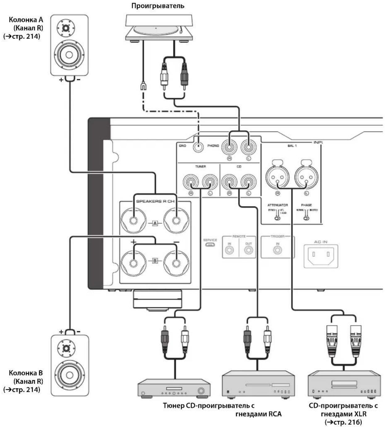
YBEOMJIEHNE
ECNI KOMNOHENT NOKIIUeH K rHe3dAM MAIN IN, ypoBeH rPOMKOCTn annapata 6ydet
fHKcnpoBaH. IOTOMY He cIeNyET NOKIOuATb CD-npOurpblateBn nn dpyrne
KOMHOENTbl, KOtOpBle He nmeKOT fHyKnU pErynlnpOBKn rPOMKOCTn, K rHe3dAM MAIN
IN. B npOTNBOM Cnyae BO3MOxH BOcIPOn3BedeHne rPOMKOrO 3Byka, YTO MOXeT
npUBeCTN K HcNpABHOCr AnnapaTn NIOBpeKJeHIO KOLOHOK.
PpMeyaHne
Tak Kac ycunntelb MoHocn OTHOCNTc K PnaBaIOuemy CMMMeTPNCHOMY TINy, HeBO3MOXHO BbINOHNb CNeDyUOune NOKNIUOHeHNA.
-ПОДКИЧЕНМЕЖДУДБΥМЯТЕРМИHAлAMN"+"(ПИДБΥМ"-")Левого И павoro KaHana(Pnc.1).
-Подклочене кадог� Термнана "-" NeBOrO n npaBOrO KaHana annapaTaknpotNBONIOJXHbIM KaHaNAM KOLOHOK (nonepueHoe coeINHeHne, Pnc.2).
-Подклочен TePmHahOB"-"IeBOrO n npaBOrKaHaJa K MetaJIuYeCKo YacTn Ha 3aHne NaHEn annapata (iIN IN ClyuaHoe cOpNKOCHOBeHne).
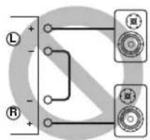
Pnc.1
Pnc.2
He noKluaye akTnBHy ca6Byep K TepMHaJAM SPEAKERS L/R CH. PoiKluoyte ca6Byep K rHe3aM PRE OUT Ha annapate.
Подключени Колонok
IcnoJb3ObaHne Ka6eJeN KOJHOK
1 ydaIte npu6n3ntbHo 10 MM n3OJauNHO CNoHa KOHuaX KaKdoRo Ka6eJa KOJOnHKn I NIOTHo CKpyTHe OTKpbITbIe npoBaKa6eJa IJI npedOTBpaueHn KOpOTKO 3aMbikHn.
2 Otkpytnte roIOBky kaxdoro TepMNHaJa KOLOHKn, a 3aTeM BCTaBbTe OOrJeHHbI npOBd B 60KOBoe OTBepcTne Ha TepMNHaJe.
Bce noKluoyehna DOnJXhbl 6bIb npabInhblIMn: L (neBbl) K L, R (npabbl) K R, "+" K " " " " " " .HfOpmauio o npoueype noKnluoyehna CM. BpykoOaCTBe Nolb3oBaTeTg KOHOHK.
IcnoB3OBAHne Ka6eNe c 6aHaHOBbIM uTekepom
(MoJIeJIH IIJI CIIIA, KaHaIbI, ABCTpaiHH, KITraN TaIbAH)
Chauana 3akpyTnte roIobky Ha TepMNHaJe SPEAKERS n 3aTeM BCTaBbTe 6aHaHOBBi uTeKepe B HakoHeuHK roIobKn.
IcnoIb3OBAHne Ka6eNei c BnIKoo6pa3HbIM HaKOHeuHNKOM
10TKpyTNTe rOIOBky n 3aTeM BCTaBbTe BnIKOO6pa3HbI HaKOHeuHk MeKdy KOJIbueBOJ YacTbIO N OCHOBaHmE TepMNHaJa.
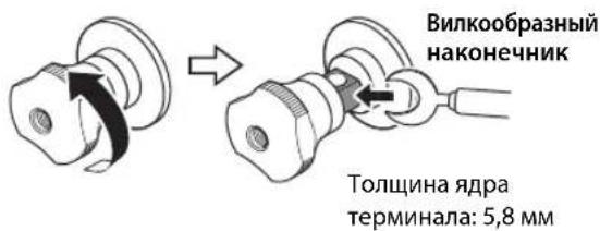
23akpytute roNoBky.
YeTbIpexnpoBODhoe NOdKJIouyehne
YcTbipexIPOBOHOIOEIOIKIOOHIEIO3BOJIaETOTIDJITB HIN3KHe YAcTOTbIOTINHAna3OHa cpeIHnX N BbICOKHX YacTOT.KoIOHNK, KOTOpBIE IOIDePJKHbAOT YcTbipexIPOBOHOIOEIOIKIOOHcHc, HMeOT DBe IapbI TepMHNAIOB (BCero YoCTbipe TepMHNAJIa).OTN DBe IapbI TepMHNAIOB IO3BOJIaOT pa3DEJHTB KOIOHK Ha DBe He3aBNCMBie rpyII.ДЯ TaKOrTO TIIIA IOIKIOHcHn HEO6XoIMMO IIpHCOeIHINTb IIpHBOblcpeIHNX H BbICOKHX YAcTOT K OIOH Iape TepMHNAIOB,a IIpHBOblI HIN3KHX YAcTOT K JpyrToI Nape TepMHNAIOB.
1ydaJIte 3aMbIkaUoUne nepeMbIcKu nn MOCTIKN Ha KOJOhKaX.
2NoKIOUHTe annapaT K KOLOHkAm, KaK noka3aHO ha pucyHke HIXKe.
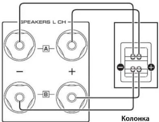
Ppimep nooknueHnaeBoro KaHana
3aHnaHb annapata
3yctahOBtce ceneKTop SPEAKERS Ha nepeHne naneB noLoXeHne A+B BI-WIRING.
Покlioqueeя
CmmMeTpnuHoe coeHHHeHne
MOKHOIOIKIOHTb CCTBOH HIN CD-HPONHPBATEJIb, KOtOpbI HMeET CHMMETPHHBE BIXOHNbIE THe3Ja THIIa XLR, K BXoIHbIe THe3Ja BAL 1 HIN BAL 2 Ha annapate. Jn daHHoro COcHHHnHnHn HCIOJIb3yIte CHMMETPHHbc Ka6JIu THIIa XLR.
CeJekrop ATTENUATOR: IIO3BOJIaCT yCTaHaBJIHBaTb IOIyCTHMbI yPOBeH bXoIHHO rHrHaJa IIIN CHMMCTPNHbIX BXoIHbIX rHc3d. Bb6epntc 3HaueChnC ATT. (-6 b) ecIIH ayDIOCHrHaJI, BBIOHMbI H3 IIOKJIHOHHOrO KOMIOHeHTa, 3ByHT NCKaKeHHO.
CeJekTop PHASE: IIO3BOJnAET yCTaHaBJIHBaTb IIOJOCKHnC (IOJIApHOCTb) KOHTAKTa HOT (KOHTAKTa #2: HOT HIN KOHTa#3: HOT) Ha cHMMeTpHuHbIX BXOHNbIX rHe3dax.
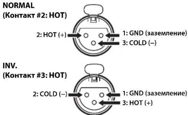
O6paTHTcB K pyKOBOCTBy IIO IOIKJIOHCHHOMY KOMIOHOHTy, YTO6bI y3HaTb IIOJOKeHne KOHTaKTA HOT B CHMMETPNHbIX BIXOXHbIX THe3JaX KOMIOHEHTa.
PpimeyaHne
- Bb6epnte 3aueHne NORMAL (KoHTaKT #2 ABnEerKa KOHTaKTOM HOT)ДЯпоирьВаTeЯ YamaHa.
He nCnoB3yIte CmmMeTpnuHbIe HecmMmTpnuHbIe COeINHeHnI DnOdHO KOMNoHEHa ODHOBpeMeHHo.3To MoKeT cOpMnpoBaT KoHTyp 3a3EmHeH, KOtOpbIc CO3daeCTaTnueCKne NOMExuWym.
-Пи NOДКЛIOUeHIN Ka6eIЯOB3aTeJIbHO COBMeCTnTE KOHTaKbI pa3bemaC OTBepCTnMn rHe3da,a 3aTeM BCTaBbTe WTeKePbI pa3bem XLR Br He3do Do ueNka. YTo6bl OTcoEINHnTb Ka6eIb, HaxmITE n ydepXnBaIte pbIaJOK Ha BXoHNbIe rHe3de BAL 1nnn BAL 2 n BbITauNTe wTeKePbI pa3bem XLR n3 rHe3da.
-ДясnmmetpnuHOro coeHHeHnBb6epnte BAL 1 nNn BAL 2В kaueCTBe NcToUHnKa BXoHOrO cnHaJa.
Tprrrephoe coeHenne
MoKHO IOIKJIOUHTb AV-pcchBepYamaHa HIN IpyrO
KOMIOHcHIT, KOtOpbI IOIDecPKHBacT PnIHcrepHyIO
fYHKIIIO. MoKHO ynpaBIArTB daHHbIM aAnnapaTOM
CHHXPOHHo CIOIKJIIOUeHHbIM KOMIOHeHTOM.
3aHnnaHn b annapata
AV-pecnBep Yamaha nIn npyroKOMNoHEHT, KOToPbI uMeET rHe3daTRIGGER OUT n rHe3da PRE OUT
IIpn BKIOCHHHIITAHHIIIOIKIOOHHO KOMIOHHTA IITAHHe aIINapata TaKke BkIOHoeTc. OIOHBpeMeHHO c 3THM B KaeeCTBe HCTOUYHb KxOHO rHHaJa Ha aIINapat yctHaABJIBaETc 3NaueHHe MAIN DIRECT. EcII 3HaChHc MAIN DIRECT Bbl6paHb KauCtBc HCTOHHKa BXOHO rCHHaJa dJaAIHO rAIHpapaTa Ha MOMeHT, KOJa BbIKIOaCTc IIITAHHe IOIKIOOHCHO KOMIOHEHTa, DaHHb IANapat NepeiDet B peKM OKHaJAHN.
PpmeaHne
Korda nepekIouateIb nItaHna Ha anpapate yctaHOBnE H noLoXeHne OFF, nItaHne annpapa He 6ydt BKIOUATbcra.
Дистанционhoe coeHHeHne
Unpablenhe annapaTom n3 pyroKOMHaTbl
IpiHIOIKJIOeHHN HMeOIIIEcR B IpoJaKe HnΦpaKpachoro IIpneMHNKa H IpePaTCHKa K THe3JaM REMOTE IN/OUT Ha aHapate MOxHO yIpaBJIaTB aHapatOM H/HIN BHEIHINM KOMIOHcHTOM HdpyroH KOMHaTb c IIMOIIbIO IIpHlaeraMOr IOyIbTa IV.
NytB DBy BHeuHn KOMNOHEt
(CD-npounrpbIbATEnbT.Д.)
ДиctaHcHIOHHOe coeMHHeHMe MeKdY KOMnoHeHTamYama
Ipn HauHnHpyTOro KOMIOHeHTaYamaH, KOtOpbI IIOJIePKeHBaCTyHKIIHO INCTaHIIOHHORO COeIHHeHHA, HET HeO6XODIMOCTH B HHPaKpaPacHom IpePaTHeKc. IIOJIIOHHTe HfPakpacHbI IIpHcMHNK K THe3dAm REMOTE IN/OUT Ha aIIapare, KaK IOKa3aHO HnKe. MoKHO HAcTPOHTb IO TpEx KOMIOHeHTOB YamaHa (BkIOUaHJaHHbI aIIIapat) Ha INCTaHIIOHHoe coeINHEHe.
IyblT Dy KomnoHENTYamaha
(Do Tpx KOMNoHEtOB, BKNIOyA daHHbI aannapaT)
Покlioария
BbIXoHaMoUHocTbNoCTaHdApTyIEC
(1 kΓι, 0,07% KΗΝ)
[Moŋeɪb Iŋ CoeɪnHeHOrO KoponeBcTba n cTpaH Ebpɒbl]
8OM. 105Br+105Br
MaKcImaJIbHaN 3ΦΦeKTnBHaB BbIXoHaN MoUHOCTb
(JEITA, 1 kFt, 10% KHN)
[MoJIbIaA3n]
8OM. 110BT+110BT
4OM. 190BT+190BT
[Дугnev модаи]
8OM. 130B+130BT
4OM. 210B+210BT
Dnana3OH qACTOT NOLHO MOHOCHT
(0,1% KHN, 50 Bt)
2-kaHaJIbHbI
8OM. 10TnIO50KII
BxOHaH aYbCTBnTbHOcTb/BxOHaoe
conpoTMBJIeHne (1KΓU, 100BT/8OM)
PHONO (MC)
150MKB,cpeHHeKBaIpaTnHoe3HaueHHe/50OM
PHONO (MM)
3,5MB,cpeHneKbIpaTHuHoe 3HaueHHe /47 KOM
CD (HJn aHaJIIOrTHbI)
200MBcpeHnEKBaIpaTHuHoe3HaueHHe/47KOM
MAIN IN
1B,cpedKBAipatHnOe3HaueHHc/47KOM
BAL 1/BAL 2
200MB,cpedKBApaTnHoe3NaueHne/100KOM
MaKcMaJIbHoe HanpJxKeHne BXoDHoro CnHaHa
(1 kΓu, 0,5% KHN)
PHONO (MC)
2.0MB,cpeHneKBaIpaTHHoe3haueHHe
PHONO (MM)
50MB,cpEHeKBaIpaTHHoe3HaueHne
CD (nJn aHaJIOnTHbI)
2,80B,cpedekbaiparHnue3naeHHc
BAL 1/BAL 2
BYPASS.....2,80 B, cpeIHeKBAJaPaTnHoe 3NaueHne
ATT. (-6日) .5,60B,cpeIHeKBAJaPaTHHoe3HaueHne
HomHaJIbHoe BbIXOdHoe HApJxKeHne/BbIXoDHe
conpoTnBneHne
LINE 2 OUT
200 MB, cpeHneKBaIpaTHHoe 3HaueHHe / 1,5 KOM
PRE OUT
1B,cpedHeKBaIpaTHHoe3HaueHHe/1,5KOM
HomHaJIbHaB BbIXoHHa MoIooCTb pa3bema IJIa
HayshnkoB(1KfU,32OM,0,2% KHNI)
50MBT+50MBT
YacToTHaXapaKTePncTnKa
or 5Γu do 100 kΓu. +0/-3 dB
or 20 _ do 20 _ . +0/-0,3dB
OTKNOHeHnO T KBaIaIepaRIAA
PHONO (MM/MC) ± 0,5 πB
Ko3ΦnueHT HeHHeHbIX NCKaKeHm C yyeTOM Wyma (JEITA, BxOJ 0,5B, oT 20 Tdo 20 KfU) 2-KaHaJIbHbI
PHONO (MC) LINE 2 OUT,1,2 B, cpeIHeKBAipaTHHoe 3HaueHne. .0,02%
PHONO (MM) LINE 2 OUT, 1,2 B, cpeIHeKBAIIpaTHHoe 3HaueHHe. .0,005%
CD (HIN aHaJIOTnHbI)/BAL 1/BAL 2→ SPEAKERS OUT,50BT/8OM .035%
[MoJIeJIH IJIa CIIIA H KaHaIbI]
120B IepemHHO ToKa,60
[ModJIbIJIaKHTa] 220B IepeMeHHOro ToKa,50 T
[MoJIbIJIaKOpH] 220B IepemEHHO ToKa,60I
[MoIeJIbIIIAABCTpaJIHH] 240B IIepemEHHO ToKa,50 T
[MoJIeJIH JIJI CoEHHHeHHOro KopJIeBCTBa H cTpaH EbpOJIbI] 230 B IIepMeHHOro ToKa, 50 T
[MoJIbIaA3HH] 220-240BIIepeMeHHoTOka,50T/60T
[MoIeJIbIIHa TaIbAIIb] 110B IepemEnHOrTo ToKa,60I
3hepronotpe6neHne
350B
3Hepronotpe6nHneBpeKImeOxuHaHna
BbIKIOeHHoe coCToHHe 0,1 Br
PexHM OxHJaHHa 0,2Bt
MaKcMaJbHoe 3HepronoTpe6neHne
(1KΓ4OM 10% KHN) [MoeJIbIIa TaIbHa] .700Bt
Pa3MepbI (U×B×Γ)
435× 180× 464MM
Bec
24,7K
*B coepkaHH HaHHoro pyKOBOCTBa IIpHBeJeHbI IocJIeHNHe HA MOMENT IIy6IIHKaIIHH TexHnueckHe xapaKtepHCHTKN. IINI NOUYeHHN IOcJIeHN He BepCHN pyKOBOCTBA IocCTHTC Be6-caIT KOpHopaHn YamaHa n 3aIpy3HTc aHI c pyKOBOCTBOM.
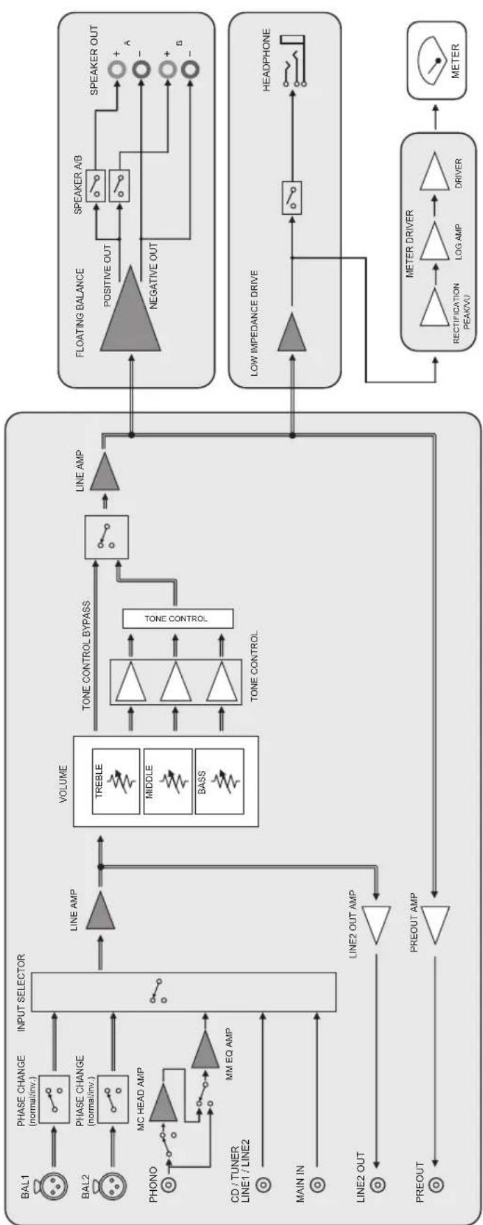
Блok-cхema
Akyctnueckne xapaKTepeNtIKN
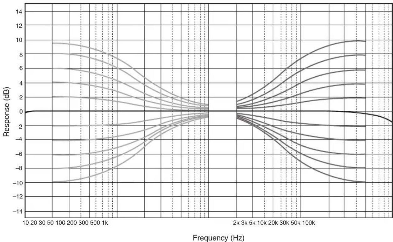
XapaKTePncTnK nperynnpOBKn Tem6pa
Ko3ΦHnueHT HeJIHHeiHbIX mCKaXeHHI

Ko3ΦmUeHT HeJIHHeHbIX mCKaXeHn (PHONO)
Bo3MOxHbIe HencnpaBHOCTn n cnoCo6bl nx yCTpaHeHna
EcJIN daHHbI aIIHapar pa6oTAc HnPaBnIbHO, cm. Ta6JIuY HnKc. EcJIN HeHCnPaBIOCTb He yKa3aHa B Ta6JIuC He HIn Bbl Ic CMOrJIH ycTaPiHTbc, cIeIy HnCTpyKuHm Ta6JIuIbI, OTKIOHTe aIIHApA, OTCOeIHHTe BnIKy ChIOBOrO Ka6JIa H 6paHTtccB K 6JIHKaIIChMBy ABTOH3OBaHIOMy DJIepy HIn B ccpBNCbI UcHtp YamaHa.
| Héncπrabnóctb Pηm | Húna Cnpoc6 yctpahanenry | Cm. ctrp. | |
| Питанные не вкlioуаетс. | Слобов Кабел He полюочen K разьему AC IN на занд� панелей илne Вкlioуен в розту лесенhoe.TOKa. | Порожичite салобovй кабел cootbetCTbyuizimMb obpaazom. | 218 |
| Данный anecdarat полобэрся слььному лесатричесму Нарразжени OT bheшних Источников (нарразмер, молпя панлhoe CTstutceckoe лесатричесТВ). | Быклочite anecdarat, отоедине вкlioу салобог Кабел OT розту лесенгore.TOKa, поождITE okono 30 sekунд, a 3aTe m Chobа рорлочite anecdarat. | - | |
| Miraet Иndikatop (питанные) на зандай панели. | Быla aktnibinровансхема заштейпи из-За корOTКОТЗамыkaняи T.D. | Убадиесь, чTO р罗вда салонок He сорписаотся дугс Дугом плп He замкичытб корOTКС Зддд панель duAnHORO anppapata, n 3aTe m ChOBа BKIOUHTe ПИТANHE anppapata. | 214 |
| ИмeeТся пrobлесma с bHytrpenHIMMсхемам duAnHORO anppapata. | Отоединite влку салobог Кабел OT розту сддд панELу He zamkhytBuKorOTKС Зддд панELь duAnHORO anppapata, n 3aTe m ChOBа BKIOUHTe ПИТANHE anppapata. | - | |
| Кordа anecdarat VKlioquen, мiraet Иndikatop INPUT и уравенberryromkoctn chinkaetcra. | Быla aktnibinровансхема заштейпи из-За корOTKОТЗамыkaняи T.D. | Убадиесь, чTO р罗вда салонок He сорписаотся дугс Дугом плп He замкичытб корOTKС Зддд панELь duAnHORO anppapata, n 3aTe m ChOBа BKIOUHTe ПИТANHE anppapata. | 214 |
| 3Byk He cnblshen. | Кабел BxOda/BxOda Былп полJOUchENbHe nprapabINlbNo. | Правиьно роцлJOUCHTE Kabel.Есян сицраэность coхраяETС, kabelen monуT bdydefeKTbIMN. | 212 |
| He blyн blybran cootBETCTByuIichi nICTouHnik. | С пошью салектора INPUT на занд� панелей (плл odноги иЗ салекторых khanokи ictouchika BxodHORO cInHala Na lyltte Dy) bbypeite cootBETCTByuichi nICTouHnik BxodHORO cInHala. | 204, 208 | |
| Салектор SPEAKERS yctahoblen B noLOJeHne OFF. | YctahobNTe canelkTspSPEAKERS B cootBETCTByuoiue pnoJoxHne. | 203 | |
| Кабел КOLOHOK noDklOUChENbHeprapabINbNo. | Убадиесь в ТOM, чTO Kabelen КOLOHOK noDklOUChENbHeprapabINbNo. | 214 | |
| 3Byk HeoЖиданho otknlouaetcra. | Быla aktnibinровансхема заштейпи из-За корOTKОТЗамыkaняи T.D. | Убадиесь, чTO р罗вда салонок He сорписаотся дугс Дугом плп He zamkhytBuKorOTKС Зддд панELь duAnHORO anppapata, n 3aTe m ChOBа BKIOUHTe ПИТANHE anppapata. | 214 |
| Невозимно отreylmpobatb уравенberryromkoctn. | Вариант MAIN DIRECT Быбpanв в Качебе IMTOUHKNa BXODHORO cInHala. | Отreylmpuyte grpOMKOCTb Ha noDklIOUChENHOM komOnHeNTe.Лобно рdokлJOUCHTE BheushniнkomOnHeNT K nape BxodHix THe3d, OTlinnybIX OT rHe3d MAIN IN, a 3aTe m BlybePitte COOTBETCTByuoiu nICTouHnik BXODHORO cInHala. | 204 |
| 3Byk cnblshen n3 колонку только odhoro kaHana. | Восprion3BOJDAIII KOMIOHENT IINI KOLIOHNI noDklIOUChENbHeprapabINbNo. | Убадиесь в ТOM, чTO OHI noDklIOUChENbHeprapabINbNo.Есян сицраэность coхраяETС, kabelen monуT bdydefeKTbIMN. | 212 |
| Баланс уравяг РомкOSTп можду правои и levoй кOLOHКоннacBoHастpoeh He nprapabINbNo. | Настое balaNC уравяг РомкOSTп можду правои и levoй кOLOHКоннacBnomIoTHIO | 204 | |
| Hemcnpabnoctb Пич | Пивова + И - на усilптеле пьп кOLJOнкх рОДКЛIOчЕны C HENРавильно пОлрноctы. | ПОдКЛIOчITE пьвова кOLJOнok с правильно пОлрноctы + И -. | 214 |
| Спьшен Гудануй 3вук. | Кабел BxODa/BxOda 6bln ПОдКЛIOчЕны HENPABINbNo. | Првавиьно рОдКЛIOчITE Кабел.Если HENcPabnBocSt coxpaHЯETC, kabelen MOrγT 6blt DepeKTHbIMN. | 212 |
| ПОНТВАБЕТЕ БЕЗAZEMLEЧЕРTEМINANGLND. | ПОдКЛIOчITE пОнггьВATEЛК TepMinanly GND Данного annapata. | 212 | |
| Восрочеведения уадиоигнала с komпонента, полкюочen Horo K Bxodнье rHeZda BAL 1 till BAL 2, 3bUyHIT nckaxgenho. | Уровьс СИГнада в СИММЕТричны BXODнбг rHeZdax Ппевышает дОуSTимь BXODногу уровь. | Если уровь сИгнада в СИММЕТRIчны BXODнбг rHeZdax TINa XLR Ha NOДКЛIOчEHOM BOCPONIЗВODЯшем KMПОнентe BДBA pa3a 6Oьше по сравени-c HeCIMMМETriчны mRheZdams RCA, yctahOBITE cseKTopOT ATTENUATOR, paoNOJoxhenHy bng BDxOHDMyr HeZdAmi, B noLOXGENHc ATTT (-6 nb). | 216 |
| В пошкх час tax OTCYCTBYeT rIy6bHa, korдь Вьбрано знayени BAL 1 till BAL 2. | Неверhoe знayени пОлрноctи. | Быберite праВиьную пОлрноctь cnomOuSbO cseKTopa PHASE. | 216 |
| Восрочеведения уадиоигнала ИСКAZЕно пьп пОслuyшвани полкюочenHoro CD-прогьвателя пьmarHTOfoha chepez hayшник (поркюочны к CD-прогьвателя пьmarHTOfohy). | ПИТанne annapata BAkLIOчeHo. BKIOUчte PIIITAHne annapata. 202 | ||
| Уровь ГromKOSTN BVININOBOI ПlaCTINHCSclshkom HN3Kni. | ПepeKЛIOчATEЛ PHONO Na nepeДнe панeу luctANOBlen B HENPABINbHOe NOLOXeHne. | ПepeBeDITE NepeKЛIOчATEЛ PHONO B NOLOXeHne MM ИлMC B COOTBETCTBUN C TINOM MaRHTHOn I rOJOBKN 3ByKOCHIMATEJIЯ пОргьВATeJIa. | 205 |
| ПульТ ДУ не равотаert habлжашим образам. | ПИльТ ДУ IncPONb3уETc 3a NepeДнe пaHeу luctAna3OHa. | ПИльТ ДУ NOJoxhen IncPONb3OVAbC8 N pepeДeax MAKCImaJIbHORO pACCTOraHry 6 М И РODУЛOM He bonee 30 rpaJycob BHeOCEBOr OTKNoHEnHry OT ceHCopa D'Ha npeDne NaHeII. | 210 |
| ПЯрмoe noPadaHne coNHEuHbIX luee Илс OCBSeHcHry (OT INHBePterHoi PhyopecTeHTHOI pAmmb, CTpo6OckOJa I T.D.) Ha ceHCOP D'Ha npeDne NaHeII. | Изmedite oprieNTaizko IVSTOchNka CBet aIIIпОLOXeHne annapata. | - | |
| Раразжehнble 6bataeКи. ПOMeHajte ACE 6bataeKи. 210 |
TexHnueckoe 6cnyxmbaHne
Bokobbie naHei c 3epKaIbHbIM nOKpbITnEM
PeKOMHeYeTcHIOJIb3OBaTB YnCTBIIyIO caJIqTeKY, aHaIOTnHyIO caJIqTeKam IJIA φopTeHHaHO.
Дугпе NOBepxHoctn
He HcIOJIb3yIte IJINHCTKN XHMHueckne BeIEeCTBa, TaKHe KaK 6eH3HH HIN pa36aBHTeJIb. B IpOTHBOM cIJyae 9TO MoKeT IOBpeIHTb IOBepxHOCTH. IIpoTHpaIte IOBepxHOCTM MRTKoI cyXO TKAHbIO.


