
Stage A6002 - Receiver JBL - Free user manual and instructions
Find the device manual for free Stage A6002 JBL in PDF.
| Product type | 2-channel audio amplifier |
| Brand | JBL |
| Model | Stage A6002 |
| RMS power at 4 ohms | 60 W per channel |
| RMS power at 2 ohms | 70 W per channel |
| Bridged RMS power at 4 ohms | 140 W |
| Frequency response | 20 Hz - 20 kHz at -1 dB |
| Signal-to-noise ratio | >75 dB |
| Total harmonic distortion | <1% |
| Fuse rating | 20 A |
| Power supply | 9 - 16 V DC |
| Idle current consumption | <1.0 A |
| Dimensions (H x W x D) | 95 x 230 x 190 mm |
| Weight | 1.16 kg |
| Inputs | High level, line level (RCA), remote (REM) |
| Speaker outputs | Screw terminals (L+, L-, R+, R-) |
| Selectable crossover filters | Low-pass (LPF), full-range (FULL), high-pass (HPF) |
| Bass equalizer | Boost up to +12 dB, adjustable center frequency |
| Protections | Overvoltage, undervoltage, short circuit, overheating |
Frequently Asked Questions - Stage A6002 JBL
User questions about Stage A6002 JBL
0 question about this device. Answer the ones you know or ask your own.
Ask a new question about this device
Download the instructions for your Receiver in PDF format for free! Find your manual Stage A6002 - JBL and take your electronic device back in hand. On this page are published all the documents necessary for the use of your device. Stage A6002 by JBL.
USER MANUAL Stage A6002 JBL
JBL Stage A6002/A6004/A9004/A3001 DC Owner's Manual
JBL Stage A6002/A6004/A9004/A3001 Mode D'emploi
JBL Stage A6002/A6004/A9004/A3001 Manual de Propietario
JBL Stage A6002/A6004/A9004/A3001 Manual do Propietario
JBL Stage A6002/A6004/A9004/A3001 Manuale Utente
JBL Stage A6002/A6004/A9004/A3001 Bedienungsanleitung
JBL Stage A6002/A6004/A9004/A3001 pykoBoDCTBO noIb3ObaTeIa
JBL Stage A6002/A6004/A9004/A3001 Bruksanvisning
JBL Stage A6002/A6004/A9004/A3001 Kayttöohjeet
JBL Stage A6002/A6004/A9004/A3001 Instrukcja Obstugi
JBL Stage A6002/A6004/A9004/A3001 Handleiding
JBL Stage A6002/A6004/A9004/A3001 Betjeningsvejledning
JBL Stage A6002/A6004/A9004/A3001 取級說明書
JBLStageA6002/A6004/A9004/A3001社用者
JBL Stage A6002/A6004/A9004/A3001 用户手册
JBL Stage A6002/A6004/A9004/A3001 拥有者手册
JBL Stage A6002/A6004/A9004/A3001 Panduan Pengguna
JBL Stage A6002/A6004/A9004/A3001 Kullanim Kilavuzu
EN
FR
ES
PT
IT
DE
RU
SV
FI
PL
NL
DA
JP
KO
CHS
CHT
ID
TR
THANK YOU FOR YOUR PURCHASE . . .
Your JBL product has been designed to provide you with the performance and ease of operation you would expect from JBL.
- Please lake time to read your owner's manual in its entirety before operating or installing your amplifier.
-
Keep the owner's manual for your amplifier in your glove compartment along with the owner's manual for your car.
-
Put your amplifier sales receipt with other important documents in order to expedite warranty service if needed.
ABOUT THE MANUAL
This manual describes general installation guidelines and operation instructions. However, please note that proper installation of mobile audio and video components requires qualified experience with mechanical and electrical procedures. If you do not have the knowledge and tools to successfully perform this installation, we strongly recommend consulting an authorized JBL dealer about your installation options. Keep all instructions and sales receipts for reference. Consider this manual as an indispensable feature of your amplifier.
EN
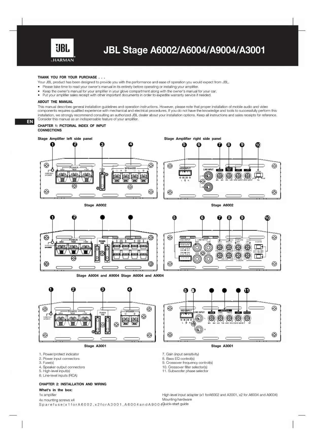
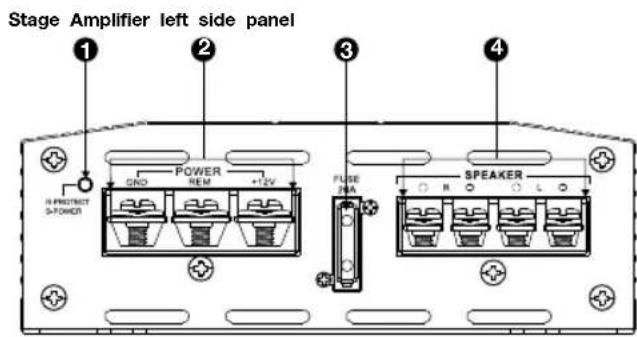
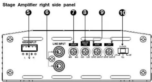
CHAPTER 1: PICTORIAL INDEX OF INPUT CONNECTIONS
Stage A6002
Stage A6002
Stage A6004 and A9004 Stage A6004 and A9004


Stage A3001
Stage A3001
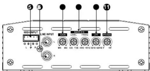
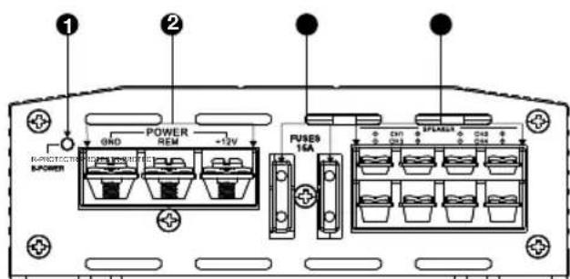
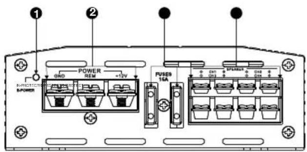
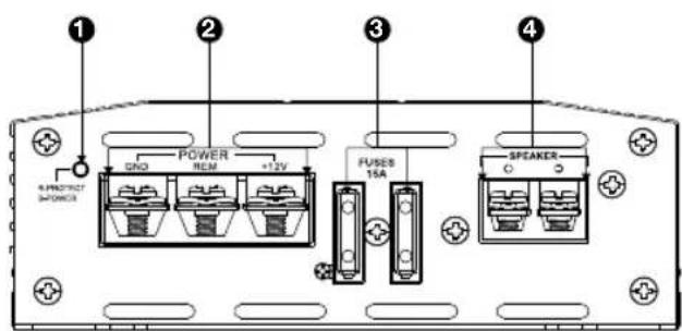
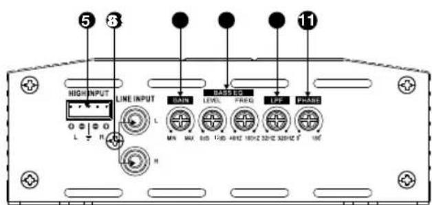
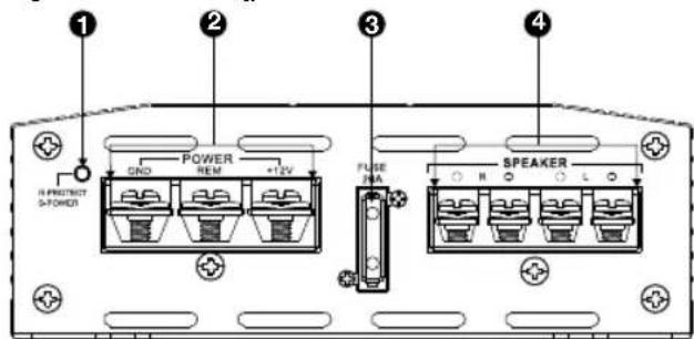
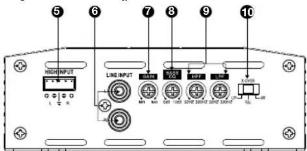
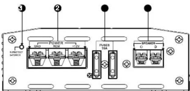
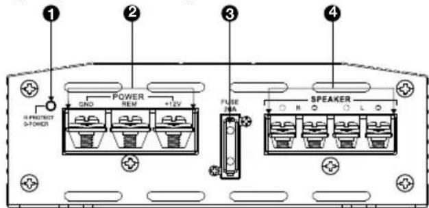
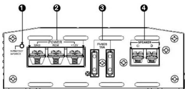
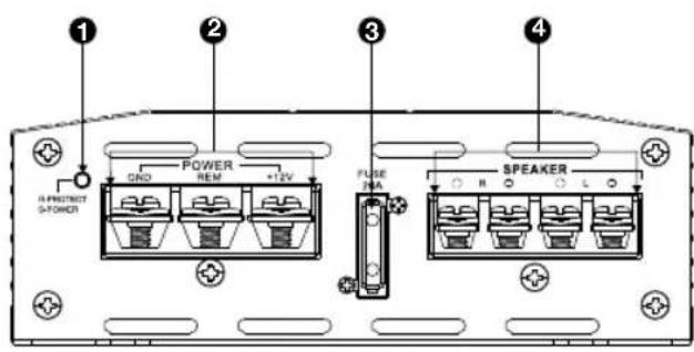
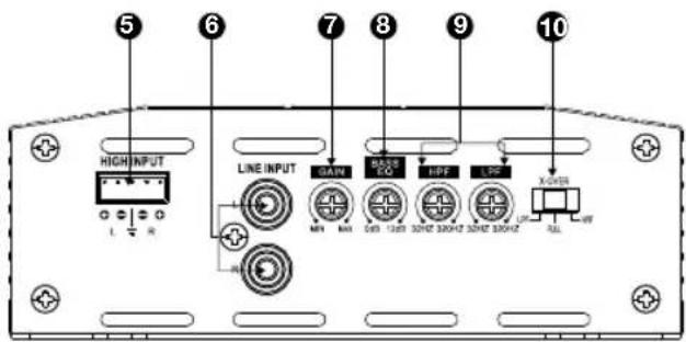
- Power/protect indicator
- Power input connectors
- Fuse(s)
- Speaker output connectors
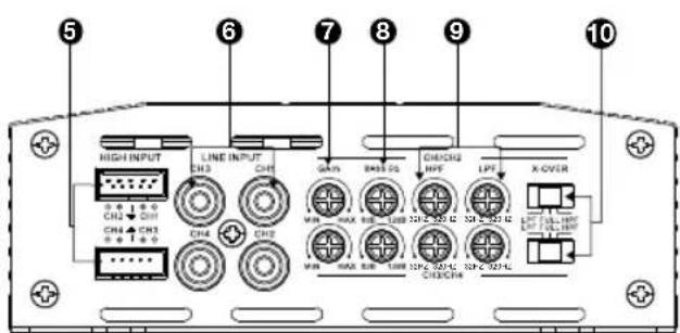
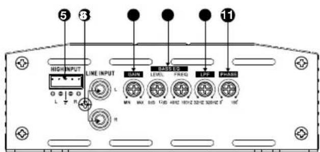
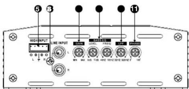
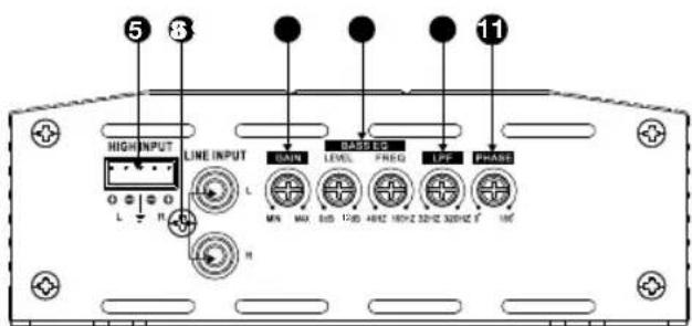
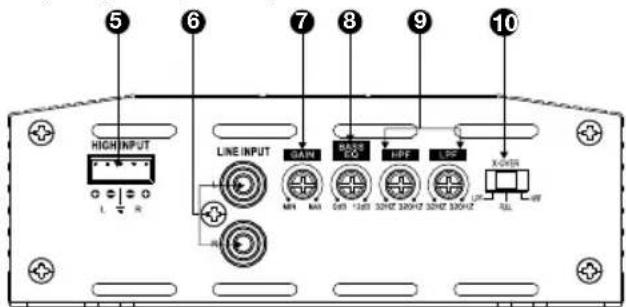
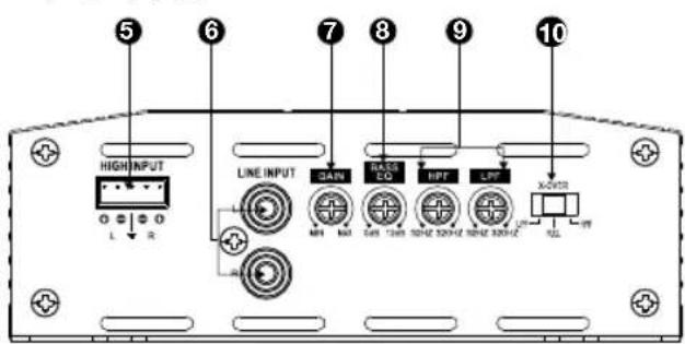
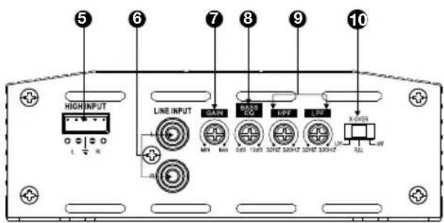
- High-level input(s)
-
Line-level inputs (RCA)
-
Gain (input sensitivity)
- Bass EQ control(s)
- Crossover frequency control(s)
- Crossover filter selector(s)
11.Subwoofer phase selector
CHAPTER 2: INSTALLATION AND WIRING
What's in the box:
1x amplifier
4x mounting screws x4
Sparefuse(x1forA6002,x2forA3001,A6004andA900Quick-start guide
High-level input adapter (x1 forA6002 and A3001, x2 for A6004 and A9004)
Mounting hardware
Precautions:
IMPORTANT: Disconnect the vehicle's negative (-) battery terminal before beginning the installation.
Always wear protective eyewear when using tools.
- Choose a safe mounting location, away from moisture. Check clearances on both sides of a planned mounting surface. Be sure that screws or wires will not puncture brake lines, fuel lines, or wiring harnesses and that wire routing will not interfere with the safe vehicle operation. Use caution when drilling or cutting in the mounting area.
- When making electrical connections, make sure they are secure and properly insulated.
If you must replace any of the amplifier's fuses, use the same type of fuse and current rating as the original.
- To keep the amplifier cool, choose a location that provides enough air circulation, such as under a seat or in the trunk.
- Do not mount the amplifier with the heat sink facing downward, as this interferes with cooling.
- Mount the amplifier so that it will not be damaged by the feet of backseat passengers or shifting cargo in the trunk, and so that it remains dry.
- Using the amplifier as a template, mark the locations of the holes on the mounting surface.
- Drill pilot holes in the mounting surface.
- Attach the amplifier to the mounting surface with four appropriate mounting screws (not included). Recommended: #8 Phillips-head sheet metal screws.

NOTE: You may find it more convenient to make all of the connections to the amplifier before you permanently mount it.
Power/protect indicator:
The light will illuminate in blue when the amp is receiving power and playing. The indicator will illuminate in red if the amp enters Protect mode in the event of conditions such as over/under voltage, short circuit, amplifier output circuit failure, or excessive heat.
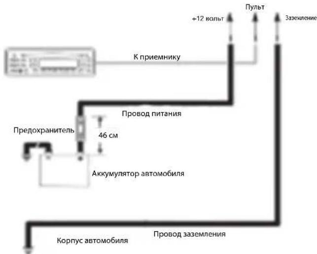
Power Input Connectors:
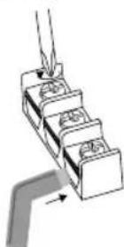
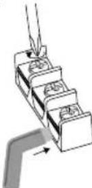
Power: Run power wire from the +12V input to the positive terminal of the vehicle's battery. Insert bare wire into the terminal on the amplifier, then tighten the setscrew with a Phillips screwdriver.
- Install an appropriate fuse holder and fuse (20A minimum for Stage A6002 and 30A minimum for Stage A6004 and A3001, and 40A minimum for A9004) within 18^ (457mm) of the battery. Make sure the wire is not damaged or pinched during installation. Install protective gommets when routing wires through the bulkhead or other sheet metal. Use larger-gauge wiring for longer runs.
- o Stage A6002 minimum wire size: ≥ 10 gauge
- o Stage A6004, A9004, A3001 minimum wire size: ≥ 8 gauge
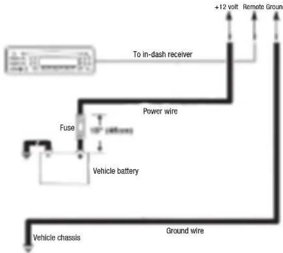
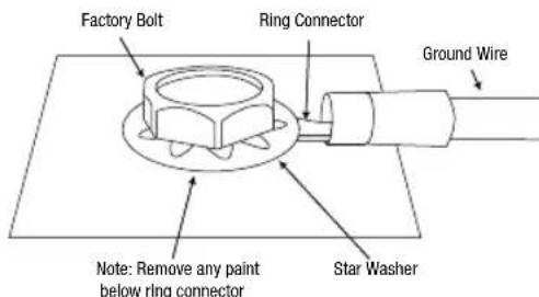
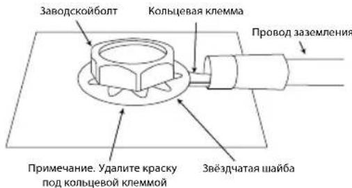
Ground: Run a wire (the same gauge as the power wire) from the GND input to a factory bolt in the vehicle's chassis (see illustration below). NOTE: Remove any paint from the chassis for best contact. Use a star washer below the ring connector for a secure connection.
Remote: Connect a 20-gauge wire from the "Remote Out" lead of the source unit to the REM input. This lead turns the amplifier on when using low-level input signals. If your stereo has no "Remote Out" lead, connect the amplifier's REM input to switched accessory power.
Fuses:
- Replace only with fuses of the same amperage:
pStageA6002:20A
Stage A6004 and A3001: 15A x 2
o Stage A9004:20A x 2
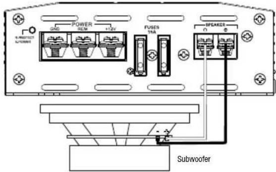
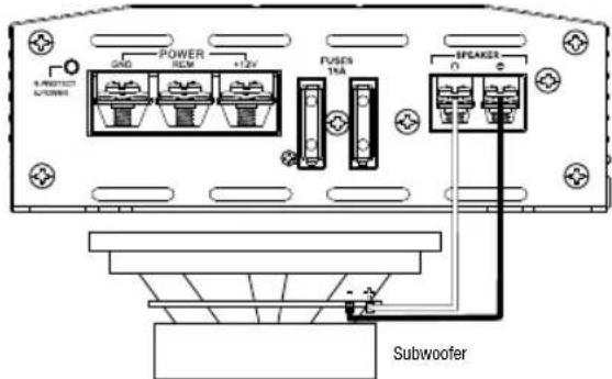
- Speaker Output Connectors:
Connect the speakers to these terminals, observing proper polarity (connect each speaker's positive (+) lead to the appropriate positive (+) terminal, and negative (-) lead to the appropriate negative (-) terminal.
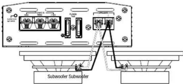
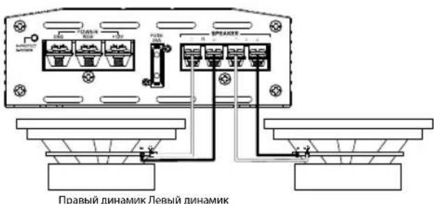
Stage A6002
The Stage A6002 features L+, L-, R+, and R- terminals.
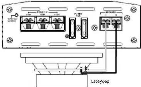
- 2-channel operation: Connect the left speaker to the L+ and L- terminals, and the right speaker to the R+ and R- terminals.
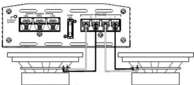
Right speaker Left speaker
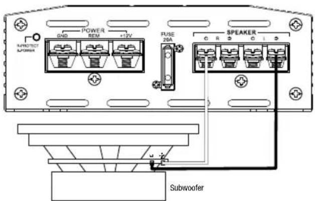
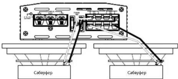
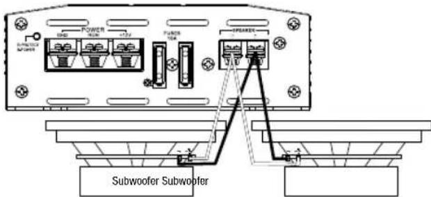
a Bridged operation: Connect the positive wire from the single speaker or subwoofer to the + terminal, and the negative wire from the speaker or subwoofer to the L- terminal.
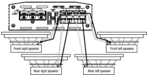
Stage A6004 and A9004
- The Stage A6004 and A9004 feature Channel 1 +/-, Channel 2 +/-, Channel 3 +/-, and Channel 4 +/- terminals.
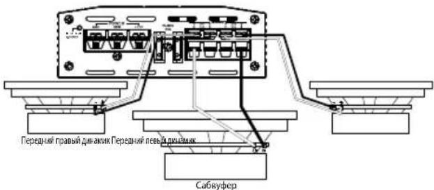
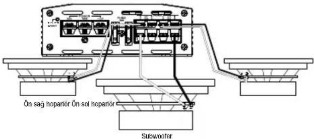
- 4-channel operation: Connect the front left speaker to the Channel 1 + and - terminals, and the front right speaker to the Channel 2 + and - terminals. Connect the rear left speaker to the Channel 3 + and - terminals, and the rear right speaker to the Channel 4 + and - terminals.
- 3-channel operation: Connect the stereo speakers to the Channel 1 and Channel 2 terminals, as described above. Connect the single speaker's + lead to the Channel 3 + terminal, and the - lead to the Channel 4 - terminal.

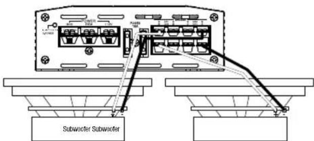
- 2-channel (bridged) operation: Connect one speaker's + lead to the Channel 1 + terminal, and the - lead to the Channel 2 - terminal. Connect the other speaker's + lead to the Channel 3 + terminal, and the - lead to the Channel 4 - terminal.
Stage A3001
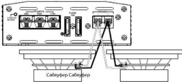
The Stage A3001 features a positive (+) and negative (-) terminals. To power a single subwoofer, connect the subwoofer's positive (+) wire to the positive (+) terminal, and the subwoofer's negative (-) wire to the negative (-) terminal.
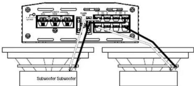
To power two subwoofoers in parallel, connect one sub's positive (+) and negative (-) leads to the positive and negative terminals of the other sub, then connect that subwoofer's positive (+) wire to the positive (+) terminal, and the subwoofer's negative (-) wire to the negative (-) terminal.
NOTE: Minimum speaker impedance for stereo full-range and subwoofer operation is 2 ohms. Minimum speaker impedance for bridged operation is 4 ohms.
- Line-level inputs and outputs (RCA):
If your source unit offers preamp outputs, connect to the L and R (A6002 and A3001), or CH1, CH2, CH3, and CH4 (A6004 and A9004) inputs using RCA patch cables.
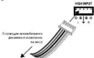
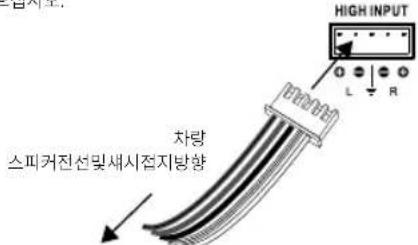
High-level audio input:
If your car audio system's head unit does not have line-level outputs: Connect the white, white/black, gray, and gray/black wires of the included high-level input harnesses to the front and/or rear speaker output wires of your car audio system's head unit (splice crimps not included), and the black wire to vehicle chassis ground. Then plug the high-level harness into the Stage amplifier's high-level input.
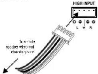
Important: Some factory-installed audio system amplifiers include electronic filters that limit the amount of bass sent to the system's smaller speakers. This filtering will adversely affect the Stage amp's performance. To get the most bass possible from your Stage amp, splice the high-level harness into the factory system speaker outputs that are connected to the system's largest speakers (the ones designed to reproduce the most bass).
- Input sensitivity (GAIN):
Input level controls. Use these to match the amp's input sensitivity to the output level of your source unit. See Setting the input levels in Chapter 3 for a recommended adjustment procedure.
Crossover filter selectors (X-OVER):
Let you choose the crossover filters for your system (the Stage A3001 filter is low-pass only).
- LPF: Low pass. Choose this setting if you're connecting a subwoofer(s), or want to provide a low-pass filter for separate mid-bass speakers.
FULL: Full range. Choose this setting if you're connecting full-range speakers, and not using a subwoofer in your system.
HPF: High pass. Choose this setting to prevent low bass from reaching midrange or full-range speakers when you're using a subwoofer in your system. (See setting the crossovers in Chapter 3.)
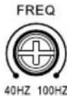
Crossover-filter frequency controls (FREQ):
Turn the dials to the left to lower the crossover point, and to the right to raise the crossover point. Crossover point settings vary by listener preference.
CHAPTER 3: OPERATIONS
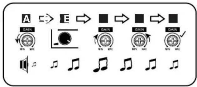
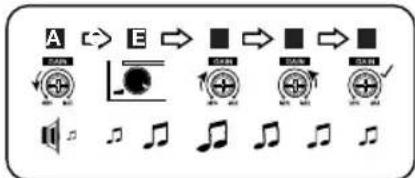
Setting the input levels:
To match your amplifier's input sensitivity (gain) to your source unit's output level, we recommend the following procedure:
A. Turn both input level controls counterclockwise to MIN (minimum).
B. Play a dynamic music track through your source unit. Turn the source unit's volume control to the 3/4 position.
C. Turn the front input level control dial clockwise towards MAX until you hear distortion in the music (it's no longer clear).
D. Slowly turn the front level input control dial counterclockwise until the music sounds clear again.
E. Your front input level is now correctly set. Repeat this process with the rear channels.
Setting the crossover
Properly setting crossover filter selectors optimizes frequency distribution for efficient speaker operation and best sound.
Step 1: Use the slider controls to select low-pass (LPF), FULL, or high-pass (HPF).
- LPF: Low pass. Choose this setting if you are connecting a subwoofer(s) or want to provide a low-pass filter for separate mid-bass speakers.
FULL: Full range. Choose this setting if you are connecting full-range speakers and are not using a subwoofer in your system.
HPF: High pass. Choose this setting to prevent low bass from reaching midrange or full-range speakers when you are using a subwoofer in your system.
Step 2: Use crossover-filter frequency controls to adjust crossover point settings for coaxial speakers and subwoofoers to suit listener preference. Turn the dials to the left to lower the crossover point and to the right to raise the crossover point. Exact crossover settings for coaxial speakers and subwoofoers finally depend on your listening preferences. NOTE: crossover point does not apply in FULL mode.
Selecting the subwoofer phase
With the Stage A3001, you can choose a subwoofer phase output of 0^ or 180^ . To check your sub's phase, play music with lots of bass and listen as another person slowly turns the dial back and forth between 0 and 180 degrees. The correct setting is the one that gives you more bass. If you don't detect any real difference, leave the dial in the 0 setting.

CHAPTER 5: SPECIFICATIONS
| Model | RMS power @ 4 o h m s | RMS power @ 2 o h m s | RMS bridged power @ 4 ohms | Total peak power | Frequency response | Maximum high input signal level | High input maximum sensitivity | Maximum line input signal level | |
| Stage A6002 80W | 70W | 140W | 280W | 20Hz - 20kHz @ -1 dB | 12V | 0.5V | 5V | ||
| Stage A6004 | 60W | 70W | 140W | 560W | 20Hz - 20kHz @ -1 dB | 12V | 0.5V | 5V | |
| Stage A9004 | 90W | 110W | 220W | 880W | 20Hz - 20kHz @ -1 dB | 12V | 0.5V | 5V | |
| Stage A3001 | N/A | 300W | N/A | 600W | 10Hz - 320Hz @ -3 dB | 12V | 0.5V | 5V | |
| Model | Line input signal maximum sensitivity | Line-in signal-to-noise ratio (reference to 1 watt) | THD+ N at rated power (20Hz - 20kHz) | Fuse size | Dimensions (H x W x D) | Weight | Operating voltage | Quiescent current draw | |
| Stage A6002 | 0.2V | >75dB | <1% | 20A | 95 x 230 x 190 (mm) | 1.16kg | 9-16V | <1.0A | |
| Stage A6004 | 0.2V | >75dB | <1% | 2 x 1.5 A | 95 x 260 x 190 (mm) | 1.381kg | 9-16V | <1.2A | |
| Stage A9004 | 0.2V | >75dB | <1% | 2 x 2.0 A | 95 x 325 x 190 (mm) | 1.806kg | 9-16V | <1.5A | |
| Stage A3001 | 0.2V | >75dB | <1% | 2 x 1.5 A | 95 x 313 x 190 (mm) | 1.609kg | 9-16V | <1.5A | |

HARMAN International Industries, Incorporated 8500 Balboa Boulevard, Northridge, CA 91329 USA www.jbl.com
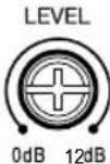
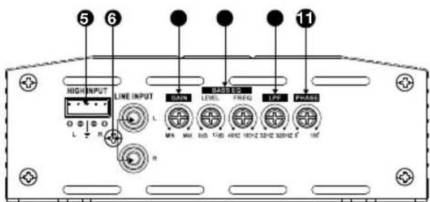
Bass EQ level and frequency:
You can increase the bass output of your system with the Bass EQ feature up to +12dB. Turn the LEVEL dials to the right to increase the bass output.

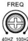
The Stage 3001A also lets you choose the center frequency of the bass boost - the frequency that receives the most boost effect. Turn the FREQ dial to the right to adjust the center frequency. The frequency you choose depends on your listening preferences.
CHAPTER 4: TROUBLESHOOTING
PROBLEM: No audio and POWER INDICATOR is off.
CAUSE and SOLUTION: No voltage at BATT+ and/or REM terminals, or bad or no ground connection. Check voltages at amplifier terminals with VOM.
PROBLEM: No audio and PROTECT INDICATOR flashes every 4 seconds.
CAUSE and SOLUTION: DC voltage on amplifier output. Amplifier may need service; see enclosed warranty card for service information.
PROBLEM: No audio and PROTECT INDICATOR is on. CAUSE and SOLUTION: Amplifier is overheated. Make sure amplifier cooling is not blocked at mounting location. Verify that speaker-system impedance is within specified limits. Or, there may be voltage greater than 16V (or less than 8.5V) on BATT+ connection. Check vehicle charging system.
PROBLEM: No audio and PROTECT and POWER INDICATORS flash. CAUSE and SOLUTION: Voltage less than 9V on BATT+ connection. Check vehicle charging system.
PROBLEM: Distorted audio.
CAUSE and SOLUTION: Gain is not set properly. Check INPUT LEVEL setting. Check speaker wires for shorts or grounds. Amplifier or source unit may be defective.
PROBLEM: Distorted audio and PROTECT INDICATOR flashes. CAUSE and SOLUTION: Short circuit in speaker or wire. Remove speaker leads one at a time to locate shorted speaker or wire, and repair.
PROBLEM: Music lacks dynamics or "punch."
CAUSE and SOLUTION: Speakers are not connected properly. Check speaker connections for proper polarity.
PROBLEM: Amplifier fuse keeps blowing.
CAUSE and PROBLEM: The wiring is connected incorrectly or there is a short circuit. Review installation precautions and procedures in manual. Check wiring connections.
PROBLEM: Engine noise—whining or clicking—in system when the engine is on.
CAUSE and PROBLEM: Amplifier is picking up alternator noise. Turn down gain. Move audio cables away from power wires. Install an alternator noise filter on power line between battery and alternator. Check ground connections on the amplifier since a loose or improper ground is one of the main causes for extraneous noise in your audio system.
© 2018 HARMAN International Industries, Incorporated. All rights reserved.
JBL is a trademark of HARMAN International Industries, Incorporated, registered in the United States and/or other countries. Features, specifications and appearance are subject to change without notice.
MERCI POUR VOTRE ACHAT...
Stage A6004 et A3001:15 A x 2
Stage A9004:20A×2
HARMAN International Industries, Incorporated 8500 Balboa Boulevard, Northridge, CA 91329 USA www.jbl.com
© 2018 HARMAN International Industries, Incorporated. Tous droits réservés.
HARMAN International Industries, Incorporated 8500 Balboa Boulevard, Northridge, CA 91329 USA www.jbl.com
© 2018 HARMAN International Industries, Incorporated. Todos los derechos reservados.
Stage A6004 e A9004 Stage A6004 e A9004

Stage A3001
Stage A3001
HARMAN International Industries, Incorporated 8500 Balboa Boulevard, Northridge, CA 91329 USA www.jbl.com
© 2018 HARMAN International Industries, Incorporated. All rights reserved.
JBLé marca registrada da HARMAN International Industries, Incorporated, registrada nos Estados Unidos e/ou em outros paises. As caracteristicas, as espécografías e o design就是在jusitadosa alteración semavoidopreviousi.
GRAZIE PER AVERCI SCELTO...
HARMAN International Industries, Incorporated 8500 Balboa Boulevard, Northridge, CA 91329 USA www.jbl.com
© 2018 HARMAN International Industries, Incorporated. All rights reserved.
HARMAN International Industries, Incorporated 8500 Balboa Boulevard, Northridge, CA 91329 USA www.jbl.com
© 2018 HARMAN International Industries, Incorporated. All rights reserved.

Ppabar naHelb ycHntela Stage
Stage A6002
Stage A6004 n A9004 Stage A6004 n A9004

Stage A3001
Stage A3001
- INHINKATOP NITAHM/3aunTb
2.BxOaHbIe pa3bEmblnTtHaH
3.П repdoхарнелу
4.BbXoHbIpepa3beMbIINIOKIOOeHHNINHAMNKOB - BbICOKOyPOBHeBBIe BXOJIb
- NHeBbE BxOdbi (RCA)
7.YCINJEHHe(BXOHNARYBCTBNTeJIbHOCTb)
8.YnpabneHnE 3KBaIaI3epoMbaca
9.YnpabJIeHHe YacToTOn KpoccoBepa
10. Npeeknokatenn KpoccoBepa
11.Фаob布局nepekniohaTeNbca6Byepepa
PA3ДЛ2: YCTAHOBKA И ПОДКЛЮЧЕНЕ
KOMJIeKT NOCTaBKn:
- INHdkaTOp nHTAHy/3aunTbI:
Kordy ycnntel noynaet nTnAne N BblnoHreBocnp3BcHHe, HnDKATOp rOHT CnHM UBeTom. INhNKATOp 3aROpTCH KAPChbM, ECIN YCNNTe NEPeXoNT B PEXM 3aunTbB CnlyoB O3HNHOHHeN TAKHX RJIeHm, KAKn3bTOHNOHEDOCTaTOHoe HapPKeHHe, KOPOTKOE 3aMbKaHne, C60B BxHOHJUeN yCNNTe NNI nepepepe.
BxOdhblpepa3beMbI NHTaHnA:
MoHocb: COeHHHTpe NPOBOOMI HNTAHRA BXOAD+12B INIOKOTJIeBHHy KEMMYA BTOMOBHLHORO AKKyMnTOpa. BCTABStE HeN3OLIMPOBaHHI PNOBOD, B KEMMY HA YCNITTE, 3ATEM 3aTHHTe YCTAHOBOHHB MHT KPECTOo6p3HOI OTBETKOH
YCTAHOBNTE COOTBCTCYUHNIATPOH npdoxpaHTENn IN npdoxaHHTINb (20 A MHHMmDnIgStage A6002u30 M MHHMmDnIg Stage A6004 N3A3001R 40 AMHHMmDnIg A9004) B npdeIax 457 MM ot aKKMyJITOPa. Y6eJIIEc, yTO BO BPEMN cTAYHOANK nPOBOID He bUII NOBpeXdHnn nepeKat. Pnnpoklanke npobOIOB Hepea npeperopky nn Doytnie Detanl N3 NtCtOBTO METALNA YCTAHABINBAITE 3AUITTHIE BTVIK, Dn npobOKN Ha 6oJIbuee pacctOHaHE mONLb3yTe npobOda BoIbueero KAIINbopa.
oMHHaJIbHbIpa3MeP npObaStage A6002:≥10KaIIb6p oMHHaJIbHbIpa3MeP npObaStage A6004,A9004,A3001:≥8KaIIb6p
3aemnne:coeHNTpe npoBOOM (rakoro kke kaIbpa,TO INpOBOI nTahnBxOD GND (3aemnne) u 3abocckon 60JI B Kcnpyce ABTOMOBUN (CM. NIOCTPAUHO HIXKe).
PIMMEAHNE. Iy uyuHHeN KOtAKTa ydaNTE C KcnpNyca Kpacky.
Ja HaeXHO CoeHnHn MOnbEynte 3Eeaatuyo Wauy IOJ KOLbueBOI KIEMMOI.
Nytb: CoqHnnte npoOoM 20 kaIbpa Bixoc dnn nybta DNY nCTOHmka ayioocHHa n BXoD REM. OTB bIXoD BKHOaET ycHInTeB pIN uCOnJb3OBAHn H3KcypOBHeBbX BxOHy CnHAnOB. Ecn y Bauei CTpeoCNCCTemB HET BixoDa nn pybta DY, noKnIOHTe BxoD REM ycHnne K NITaHIO.
- PpeOxpaHHTeI:
3aMeHHeCTapBle npEdoxpaHHTeTOLbKO npEdoxpaHHTeJIaMn, paccHTaHHbMM Ha aHaIaONuHyK Cnly TOKa: oStage A6002:20B oStage A6004 nA3001;15A×2 oStage A9004:20A×2
BbIXoHbIe pa3beMbI IaI NOKIOUeHn DnHaMKOB:
IIOKIOHNTeINHAMMKK BYXOaAM, COBIOAa NOIPOHOCTb (IOCOEOYINHTE IIOKNOHTeLbHb(+)PBOAO KAKDORIO INHAMKK KA COOTBTCTBYOLOEMI IONOKNOHTeBHOMy(+)BxIOyO,aOTPMUATEBbHb(-)PPOOB- K COOTBETCTBYIOHOMy OTPMUATEBHOmy(-)BxIOyO).
Stage A6002
Stage A6002 mMeT bixOaL+, L-, R+ n R-
-2-KaHaJIbHaBcIcHMe: IIOCoEOJIHHeNIEeBbIINAMHKM BbIXOdAM L+ IN KaHaJIa, a npAbB bINAMHK - K bIXOdAM R+ IN-R-KaHaJIa.
O. Moctobaa cxema: POKKHTNEI NOXNTENbHn npoBOD OT cHoro dHnHAMnVI nIN cABBypepa K bXbOy R+, aOTpNATeNBHn npoBOD O TdHnAMnKA nIN cABBypepa K NEMME L.

Stage A6004 n A9004
Stage A6004 nA9004 mEeT BixOdbI dna KaHana 1 +/-, KaHana 2 +/-, KaHana 3 +/-, n KaHana 4 +/-.
- 4-KaHaJIbHAR cIeTeMa: IopcoeDyHITne neBbI npepDHm DnHAMMK K BbIXoAM KaHIOB 1+u-a npABBn npepDHm DnHAMMK -K BbIXoAM KaHANOB 2+u.- IopcoeDyHITne neBbI 3aHm DnHAMMK K BbIXoAM KaHAnOB 3+u-a npABBn 3aHm DnHAMMK -K BbIXoAM KaHANOB 4+u.

-3-KaHaHbHa CnTeMa:NoKIOKIOHTe CTepeOINHAMMKN K BbXoAMKaHana 1u KaHana 2, KAK ONCAHO BbIue. NOCoEOHNHTe NOJIOHTeBbH npOBd OGDHO rIMAMKaHnK BkXbOy KaHana 3+, aOTPiaeTbHbN npOBd -K BbXOdy KaHana 4-,
-2-KaHaIbHaa(MocToBa)CnTeMa:PiOcEynHITe
NOJIOKHTeBHyPiOBOOd OIOHOrANAMMKA K BbIXOy KaHana 1+ a
OTPiUaTeBHyPiPOBD-KBbIXOyKaHana 2-.PiOcEynHITe
NOJIOKHTeBHyPiOBOOd DpyTOrO PyINAMKKA K BbIXOy KaHana 3+, a
OTPiUaTeBHyPiPOBD-KBbIXOy KaHana 4-
Stage A3001
Stage A3001 IMeET NOIOKHTENbHbI (+) INOTPOATeTbHbI (-) BbIXOdb. OITNATAHcABycepa NOKNIOHnTE NOIOKHTENbHbI NPOBOD (+) KNOIOKHTENbOMy (+) BxHOy, a OTPOATeTbHbI (-) NPOBOd K OTPOATeTbHbOMy (-) BxHOy.
oI npaHnBHO nHTAHm DByx ca6bypepo, NOKIOHMe OINNPOXNTeHbH [+] npOTPAIeHbH [-] pOBOd K NOKIOHtEhOMHy N OTPLAeTHbOMy BbXoDpyrTOc c6bCypea, a 3aTeM NOKIOHtE NIOXNTeHbH [+] npOBd K NOKIOHtEHOMy [+] BbXoDa, a OTPLaTeHbH [-] npOBd C6bCypea K OTPLaTeHbOMy BbXoDy.
PIMMEAHME.1MHNHbHMMNDBHcHnMMKOBdPAOBtBnHOHgANBxHOM CTepcepeKmHpaobToCbCaBycpocomCocTABnT2OM.MHHaHbHMMNpOcHnDMHNAMKOBdPAOBtBmOCTOBOMpeKmVcoCTABnT4OM
- JInHeHbIe BXOdbI N BbIXOdbI (RCA):
Ecm HA HcTOHKe AUYMOCHINBA EeBbXoDJI INPpOyCnITIEJIO, NQKIOHMe I KxOAM L R A602uA3001 mI CH1, CH2, CH3 u CH4(A6004 and A9004) c nmoioucoeDHHnBkKaBeR PCA
- BbICOKoypOBHeBbI ayDNOBXoD:
Ecn y rnoBHOY cTPOHCTBA Baae ABTOMObIbHO ayDIOcNCTMbHET NmHNbHbX bXIObO:
PnKIOHnE6BnI, YEPHO-5eBnI NEPHO-CepBnI PPOBOA BbICOKOyOBHEoB 3JNEKTPOPOBODKN K BxOxDNBM PPOBOAMpepeHrero WmN3ADHeR OINHAMMkA rnoBOHOrO yTOPOBCTBA BAueB ASOMOBuHBo HpyDCNCHCtBMc COeCDHnTcBbHbE 3AKHMJI He prrnaaOTcH, a YEPBnI PPOBOOJK 3a3eMJEHNHO HA Maccy. 3ATEM nKIOHnE TbeBCOKOyPOOBHeYbO JNEKTPOPOBODky K BbICOKOyPOBHEOMy BXOdy ycmnnnTnStage.
Baxho.HeKOTOpbIe 3ABODCKHe yCmHITEnI ayDNOCCTeM IMEOT 3ETKTOHNbIE
fMbTbI, KOTOpBc ORpAHMHBAOT MOHIOCTb H3KHXCACTOT, NcOaJIbEMBX HA MeHec
KpyNtBHe DnAMNK B CHTCTME. 3Ta FnIbTpAUR HERATINHO HOINBNT HA KAECTBO
yCNITENBStage.DnI NOJYHHeH HANBOOE MOnHbIX H3KHXCACTOT OT YCNITENB
Stage NOCDeHNIHTE BICKOPOOBHeYIOPOBDKY K bIXoDAM DnHAMNKOB 3ABODCKON
CCTeMBI, KOTOpBc NOKIOHHeBI K CaBMl BoHIM DnHAMNKAM CHTCTMI
(nPdEHAHCHHHM IBNOCPCNBODEHINHKKXCACTOT).
BxOHaHyBCTBHTeBHoCTb(YCNJIeHHe)
YnpBnHnE BxDhBm CInHAnOM. NcNo3yIe IV dx Ia nPbBdoHN H B COOTBTCTBnE BxDOHn- yBCTBtBnHOCTN YCNHNTENI yPOBnB BxIOHOrO CINHAN A MTOHNIKA aynocnHnA. cM. peKoMeNBoHHaHy npOePyu peryNpOBKn OINCAHA B paanede NaChtpnkya POpEnBn XBOHOro CInHnA R nBaae 3.
-ПepeknioaTeiKpoccoBepa(X-OVER):
P30BbHOT BbVbtpf DnBpBpKoOcOeBaIraBaaepCCTMeI (DnBtPStage A3001 TOBkoI HNkXhCactO).
LPF: nponyck hactot Hnke nporobon hactotbl. Bb6epnte 3ty hactpokky, cnnBbl noknnoaete caBbyepbi) nixoTtbe oeceneHbIbnbpauio c nponyckOMhactot Hnke nporobon hactotbl dnr OtdalnbHexcpeHHe-HnKoHACTOTbHxDHNBMKO8.
FULL:nonHbIaHa3oH hactOT.BbIepHTe 3Ty HacpOxy,ccnbl nKIOJIcHaeTe noHNOIaHa3OHHeINAMMnH He MCNoB3yTe Ca5Bype B CBOE CNCTEME.
HPF: nponyck cactot Bblue npocoboiy cactotbl. Bb6peite aty Hactpoyky dny rpeotopbaenHHnlaaHmHHKxHcTCTB C0eJeHcTObTHbEHN NPHoDnAra3OHHbIe DnHAMMknpnNCHIO3oBAHmB CInCTMeCabBypepa. (CM.padien-HactpOka KpcocOBepa-BIabe 3.)
- PerynTOpbl YacToBkPoccoBepa (FREQ):
NIOBOPAHAIae pyKpyPPOBKN BJIeBO DJIH CHINKHeH NTOH NpeceHNI BnPABO 1y ee NOBbIeHNHa. HAcTPOKn TOKn KpCOoCobepa 3abNCrOT npeiOnTeHN CnyuATeHN.
PA3EN3:3KCNYATAUN
HacrpoKa yPoBnBxOaHoro CunHaJa:
IINPnIeBENHBI CootBTCTBVE BxOHOH HYBCHTBHeTbHIOCTa (yCtHHeN) yCnHNTaJIy IyOBHBA BHXoHOrO CNHAnA INTOHNKAA BYDNOCHNA peKOMEHpyETcBA BInOJHMTb CJEUYOUy IOPOLeEyOy
A. NoBepHMeTe 6a peryIraTopa ypoBHa BXoHOrO CmHana Ha OTMeTky MIN (MmHmMy).
B. BocnpnBaBnTe pHmHMyHy My3kAaHyo KOMOa3uMgpe3 XTOHnA yAnOCmHa. IopepHnre peryTnTrop pomKcT nCTOnHnA ayDnOCmHa BA noJIOXeH 3/4.
C. NOBOPAHAIAE PERIHTOP yOeH BxOJIHO CHTHIA HIEpIH KAHJIOB NO HACOSO CTPEKNE HO HAPABENHEK KO MTETK MAX (MAKIMYM), NOKA 3BYK HE YTPATNT CTCOTY NE NOB8BTCN KCAKAKHNI.
D. MeIeHNO NOBOPaHbAte IepEINHO pyKpyERYrTOPA yOoBHxOHDOrO CnHana IropTb YACOBcI CTpeIKN, NOKA 3ByAHMe My3bIK CHOBa HE CTAHET MCTbM
E. Teneb ypo8eBbXoDHorO CunHana IaI nepeDnHX KAHANOB HAcTPOEH npabNtBHO, NopToPte npoJepyu 3aHnx KaHAnOB.
HacTpoIka KpOcCobepa
PraaHbna HACTPOXnIpeKIOHOJIeTIyIKOCCOBepaONITIMMIMHYET PAcNcEJIHeHAACTOTIaeocneHcyiOoKcKTeBHyOBpOToHINAMIKOBKOBITMIIMMAHBOH3BYYAHNA.
3tan1:InnoBsyTbNo3yKOBbIe NpeKaIOHcATEIN D8 BbOpapeKMA npOnyckA cactot Hnke npocoroi (LPF), nponycka bceX cactot (FULL), nnn nponycka cactot Bblue npocoroi (HPF).
LPF: nponyck cactot Hmke nporoboh cactotbl. Bb6epte 3ty hactpoky,ecnbl bI pNDKIOHaeTe CaBvpebp(b) VNNOTHE Obcne-NTb DnNtpaMIO C nponyckOM HACTOT Hmke nporoboh cactotbl drr OeDnBbIX cpeHO-HmKoHAcTOTbIX dmHAMKOB.
FULL:nonHnIyDnAaONHACrT. Bb6prrte3ryHacrpoKy,ecnBblnoKnHaeTe nHOJnAna3OHbIe DnHAMNKn HHeNCIOJIb3ye CABpypeB CBOEINCKCTME.
HPF: npoxnyck xactot bblue nopotoboi kactotbl. Bb6pmtte 3ty hactpoky dnp
npoDcTBAeCHNnONANHINHNNKxactotB CpOeHCACTOTHNI
PONCDAIANSAHCHIIy HBNAMIK PNPNCNOLsOBAHIN BCACTME CaSByepa.
3Tan 2:InnoIbEyIe peryIaTOBpaCTObl KpoccoBepa IpyerpyPOBn HAcTPOEK TOHNIpeCecHHeIg KOACKaIbHbX DnAHHMkoN CabBycpoB NOI INDINsIyIbIbHe npEDIOHTEH CYaUATENe. IIOOPaHBeIa PyuKpyERpyPOBn BNEBO DNCHKEHrTOckpeCecHHeIg BNpAOIe ee NOBIoUeHNr.ToHHe HACTPOVNNKPCOCCEBPA IIOKCAIVbHbX DnAHHMkoN CABBycpoB 3BaBCNTB KOHEHmITOTe OT BAIIIX npDENoTHKeK KcYcUATENe.
PIMMEAHNE.ToKa nepeceHHe npMmHaeTcB pexMe FULL (nonHbI mna30Hactot).
Bb6opΦa3b1 ca6ByΦepa
VStage A3001MOxHO Bb6paTb pa3OBuB bBxOaCabBypepa: 0^ mN 180°.ItnpnoBepK a3bIcABypepa nocTabe Ha BOCPONB3EHEme My3kYiC bOULIMK KOJIHCTOB M CACOB N CUYAHTe ee, NOKA DpyroY eYIOBEK MEJIEHHO NOBOPA-HaBT PeekKnOHTaBb/0/180 rpaDCOB TYa-06pTHo.PpAunHbHa HAcToPka-Ta, pN KOTopo CNbUHTcB 60blue HnKmX qactOT. EcnB bIe 3ameaTe pAsHHb, octabTe peekKnOHTae B nIOJOKeHHN 0.

YpOBeHbN aCTOTA 3KbanaIaIepa 6aca: BblMOXeTe yBEnHITb 6ac BaIuei CICTeMbI npn nmoOnu 3KbanaIaIepa Ha +12 dl. IopBePHTe peryIaTOp LEVEL bnpabo dnyBeyIaIeHbI 6aca.
Stage A3001 TAKOe no3BONReT Bb6paTb CEHTpaJIbHyo cactOTy ycINHeHg 6aca - cactOTy C MAKcIMaJIbHbIM 6acom. POBepHnre peryIITopFREQ bnpabo dpyerIipOBKn CEHTpAlbHOH cactOTy Bb6paHna cactOTa 3aBcNtOT BTBAHX NpEODnCTEHm.
PA3DEJI4:YCTPAHEHNE HENOLADOK
PPOBJEMA:3Byka Het, INHJIKATOP NITAHIN He ropit. PIPYIMHA N PELIEHEME:OTCCTCTBYET HANPRKHe HbBxOax BATT+WmR REM, 1063a3eMHeNIOXn OTOcTCTByET. PIOBepBe HApRKeHHe Ha BbXoax CYNUMTECNOMOLIOB BOBTOMETPA.
NPOBJEMA:38ykaHET,INMHJNKATOP3ALLNTBIMraeKkqdybe4cekyHb. NPHMNAHPELEHEHnHapokHeHNOCTOHORTOKaHaBxOJeYCNITBIL. YcunntoMOKeHTNotPte6BaTHCbO6CNYkBAHHe;NHDPOMAIOO6OBcNyKBABHM CM.HpNPOXHEHOMRAPaTNIHOMTANOHE.
PPO5EMA:3BykaHET,INHNIKATOPNITAHNROprr.
PIVHNAPELLIEHEY:YcnnnntbIe npperpeny. YbepntcB, TTo HnHrO He
PNPTETCTAYET OXANDEHNIO CYCNNTNE B MECTE YCTAHOBKn. PnpoeBpe, TTO6bl
MNNEADHC NCTEMBI DAnHAMIKOB HaxoDINCR B Pnpenax Hopmbl. NlboKe
HaanpkeHeHne COeJHNNHBM BATT+MOxER 6bbl 60blue 16 B (nn MeHbue 8,5 B). PnpoeBpe CTNEA 3APdKn ABTOMOBN
NPO5EEMA:3pykA HET, INHINKATOPBb 3ALUNITb NNTAHNA MAFIOI. PPNHIMA PELIEUHE:HNAPXHEHe HA COEDHHEN BATT+MEHBUE9B. PnOeBcTO CNTEMY 3apxn ABTOMOVII.
IPOBEMA: NcKaKHe 38ka.
PPI/HHNA PELLHE/NE: YcHHeNHe HAcTpoHo HEnpABuHbNo. IPoOBepTe HAcTpoKy
YPOBH BXOJDHO CmHAnA. IPoOBepTe IcPoBaDnHAMKKOB Ha npDeWet
KoPOTKx 3aMbKAnHm 3a3eMnHg Bo3MOKHa HeCNpABnCtBu yCnNTaRn IN
NCTOHNHa ayDcOcHnHa.
PPOBEMA: VckaeHm38ka, mMrae INHdkATOP SAUHTbl. PPHVHNAPELHEHNE: KOpKoe 3aMbKaHne B pHAMKe Nn PPOBOE. HsIkeAte nPoBaD aHaMMKO B NO OTHOMY, 106bO onpeHMTb DnHAMNK Nn PPOOc C KOpKTOHM 3aMbKAHMe. O6hApyKbN oSpeKpHHbK OMNOHET, OTCPMOHpyME ERO.
PPO5NEMA:My3bke He Xbaatae DnHAMMKNIIN MOLU. PIPHNA H N PELIEHEV: DnAMNKIOKHOHe HnepaBnHO.POBepBo NOJPOHCTCoDBEHNHIN DnAMMKOB.
PNOBEMA: PNOEoXpAHnTeIy yCINTEIe IIOCTOHHN HpeEROPaET.
PPIHNA HPOLEMA: PNOBaIraNoCoEOHNHeHb HnerpaBvHb, Nn Ipn03uHIO
KOPOTKE 3aMbKaHHe, IV3yHMe IpeOcTOPOKHOCTN I pOueDpybYCTAHOBKn,
ONCAHBe B pykOBocTBE. PNOBepBe CoEOHNHeNPOBOBD.
PPOJEMA:UyMdbaratena-BOINMNUEKahbe-BCCTMEpN BKNIOHCHOM
PNUHNA HPOSEMA: Ycunntb npnHmaeT yMm rhepatopa nepemehoro TOKA.ymeHbIte ycHMeHE. NpOeMeCTe ayNDokaBn noJANLIEOT NPoBCODN PNTAHNA. YCANTABOH CINbIb pUyMMrTepeHepaTOPA NEPEMEHHORO TOKA H NIMHO NITAHNA MEXdy AKKyMByTOpOM INrHePATOPOM nepeMHORHO TOKA. PNOBpTE CoepHHeHRA33AEWNEHAR HA yCUNITE, NCKONKBY HERNoTHOE IIN HEPABINbHOE 33AEmHHe HeBETCR OADHON MCHOBHx PnPHN NOCTOPOHHERO WMyBA B ayNDOCCTME.
PA3DEI5:TEXHNUECKNEXAPAKTEPNCNTIKN
HARMAN International Industries, Incorporated 8500 Balboa Boulevard, Northridge, CA 91329 USA www.jbl.com
© 2018 HARMAN International Industries, Incorporated. All rights reserved.
JBL JIITcTc ToabHbM 3hAKOM HARMAN International Industries, Incorporated, 3aepnCtpnoBaHHbM C LCLW w/nn dpynx ctpaHax. FyHKUHN, xapaKTePcTmK IN BHEUNHMOTY MOrT yMeHHTCB 683 yBdOMENHIN.
TACK FOR DITT KOP.
HARMAN International Industries, Incorporated 8500 Balboa Boulevard, Northridge, CA 91329 USA www.jbl.com
© 2018 HARMAN International Industries, Incorporated. All rights reserved.
- Tuloherkkyts (GAIN):
KAPPALE 3: TOIMINNOT
HARMAN International
Industries, Incorporated
8500 Balboa Boulevard.
Northridge, CA 91329 USA
www.jbl.com
© 2018 HARMAN International Industries, Incorporated. All rights reserved.

Lewy panel wzmacniacza Stage
Stage A6002

Prawy panel wzmacniacza Stage
Stage A6002

Stage A6004 i A9004 Stage A6004 i A9004


Stage A3001
Stage A3001
Stage A6004 i A3001: 15 A x 2
o Stage A9004: 20 A x 2
HARMAN International Industries, Incorporated 8500 Balboa Boulevard, Northridge, CA 91329 USA www.jbl.com
© 2018 HARMAN International Industries, Incorporated. All rights reserved.
Stage Versterker linker lijpaneel
Stage A6002
Stage Versterker rechter ijpaneel
Stage A6002

Stage A6004 en A9004

Stage A6004 en A9004
Stage A3001
Stage A3001
High-level audio input:
Crossoverfilter-schakelaar (X-OVER)
HARMAN International Industries, Incorporated 8500 Balboa Boulevard, Northridge, CA 91329 USA www.jbl.com
© 2018 HARMAN International Industries, Incorporated. All rights reserved.
Stage Amplifier venstre side panel
Stage A6002
Stage Amplifier hôjre side panel
Stage A6002
High-level lyd-input:
HARMAN International Industries, Incorporated 8500 Balboa Boulevard, Northridge, CA 91329 USA www.jbl.com
© 2018 HARMAN International Industries, Incorporated. All rights reserved.
HARMAN International Industries, Incorporated 8500 Balboa Boulevard, Northridge, CA 91329 USA www.jbl.com
EQL
© 2018 HARMAN International Industries, Incorporated. All rights reserved.
Stage 宽π 无实部
Stage A6002

Stage A6004 果A9004 Stage A6004 果A9004

Stage A3001

Stage A3001
0 BnIJ T#FJ#T#E: #JH 15 FJ#FJ#FJ#FJ#FJ#FJ#FJ#FJ#FJ#FJ#FJ#FJ#FJ#FJ#FJ#FJ#FJ#FJ#FJ#FJ#FJ#FJ#FJ#FJ#FJ#FJ#FJ#FJ#FJ#FJ#FJ#FJ#FJ#FJ#F

Stage A6004 和 A9004
樂藥藻藻藻藻藻藻藻藻藻藻藻藻藻藻藻藻藻藻藻藻藻藻藻藻藻藻藻藻藻藻藻藻藻藻藻藻藻藻藻藻藻藻藻藻藻藻藻藻藻藻藻藻藻藻藻藻藻藻藻藻藻藻藻藻藻藻藻藻藻藻藻藻藻藻藻藻藻藻藻藻藻藻藻藻藻藻藻藻藻藻藻藻藻藻藻藻藻藻藻藻
HARMAN International Industries, Incorporated 8500 Balboa Boulevard, Northridge, CA 91329 USA www.jbl.com
© 2018 HARMAN International Industries, Incorporated. All rights reserved.
HARMAN International Industries, Incorporated 8500 Balboa Boulevard, Northridge, CA 91329 USA www.jbl.com
低音EQ电平和频率:
Stage 放大器左侧面板
Stage A6002
Stage 放大器右側面板
Stage A6002

Stage A6004 和 A9004 Stage A6004 和 A9004


Stage A3001
Stage A3001
HARMAN International Industries, Incorporated 8500 Balboa Boulevard, Northridge, CA 91329 USA www.jbl.com
© 2018 HARMAN International Industries, Incorporated ©保留一切權利。JBL是HARMAN International Industries, Incorporated在美國和/或其他國家/地區註冊的商標。功能、規格和外觀如有變更,恕不另行通知。
TERIMA KASH ATAS PEMBELIAN ANDA.

Panel sampling kiri Amplifier Stage
Stage A6002
Panel samping kanan Amplifier Stage
Stage A6002
HARMAN International Industries, Incorporated 8500 Balboa Boulevard, Northridge, CA 91329 USA www.jbl.com
© 2018 HARMAN International Industries, Incorporated. Semua hak dilindungi undang-undang. JBL er et varemærke tilhorende Harman International Industries, Incorporated, registreret i USAog/eller andre lande. Funktioner, specifikationer og udseende kan zendres.uden varsel.
SATIN ALDIGINIZ ICIN TESEKKUR EDERIZ...

Stage A6004 ve A9004 Stage A6004 ve A9004


Stage A3001

Stage A3001
TR
- Gug/Koruma gostergesi
- Gug girls konnektorleri
- Sigorta(lar)
- Hoparlor cikis konnektlori
- Yuksek seviyeli giris(ler)
-
Hat seviye girisleri (RCA)
-
Kazang (giris hassasiyeti)
- Bas EQ kontrolleri
- Gecis frekansi kontrolleri
- Gecis filtresi seciileri
- Subwoofer taz segicisi
BOLUM 2: KURULUM VE KABLOLAMA
Kutuda bulunanlar:
1x amplifikator
4x montaj vidasi x4
Yedek sigorta (A6002 1icn x1, A3001, A6004ve A9004 icin x2)
Yuksek seviyeli giris adaptoru (A6002 icin x1 ve A3001, A6004ve A9004 icin x2)
Montaj donanimi
Hizl baslangic kilavuzu
Önlemler:
ÖNEMLI: Montaja baslamadan once aracin negatif akü terminalini (-) ayirn.
Stage A6004 ve A3001: 15A x 2
o Stage A9004:20A x 2
Stage A6004 ve A9004
- Stage A6004 ve A9004, Kanal 1 +/-, Kanal 2 +/-, Kanal 3 +/-ve Kanal 4 +/- terminali sunar.
- 4-kanali calisma: On sol hoparloru Kanal 1 + ve - terminallerine ve on sag hoparloru Kanal 2 + ve - terminallerine baglayn. Arka sol hoparloru Kanal 3 + ve - terminallerine ve arka sag hoparloru Kanal 4 + ve - terminallerine baglayn.

- 3-kanalli calisma:Yukanda aciklandigi gibi stereo hoparlori Kanal 1 ve Kanal 2 terminaliere baglayn. Tek hoparorun + ucu nu Kanal 3 + terminaleve -ucunu Kanal 4 - terminaline baglayin.
- 2-kanalli (koprulu) calisma: Bir hoparlorun + ucu nu Kanal 1 + terminaline ve - ucu nu Kanal 2 - terminaline baglayin. Diger hoparlorun + ucu nu Kanal 3 + terminaline ve - ucu nu Kanal 4 - terminaline baglayin.
Stage A3001
- Stage A3001 iki positif (+) ve iki negatif (-) paralel terminal sunar. o Tek bir subwoofer'a guc saglamak icin, subwoofer'in positif (+) kablosunu positif (+) terminale, subwoofer'n negatif (-) kablosunu negatif (-) terminale baglayin.
o lki subwoofer' a parallel olarak guc saglamak igin bir subwoofer' in positif (+) ve negatif (-) kabolarni diger subwoofer' in positif ve negatif terminallerine baglayin, daha sonra subwoofer' in positif (+) kablosunu positif (+) terminaline baglayin ve subwoofer' in negatif (-) kablosunu negatif (-) terminaline baglayin.
NOT:Stereo tam aralik ve subwoofer calistimak icin minimum hoparfor empedansi 2ohm'dur.Koprulu calisma icin minimum hoparfor empedansi 4ohm'dur.
Girishassasiyeti (KAZANC):
HARMAN International Industries, Incorporated 8500 Balboa Boulevard, Northridge, CA 91329 USA www.jbl.com