HCA62320WH - Basket BEKO - Free user manual and instructions
Find the device manual for free HCA62320WH BEKO in PDF.
| Product type | Kitchen hood |
| Brand | Beko |
| Model | HCA62320WH |
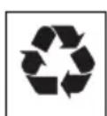
| Dimensions (W x D) | 596 x 340 mm |
| Estimated net weight | 8 kg |
| Power supply | 220-240 V ~ 50 Hz |
| Number of speeds | 3 + turbo mode |
| Control type | Mechanical (push buttons) |
| Exhaust mode | Ducted or recirculating (charcoal filter optional) |
| Grease filter | Aluminium, dishwasher safe, clean every 35 hours |
| Charcoal filter | Optional, replace every 6 months |
| Lighting | 1 GU10 bulb (not provided) |
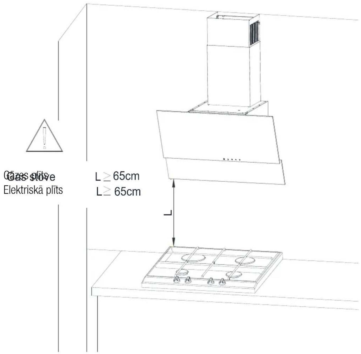
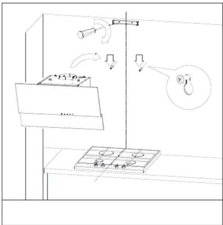
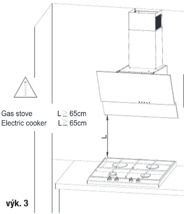
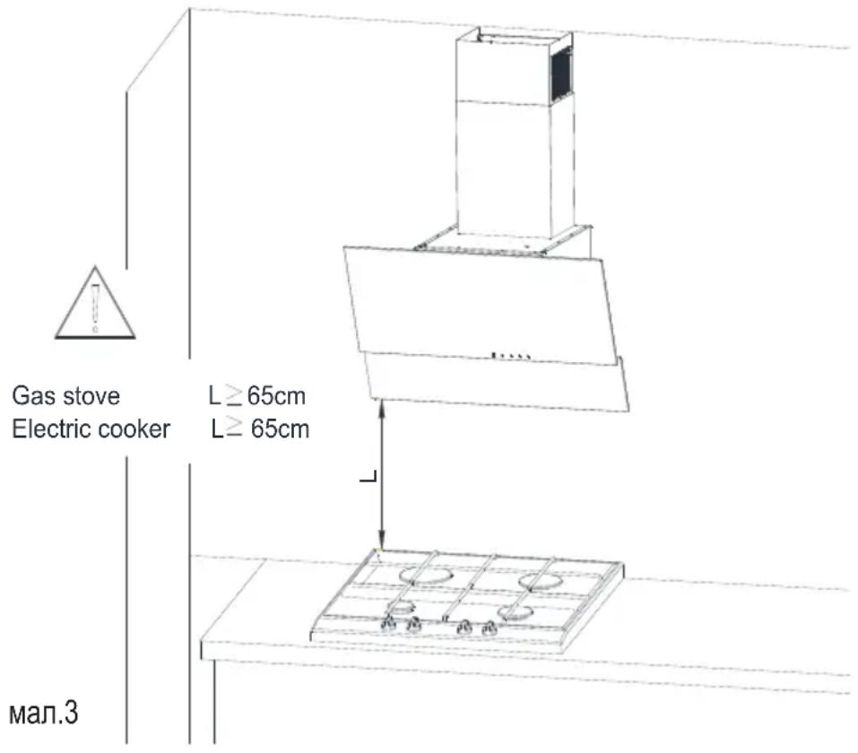
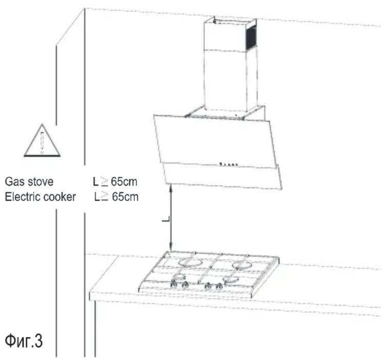
| Minimum installation distance | 65 cm between hood and hob |
| Material | Stainless steel |
| Special functions | Auto shut-off timer (15 min), turbo mode (5 min), touch lock |
| Spare parts available | Filters, bulb |
Frequently Asked Questions - HCA62320WH BEKO
User questions about HCA62320WH BEKO
0 question about this device. Answer the ones you know or ask your own.
Ask a new question about this device
Download the instructions for your Basket in PDF format for free! Find your manual HCA62320WH - BEKO and take your electronic device back in hand. On this page are published all the documents necessary for the use of your device. HCA62320WH by BEKO.
USER MANUAL HCA62320WH BEKO
natural_image
Simple line icon of a chimney emitting steam (no text or symbols)HCA62320W
HCA62320B
HCA62320WH
HCA62320BH
EN-PL-RO-DE-ES-FR-NL-CS-SL-SK-UA-BG-RU-ET-LT-LV
Please read this user manual first!
Dear Valued Customer,
Thank you for preferring this Beko appliance. We hope that you get the best results from your appliance which has been manufactured with high quality and state-of-the-art technology. For this reason, please read this entire user manual and all other accompanying documents carefully before using the appliance and keep it as a reference for future use. If you handover the appliance to someone else, give the user manual as well. Follow the instructions by paying attention to all the information and warnings in the user manual.
Remember that this user manual may also apply to other models. Differences between models are explicitly described in the manual.
Meanings of the Symbols
Following symbols are used in various sections of this user manual:

Important information and useful hints about usage.

WARNING: Warnings against dangerous situations concerning the security of life and property.
Warning for danger of fire.
Warning for electric shock.

Protection class against electric shock.

This appliance has been manufactured in environmentally friendly modern plants without giving any harm to the nature.
CONTENTS
ENGLISH 04-15
POLSKI 16-33
ROMÂNĂ 34-50
DEUTSCH 51-67
ESPAÑOL 68-84
FRANÇAIS 85-100
NEDERLANDS 101-116
ČESKY 117-132
SLOVENŠČINA 133-147
SLOVENSKÝ 148-163
УКРАЇНСЬКИЙ 164-181
български 182-199
RUSSIAN 200-218
EESTI 219-231
LIETUVIŲ K 232-244
LATVIA 245-258
1 Important Safety and Environmental Instructions
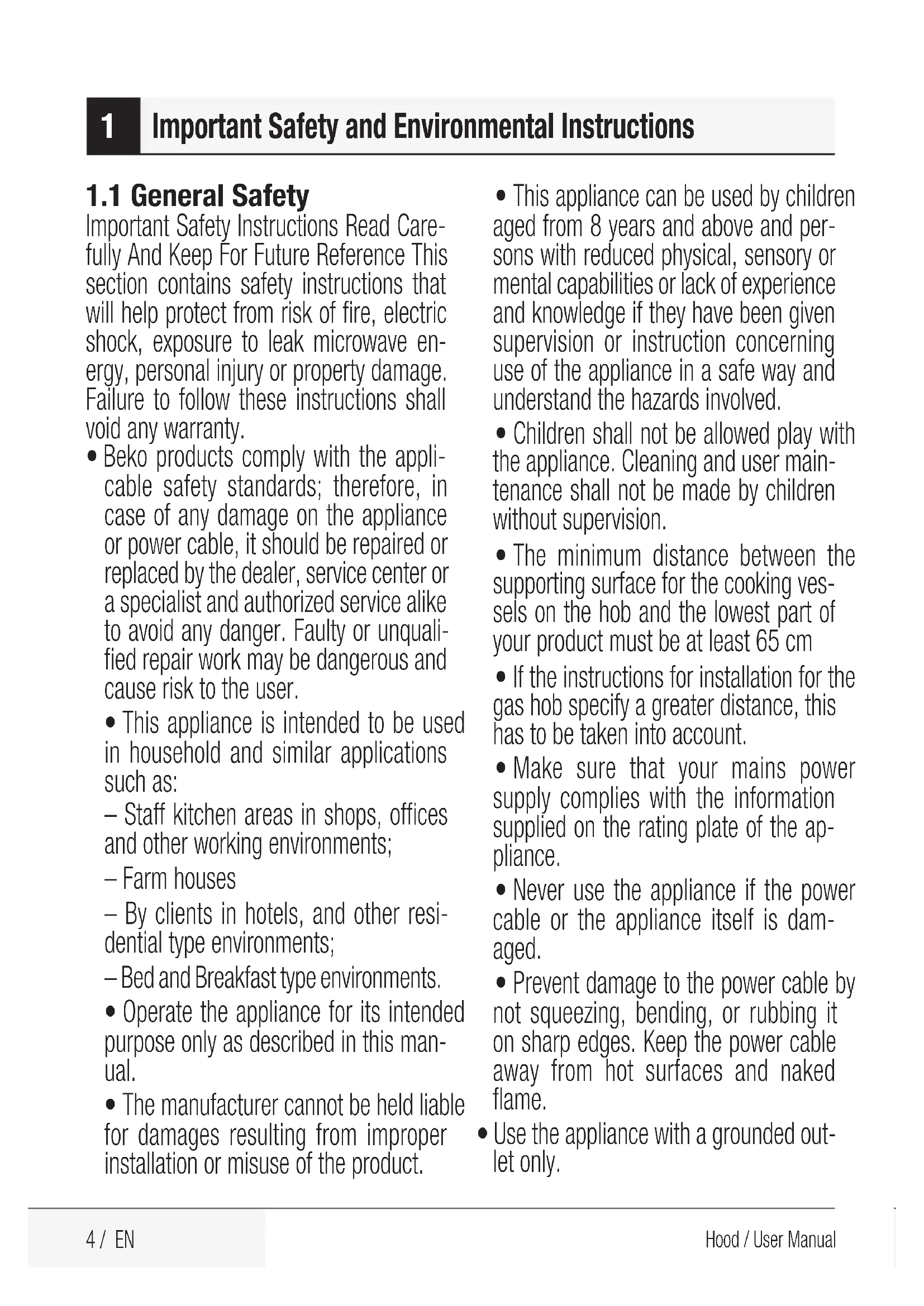
1.1 General Safety
Important Safety Instructions Read Carefully And Keep For Future Reference This section contains safety instructions that will help protect from risk of fire, electric shock, exposure to leak microwave energy, personal injury or property damage. Failure to follow these instructions shall void any warranty.
- Beko products comply with the applicable safety standards; therefore, in case of any damage on the appliance or power cable, it should be repaired or replaced by the dealer, service center or a specialist and authorized service alike to avoid any danger. Faulty or unqualified repair work may be dangerous and cause risk to the user.
- This appliance is intended to be used in household and similar applications such as:
- Staff kitchen areas in shops, offices and other working environments;
- Farm houses
- By clients in hotels, and other residential type environments;
- Bed and Breakfast type environments.
- Operate the appliance for its intended purpose only as described in this manual.
- The manufacturer cannot be held liable for damages resulting from improper installation or misuse of the product.
- This appliance can be used by children aged from 8 years and above and persons with reduced physical, sensory or mental capabilities or lack of experience and knowledge if they have been given supervision or instruction concerning use of the appliance in a safe way and understand the hazards involved.
- Children shall not be allowed play with the appliance. Cleaning and user maintenance shall not be made by children without supervision.
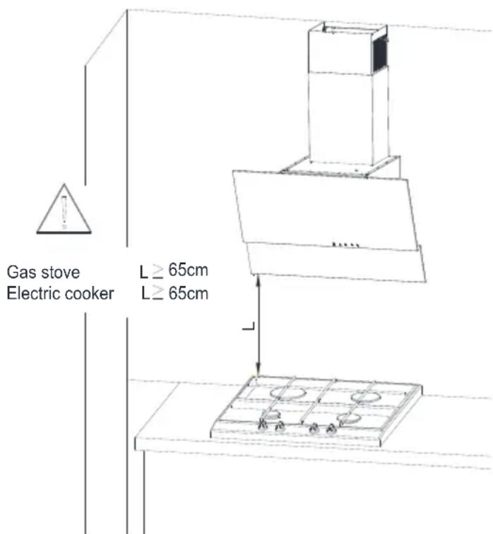
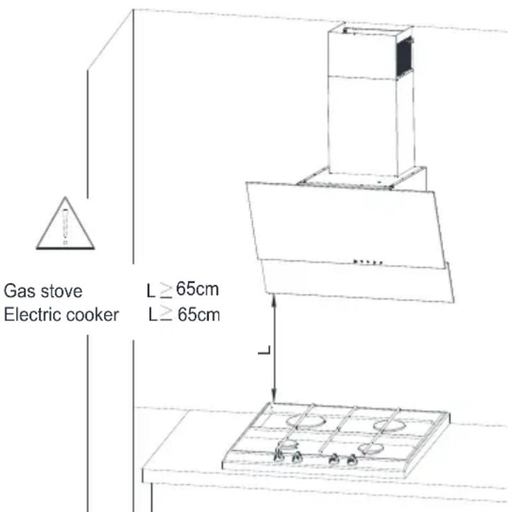
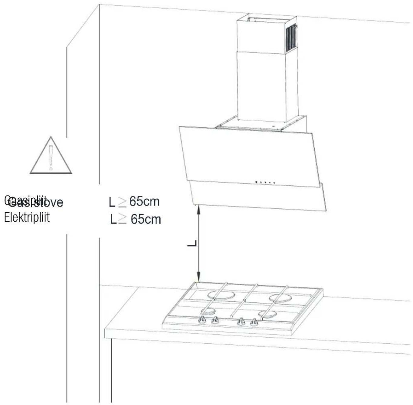
- The minimum distance between the supporting surface for the cooking vessels on the hob and the lowest part of your product must be at least 65 cm
- If the instructions for installation for the gas hob specify a greater distance, this has to be taken into account.
- Make sure that your mains power supply complies with the information supplied on the rating plate of the appliance.
- Never use the appliance if the power cable or the appliance itself is damaged.
- Prevent damage to the power cable by not squeezing, bending, or rubbing it on sharp edges. Keep the power cable away from hot surfaces and naked flame.
- Use the appliance with a grounded outlet only.
1 Important Safety and Environmental Instructions
WARNING: Do not connect the appliance to the mains until the installation is fully complete.
- Place the appliance in a way so that the plug is always accessible.
- Do not touch the lamps if they have operated for a long time. They can burn your hands since they will be hot.
- Follow the regulations set out by competent authorities on discharge of the exhaust air (this warning is not applicable for use without flue).
- Operate your appliance after putting a pot, pan etc. on the hob. Otherwise, high heat may cause deformation in some parts of your product.
- Turn off the hob before taking the pot, pan etc. from it.
- Do not leave hot oil on the hob. Pans with hot oil may cause self combustion.
- Pay attention to your curtains and covers since oil may catch fire while cooking food such as fries.
- Grease filter must be replaced at least monthly. Carbon filter must be replaced at least every 3 months.
- Product shall be cleaned accordance with user manual. If cleaning was not carried out in accordance with user manual, there may be fire risk.
- Do not use non-fire-resistant filtering materials instead of the current filter.
- Only use the original parts or parts rec-
ommended by the manufacturer.
- Do not operate the product without the filter and do not remove the filters while the product is running.
- In the event of be started any flame, de-energize your product and cooking appliances.
- In the event of be started any flame, cover the flame and never use water to extinguish.
- Unplug the appliance before each cleaning and when the appliance is not in use.
- The negative pressure in the environment should not exceed 4 Pa (4 x 10 bar) while the hood for electric hob and appliances running on another type of energy but electricity operate simultaneously.
- In the environment where the appliance is being used, the exhaust of devices running on fuel oil or gas, such as room heater must be absolutely isolated or device must be hermetical type.
- When connecting the flue, use pipes with a diameter of 120 or 150mm . Pipe connection must be as short as possible and have as few elbows as possible.
Danger of choking! Keep all the packaging materials away from children.
CAUTION: Accessible parts may become hot when used with cooking ap-
1 Important Safety and Environmental Instructions
pliances.
- The product outlet must not be connected to air channels that include other smoke.
- The ventilation in the room may be insufficient when the hood for electric hob is used simultaneously with the devices operating on gas or other fuels (this may not apply to appliances that only discharge the air back into the room).
- Objects placed on the product may fall. Do not place any objects on the product.
- Do not flambe under the your product.
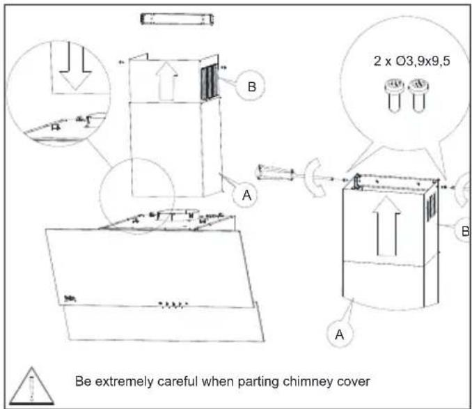
WARNING: Before installing the Hood, remove the protective films.
- Never leave high naked flames under the hood when it is in operation
- Deep fat fryers must be continuously monitored during use: overheated oil can burst into flames.
1.2 Compliance with the WEEE Directive and Disposing of the Waste Product:
This product complies with EU WEEE Directive (2012/19/EU). This product bears a classification symbol for waste electrical and electronic equipment (WEEE).
This symbol indicates that this product shall not be disposed with other household wastes at
the end of its service life. Used device must be returned to official collection point for recycling of electrical and electronic devices. To find these collection systems please contact to your local authorities or retailer where the product was purchased. Each household performs important role
in recovering and recycling of old appli- ance. Appropriate disposal of used ap- pliance helps prevent potential negative consequences for the environment and human health.
1.3 Compliance with RoHS Directive
The product you have purchased complies with EU RoHS Directive (2011/65/EU). It does not contain harmful and prohibited materials specified in the Directive.
1.4 Package Information
Packaging materials of the product are manufactured from recyclable materials in accordance with our National Environment Regulations. Do not dispose of the packaging materials together with the domestic or other wastes. Take them to the packaging material collection points designated by the local authorities.
2 General Appearance
2.1 Overview
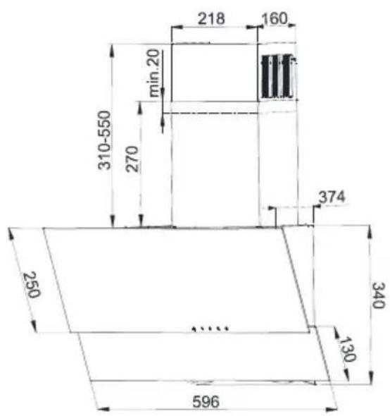
Fig. 1
- Chimney
- Body
- Aluminum Grease Filter
- Hob Lighting
- Control Panel
- Power Supply Cord
- Carbon Filter
(HCA62320WH - HCA62320BH)
2.2 Technical Data
| Model HCA62320W HCA62320B HCA62330WH HCA62320BH | |||
| Supply Voltage and Frequency | 220-240 V 50 Hz | ||
| Lamp Power (W) | 2 x3 | ||
| Motor Power (W) | 115 | ||
| Air Flow (m3/h) – 3. Level 305 | |||
| Motor Insulation Class Class F | |||
| Insulation Class Class II | |||
3 Using the Appliance
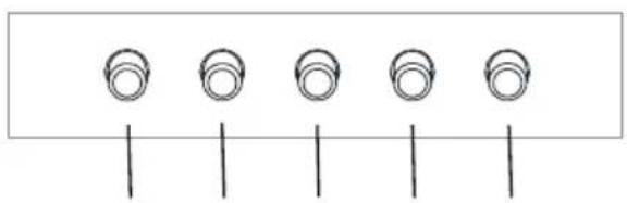
3.1 Use of the Rocker Switch
natural_image
Simple line drawing of five circular components aligned horizontally with vertical lines (no text or symbols)Fig. 3 1230
The hood is equipped with a mechanical control.
- Pressing the "0" - disables the hood.
- Pressing the "1" - to turn the hood with a minimum speed.
- Pressing the "2" - turns the hood with an average speed.
- Pressing the "3" - turns the hood at maximum speed.
Higher speed means more air flow.
- Press the button to turn on the lights. Repeat pressing the button to turn off the lighting.
3.2 Things to Do for Energy Saving
- Ensure sufficient air intake to make the hood operate efficiently and with low operation noise during cooking.
- Set the fan level according to the density of steam in kitchen. Use the high level only when needed. A lower fan level means less energy consumption.
- If dense smoke is expected in the kitchen, select a higher level of fan in advance. It is required to operate the hood much longer to remove the smoke already spread all over kitchen.
- Turn off the hood when not in use.
- Clean or replace the filter at intervals stated, thus, the efficiency of the ventilation is increased and the risk of fire is eliminated.
3.3 Operating the Hood
- Hood is equipped with a motor having various speed settings.
- For a better performance, we advise you to use low speeds in normal conditions, and high speeds when smell and vapors are intensified.
- You can start the hood by pressing the desired speed level key.(1,2,3)
- You can illuminate the cooking area by pressing the light key. (- ∫)
3.4 Lamp Replacement
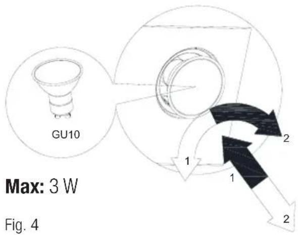
Symbol → Bulb installation Symbol → Bulb dismantling
Disconnect the hood from the mains supply. This appliance is equipped with 3 W spot LED lamps.
Before replacing the light bulbs, disconnect the power supply of the hood.

Do not touch the light bulbs when they are hot.

Be careful not to touch the replaced light bulb directly with hands.

You may procure lamps from Authorised Service Agents.
4 Cleaning and Maintenance
Prior to cleaning and maintenance, unplug the appliance or turn the main switch off or loosen the fuse that supplies the hood.
Failure to comply with the provisions relating to cleaning of the device and replacement of filters may cause fire risks. It is therefore recommended to comply with the guidelines given herein. The manufacturer is not liable for any damage to the engine or fires caused by improper use.
Clean using only a cloth dampened with neutral liquid detergent. Do not clean with tools or instruments. Do not use abrasive products. Do not use alcohol
4.1 Cleaning of Aluminium Grease Filter
This filter captures oil particles in the air. You are recommended to clean your filter every month under normal usage conditions. First remove the grease filters for this process. Wash the filters with liquid detergent and rinse them with water and install them back after they get dry. Aluminium grease filters may get discolored as they are washed; this is normal and you don't need to change your filter.
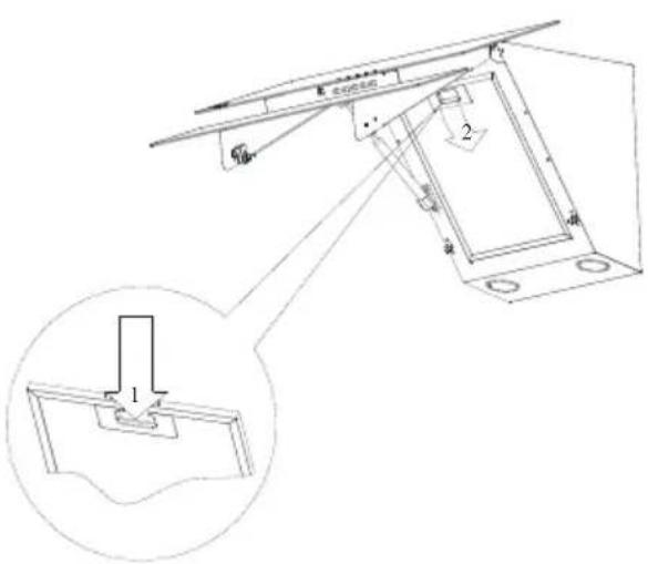
Fig. 5

You can wash the grease filter in the dishwasher
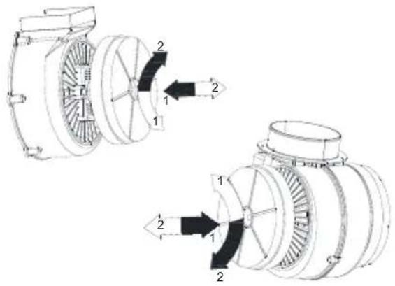
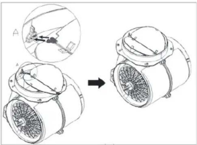
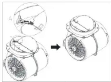
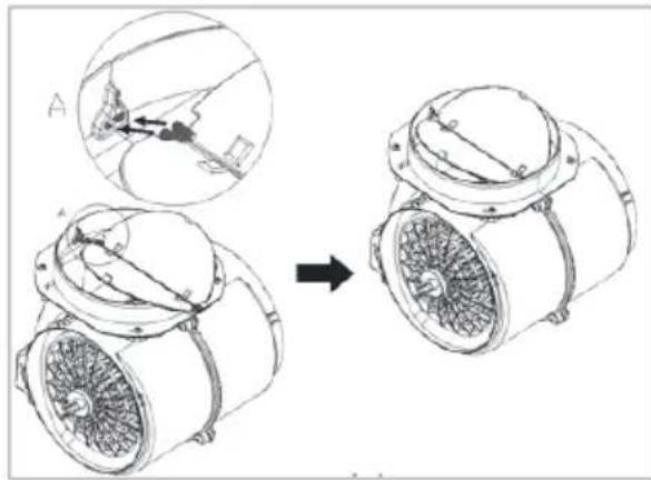
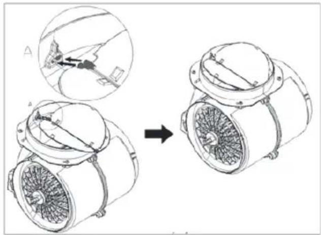
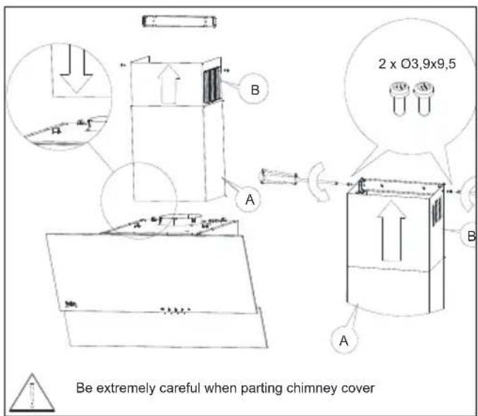
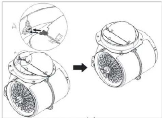
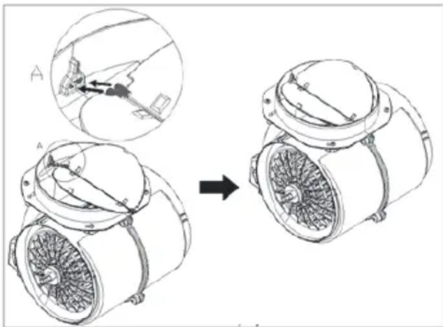
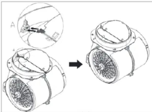
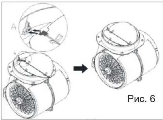
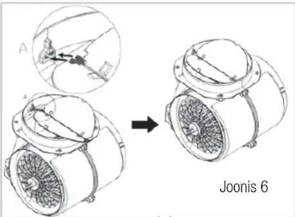
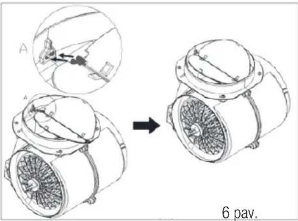
4.2 Changing of Carbon Filter (Air Circulation Mode)
The hood can be fitted with an active carbon filter. The carbon filter is applied only in case the hood is not connected to the vent duct.
In any case it is necessary to replace the carbon filter at least every three months.

natural_image
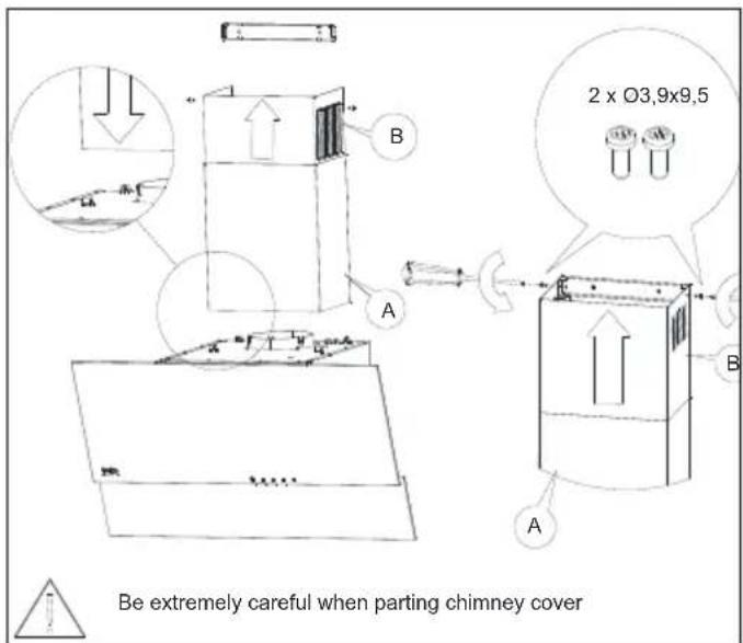
Technical illustration of a mechanical device showing a disassembly process with labeled components (no text or symbols present)
WARNING: The carbon filter is never washed.

WARNING: Carbon filter is available from Authorized Services.
5 Setting Up the Device
WARNING
Please read safety instructions before setting up.
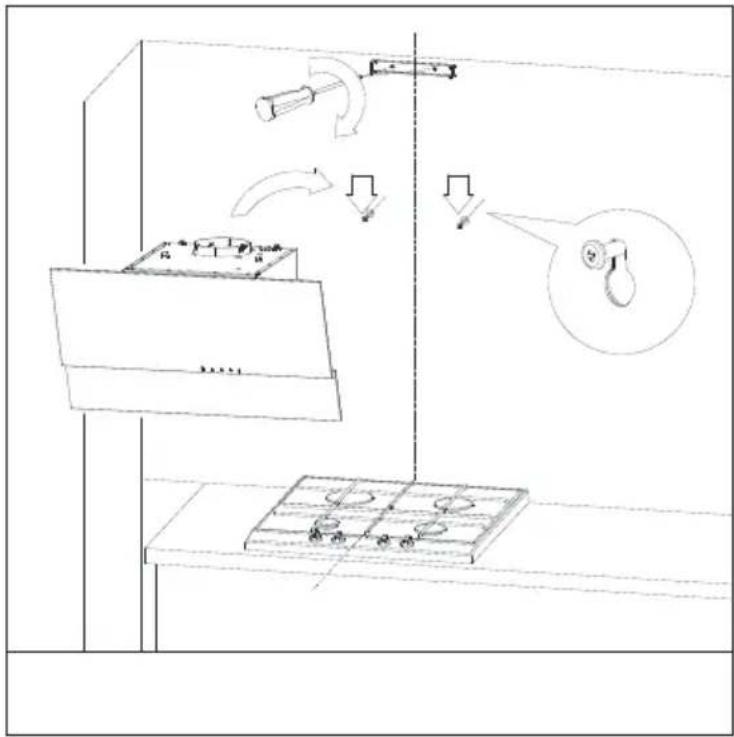
WARNING
Failure to install the screws or fixing device in accordance with these instructions may result in electrical hazards.
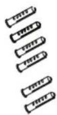
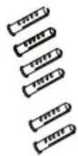
5.1 Installation Accessories
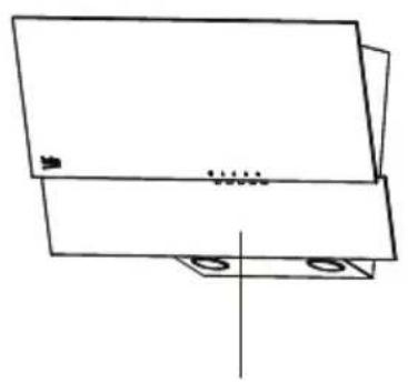
natural_image
Simple line drawing of a rectangular object with two mounting holes and a vertical line (no text or symbols)1

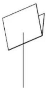
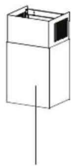
natural_image
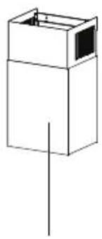
Simple line drawing of a box with a vertical line and a small inset box, no text or symbols present.2
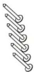
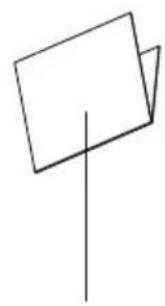
natural_image
Simple line drawing of two overlapping rectangles with a vertical line (no text or symbols)3
4

5
Fig. 7
1- Hood
2- Chimney
3- User Manual
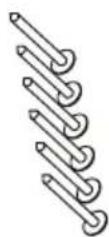
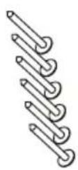
4- 6x ∅4,0x45 Screw
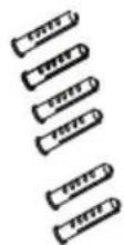
5- 6x ∅8x40 Screw Plug
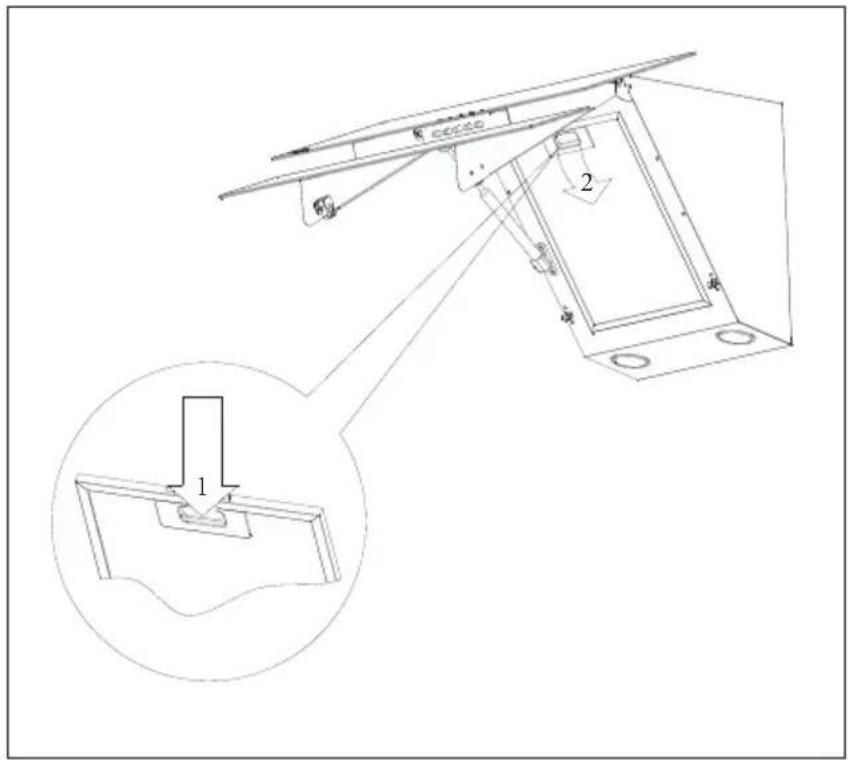
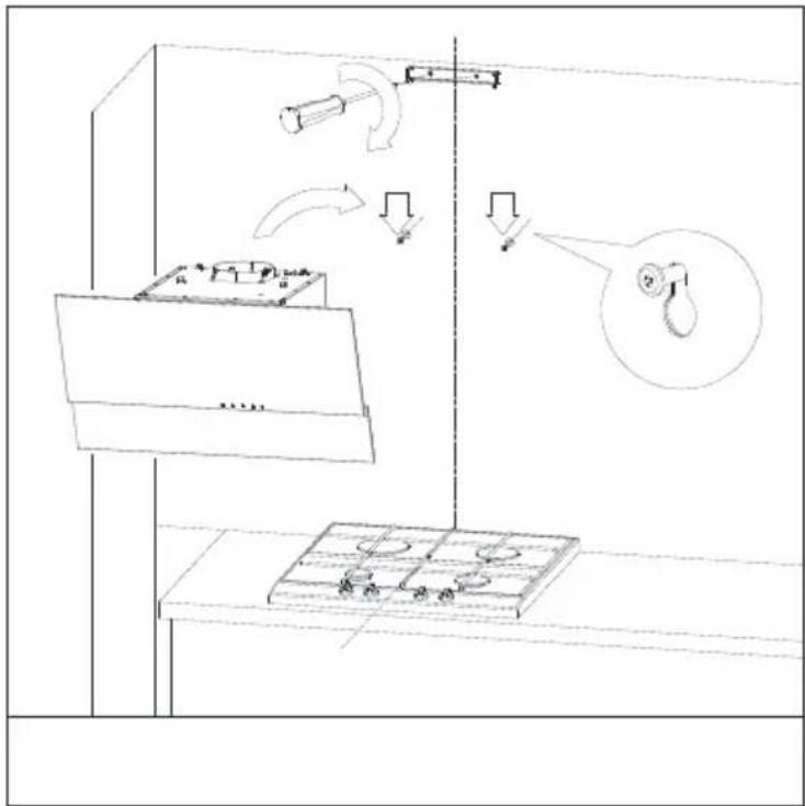
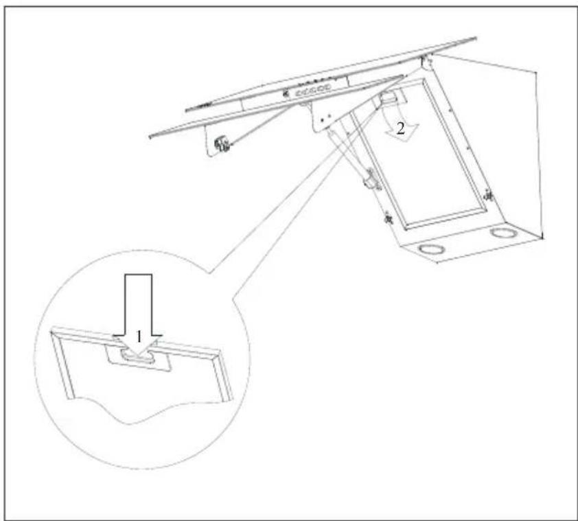
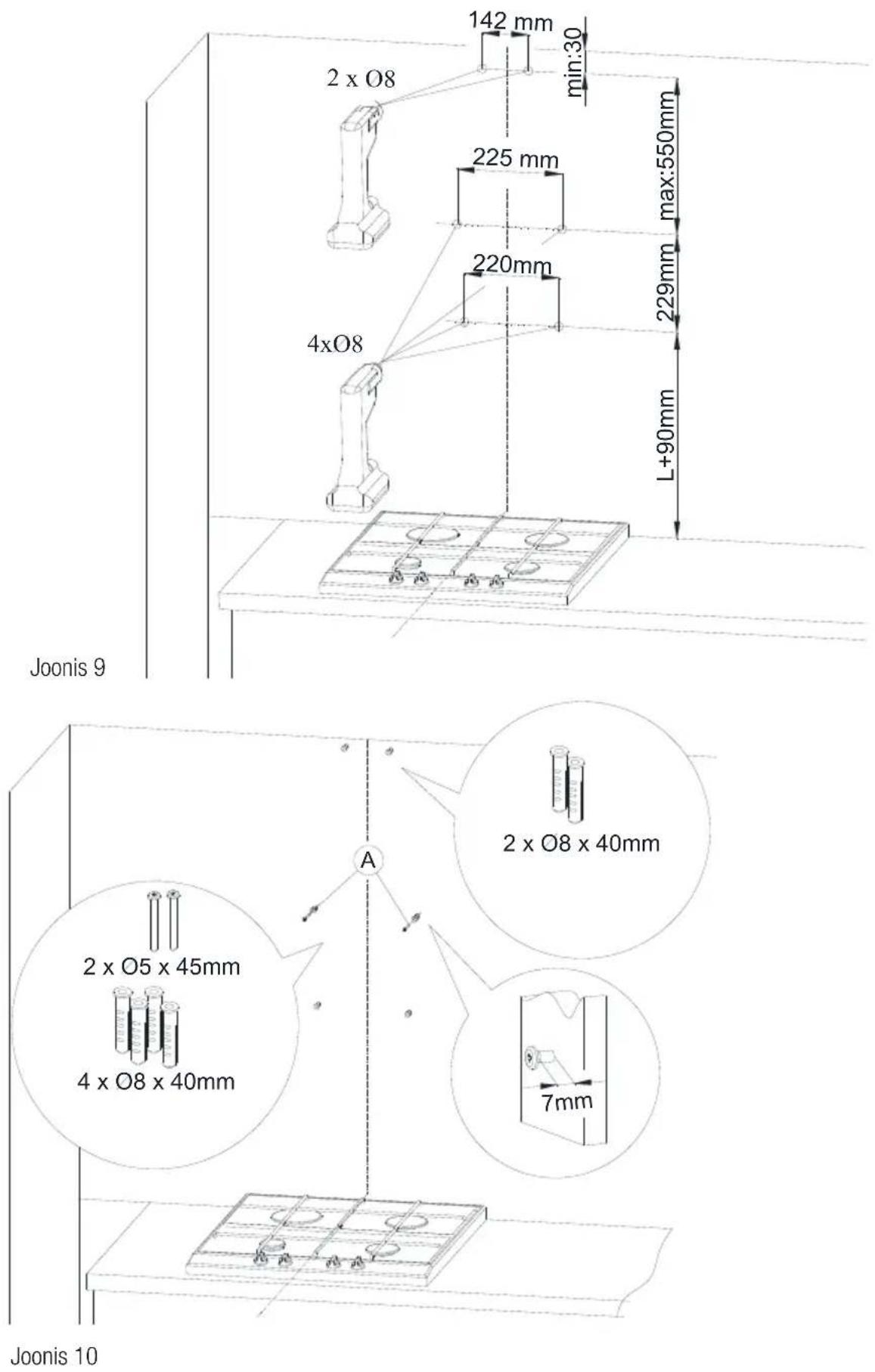
5 Setting Up the Device
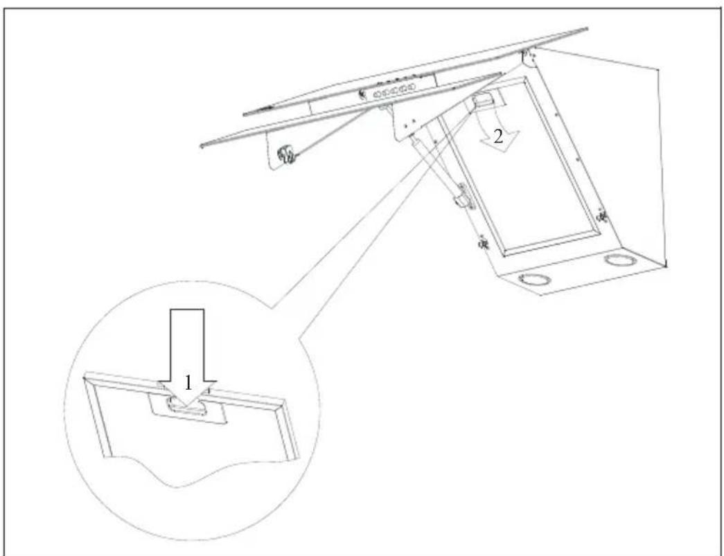
5.2 Installation of the Device
Suggested distance from the kitchen cooker.
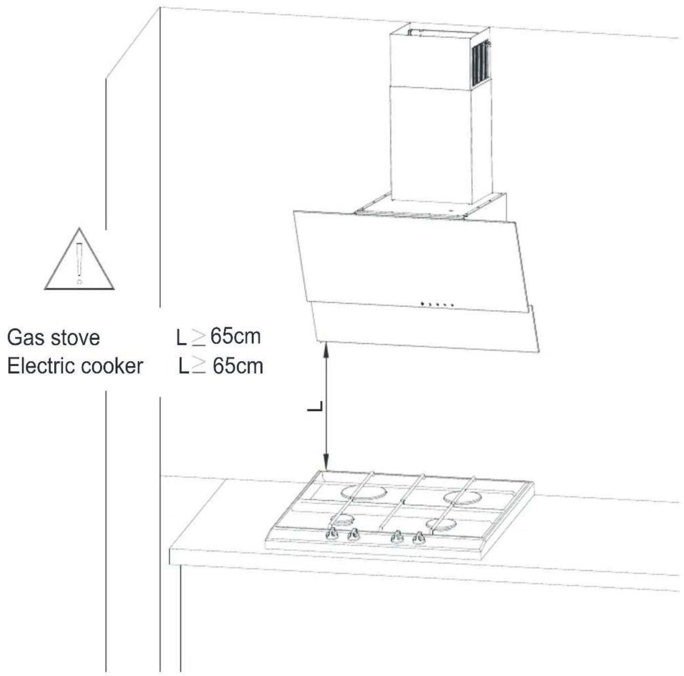
Fig. 8
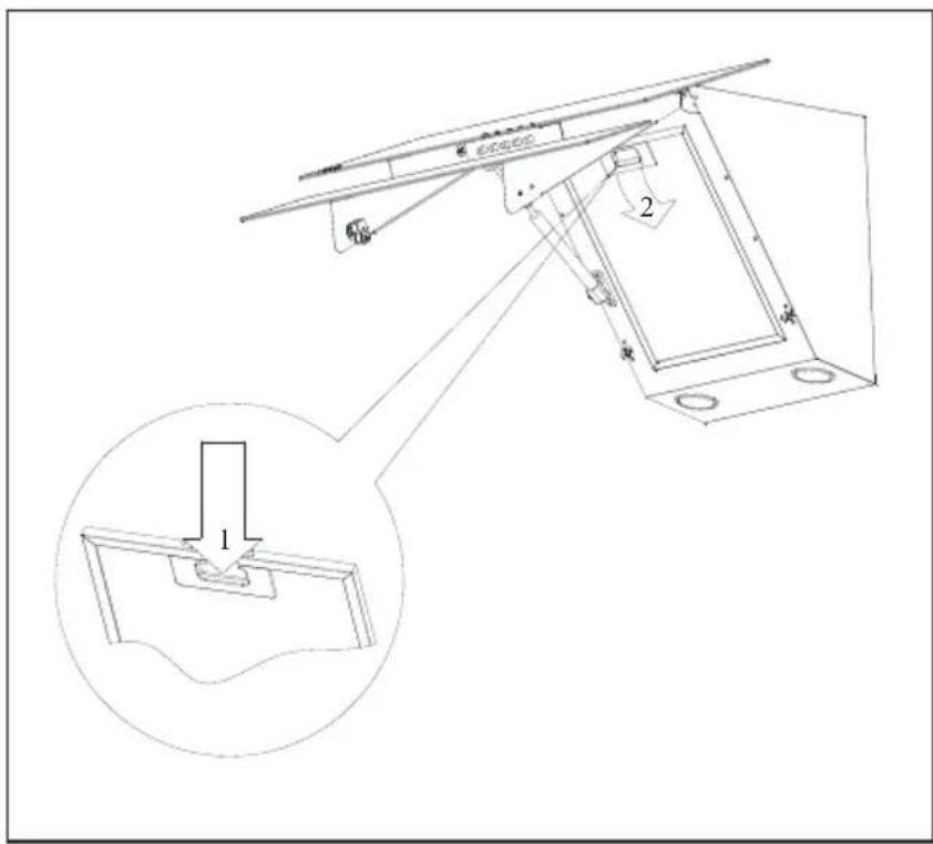
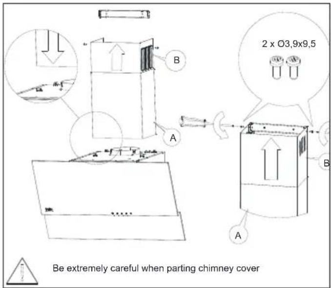
5 Setting Up the Device
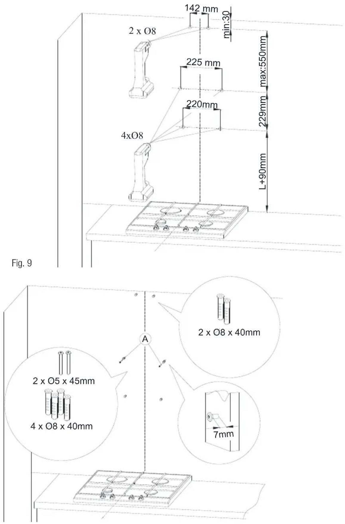
Fig. 10
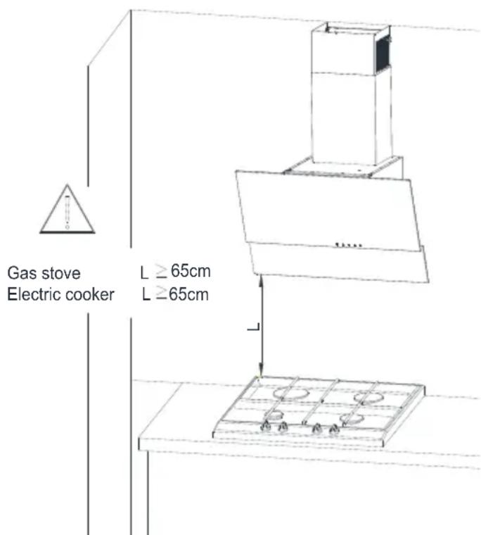
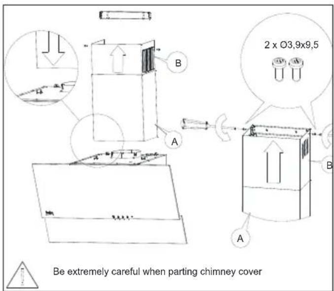
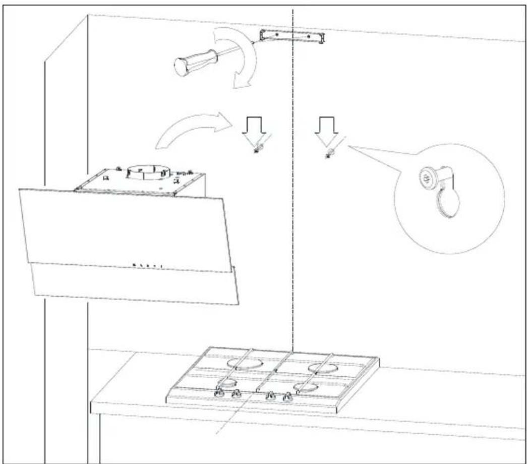
5 Setting Up the Device
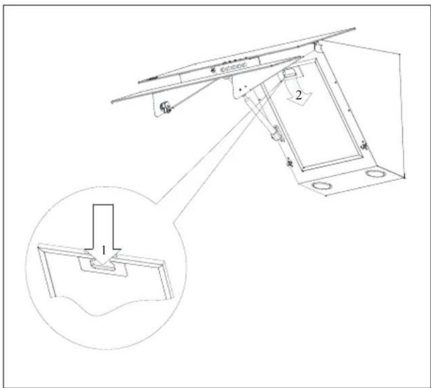
Fig. 11

Fig. 12

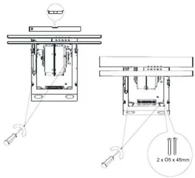
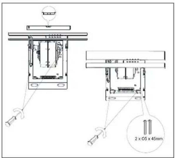
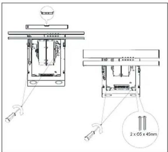
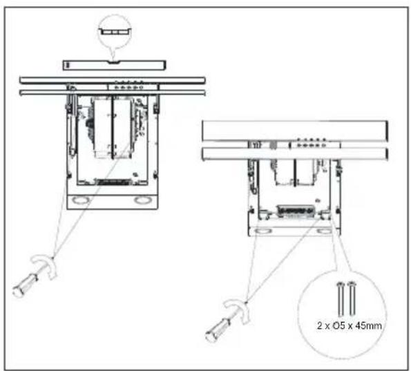
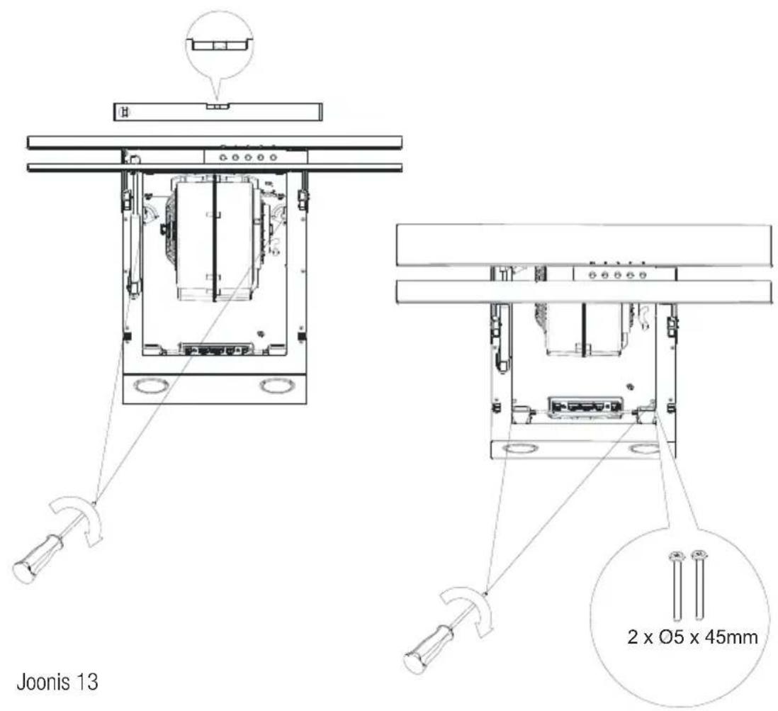
5 Setting Up the Device

2 x 05 x 45mm
Fig. 14

6 Troubleshooting
| Troubleshooting Root Cause Help | ||
| Appliance is not working. | Check your fuses. Fuse may be blown, inspect | and restore it. |
| Appliance is not working. | Check the electrical connection. Mains voltage shall be between 220 and 240 V. | |
| Appliance is not working. | Check the electrical connection. | Check if other appliance in your kitchen operate. |
| Illumination light does not operate. | Check the electrical connection. Mains voltage shall be between 220 and 240 V. | |
| Illumination light does not operate. | Inspect the lamp switch. Lamp switch shall be at "on" position. | - |
| Illumination light does not operate. | Inspect the lamps. The lamps of the appliance shall illuminate. | - |
| Air inlet of the appliance is inadequate. | Inspect the aluminium filter. Under normal operating conditions, aluminium grease filter shall be cleaned at least once in a month. | |
| Air inlet of the appliance is inadequate. | Check the air discharge chimney. The air discharge chimney shall be at "on" position. | |
| Air inlet of the appliance is inadequate. | Inspect the carbon filter. The filters of the appliances with carbon filters shall be replaced once in every 3 months under normal conditions. | |
Suggested distance from the kitchen cooker.
Rys. 3
4 Montaż okapu
Rys. 6
Rys. 7
4 Montaż okapu
Rys. 8
Rys. 9
natural_image
Technical line drawing of a mechanical assembly showing two stages of assembly, with no visible text or symbols.Rys. 10
Rys. 11
Suggested distance from the kitchen cooker.
Sch. 3
Sch.7
Sch. 9
natural_image
Diagram showing two views of a fan or fan assembly with internal components, no text or symbols presentSch. 10
6 Comanda de functionare a hotei
6.1 Comanda hotei
Suggested distance from the kitchen cooker.
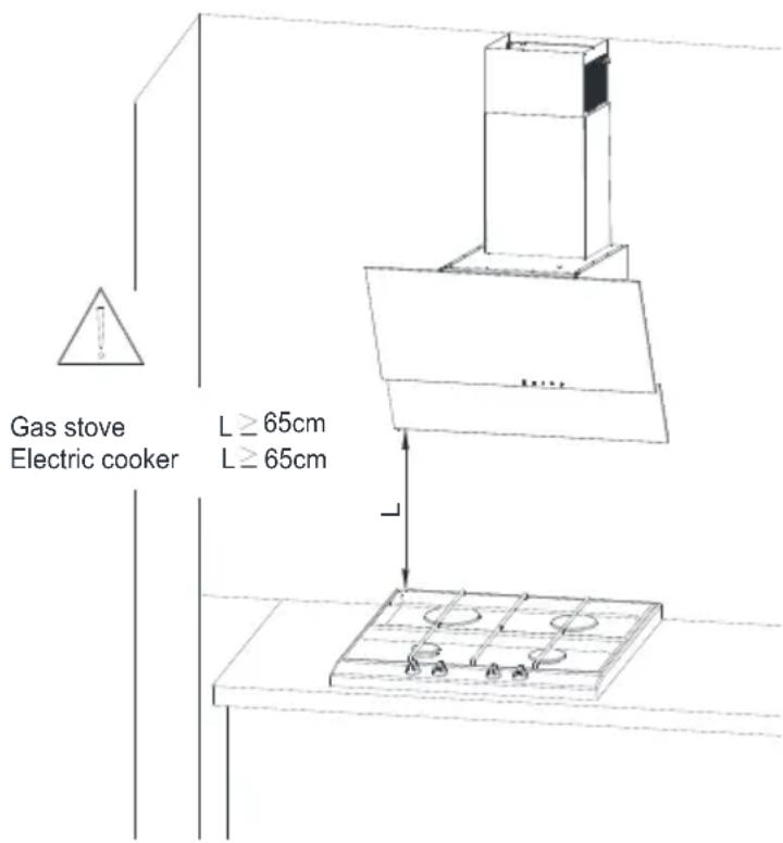
Abb. 3
Abb.7
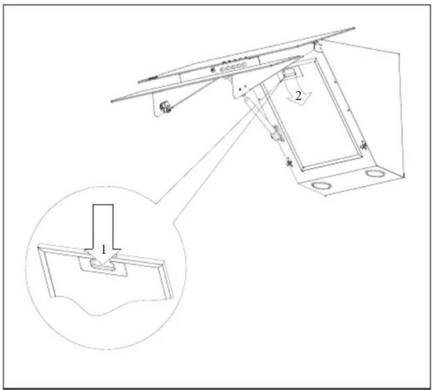
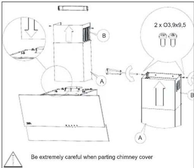
Abb. 9
natural_image
Technical line drawing of a mechanical component before and after assembly, showing internal structure and motion (no text or symbols)Abb. 10
Suggested distance from the kitchen cooker.
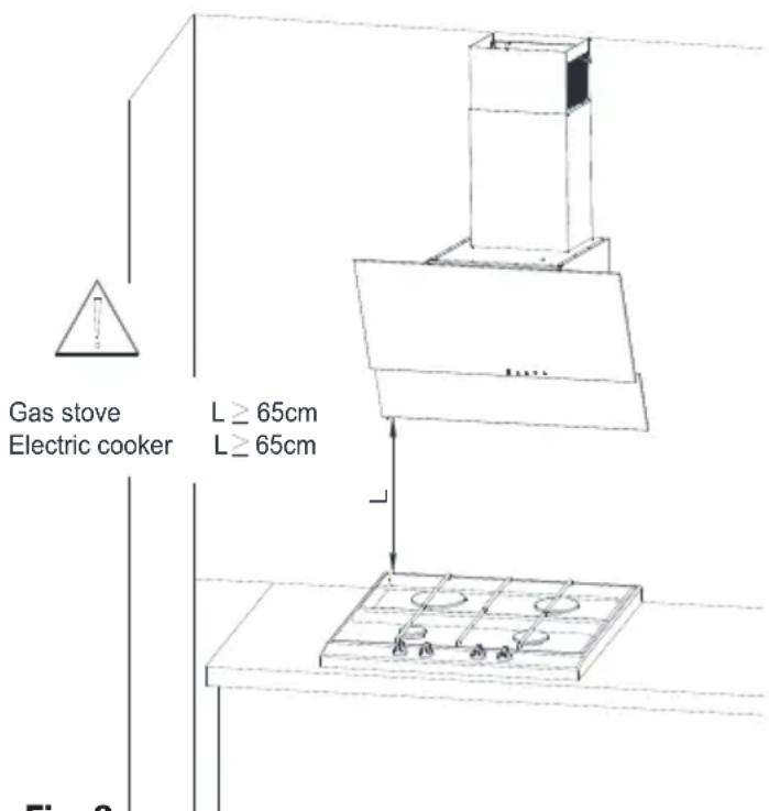
Fig. 3
Fig.7

Fig. 9

natural_image
Technical illustration of a mechanical assembly showing a disassembled fan component before and after assembly (no text or symbols present)Fig. 10
Suggested distance from the kitchen cooker.
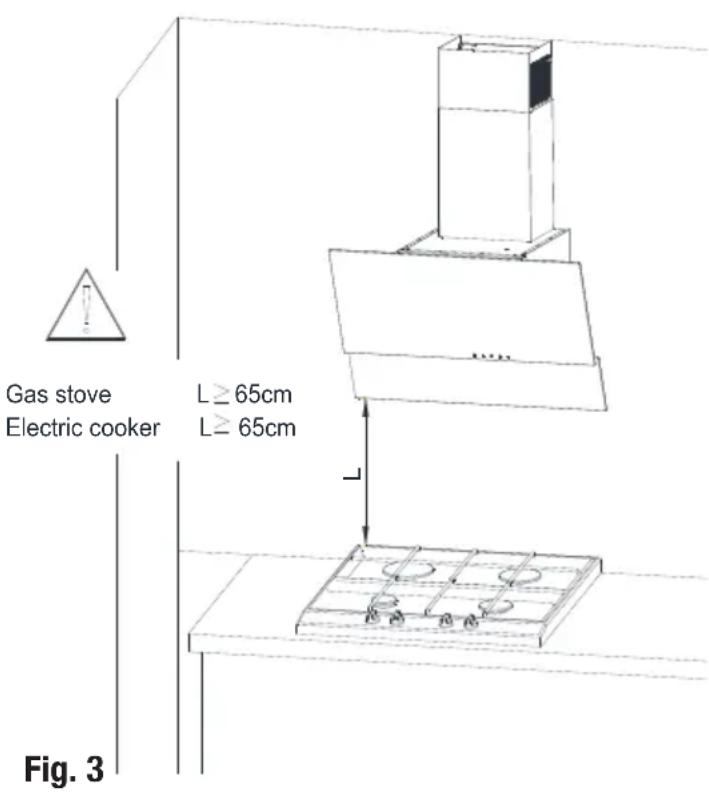
Fig.7

Fig. 9

natural_image
Technical line drawing of a mechanical component before and after assembly, showing internal components and motion direction (no text or symbols). 10
Suggested distance from the kitchen cooker.
afb. 3
4 Uw apparaat installeren
afb.6
afb.7

4 Uw apparaat installeren
afb. 8
afb. 9


natural_image
Technical line drawing of a mechanical assembly showing two stages of assembly, with no visible text or symbols.afb. 10
Suggested distance from the kitchen cooker.
výk.7
výk. 9
natural_image
Technical line drawing of a mechanical device showing assembly and disassembly (no text or symbols)výk. 10
5 Čištění a údržba
Suggested distance from the kitchen cooker.
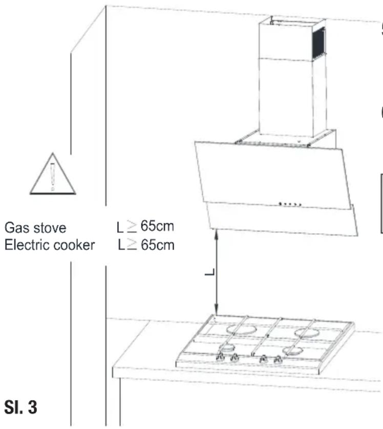
SI.7

SI. 9

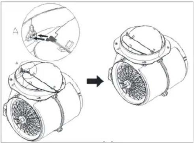
natural_image
Technical illustration of a mechanical fan assembly showing internal components before and after assembly (no text or symbols)Sl. 10
6 Upravljanje delovanja nape
6.1 Upravljanje nape
Napa je opremljena z mehanskim upravljanjem.
Suggested distance from the kitchen cooker.
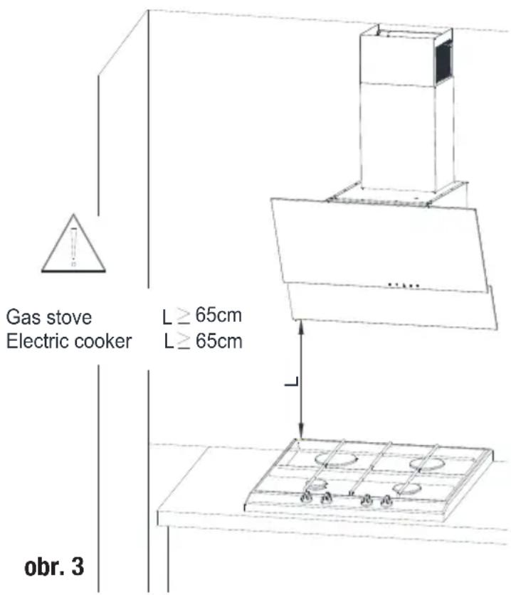
obr.7

obr. 9
natural_image
Technical line drawing of a mechanical fan assembly before and after assembly (no text or symbols)obr. 10
5 Čistenie a údržba
Suggested distance from the kitchen cooker.
4 Установка приладу
4 Установка приладу
мал.6
мал.7

4 Установка приладу
мал.8
мал.9

natural_image
Technical illustration of a mechanical fan assembly showing internal components before and after assembly (no text or symbols)Мал. 10
Suggested distance from the kitchen cooker.
4.1 Монтаж
4 Монтаж на уреда
Фиг.6

Фиг.7
4 Монтаж на уреда
Фиг.8
Фиг.9
natural_image
Technical line drawing of a mechanical fan assembly showing internal components before and after assembly (no text or symbols)Фиг.10
natural_image
Simple line icon of a chimney emitting steam (no text or symbols)HCA62320W
HCA62320B
HCA62320WH
HCA62320BH
RU
natural_image
Two identical 3D mechanical rings with central holes, connected by a horizontal line (no text or symbols)natural_image
Simple diagram of five identical circular components aligned horizontally with vertical lines (no text or symbols)Рис. 3 1230
natural_image
Technical illustration of a mechanical component before and after assembly, showing internal structure and assembly (no text or symbols)
natural_image
Simple line drawing of a rectangular object with two circular base points and a small mark on top (no text or symbols)1
natural_image
Simple line drawing of a box with a vertical line and a small inset box, no text or symbols present.2
ВНИМАНИЕ
natural_image
Simple line drawing of two overlapping rectangles with a vertical line (no text or symbols)3

Рис. 7
4
5
Рис. 12
natural_image
Pure electrical circuit lines without any symbolsJoonis 3

1230
Joonis 5

Rasvafiltreid saab pesta nõudepesumasinas.

HOIATUS: Söefiltrit ei tohi kunagi pesta.
HOIATUS: Söefilter on saadaval volitatud teenindustes.
5 Seadme sätestamine

HOIATUS
natural_image
Simple line drawing of a rectangular object with two circular holes and a vertical axis (no text or symbols)1

natural_image
Simple line drawing of a box with a vertical line and a small inset box, no text or symbols present.2

natural_image
Simple line drawing of two overlapping rectangles with a vertical line (no text or symbols)3
Joonis 7
4
5
1-1Õhupu hasti
2- Korsten
3- Kasutusjuhend
4- 6x 04,0 x 45 kruvi
5- 6x 08 x 40 kruvikork
5 Seadme sätestamine
5.2 Seadme paigaldamine
Sogvitatav kaugus köögipliidist Suggested kaisuncen in the kitchen cooker.
Joonis 8
5 Seadme sätestamine
5 Seadme sätestamine
Joonis 11
Joonis 12

5 Seadme sätestamine
Joonis 14
6 Törkeotsing
5 pav.


JSPÈJIMAS: Anglies filtro plauti negalima.

natural_image
Simple line drawing of a rectangular object with two circular holes and a vertical axis (no text or symbols)1
natural_image
Simple line drawing of a rectangular box with a vertical line extending from its top (no text or symbols)2
natural_image
Simple line drawing of two overlapping rectangles with a vertical line (no text or symbols)3
7 pav.
4
5

natural_image
Pure diagram of five identical circular components aligned horizontally with vertical lines below (no text or symbols)- att.

1230
- att.


natural_image
Simple line drawing of a rectangular object with two mounting holes and a vertical axis (no text or symbols)1

natural_image
Simple line drawing of a box with a vertical line and a small inset box (no text or symbols)2

natural_image
Simple line drawing of two overlapping rectangles with a vertical line (no text or symbols)3

7. att.
4
5
leteqamais attalums nor virtuvs pits suggested distance from the kitchen cooker.