
T1600G28TS - Switch TP-LINK - Free user manual and instructions
Find the device manual for free T1600G28TS TP-LINK in PDF.
| Product type | Network switch |
| Brand | TP-Link |
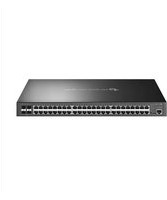
| Model | T1600G28TS |
| Number of ports | 24 Gigabit Ethernet RJ45 ports + 4 SFP slots |
| Power supply | 100-240 V AC, 50/60 Hz |
| Power consumption | Max 20.16 W |
| Dimensions (L x D x H) | 440 x 180 x 44 mm |
| Weight | 2.5 kg |
| Operating temperature | 0 °C to 40 °C |
| Operating humidity | 10 % to 90 % RH non-condensing |
| Installation | Desktop or 19-inch rack |
| Management interface | Web (HTTP/HTTPS), CLI (console), SNMP |
| Supported protocols | IEEE 802.3, 802.3u, 802.3ab, 802.3x, 802.1Q, 802.1p |
| Security features | VLAN (802.1Q), ACL, IGMP Snooping, DHCP Snooping |
| QoS functions | Port priority, 802.1p, DSCP |
| Advanced features | Link aggregation (LACP), Spanning Tree (STP/RSTP/MSTP), Port mirroring |
| LED indicators | Power, link/activity per port, speed |
| Package contents | Switch, power cord, rack mounting kit, rubber feet, quick installation guide |
| Maintenance and cleaning | Unplug the device and use a soft dry cloth. Do not use chemical or abrasive cleaners. |
| Warranty | TP-Link limited warranty (see manual for exact duration) |
| Repairability | Do not disassemble the device. For any repairs, contact TP-Link customer service or an authorized center. |
Frequently Asked Questions - T1600G28TS TP-LINK
User questions about T1600G28TS TP-LINK
0 question about this device. Answer the ones you know or ask your own.
Ask a new question about this device
Download the instructions for your Switch in PDF format for free! Find your manual T1600G28TS - TP-LINK and take your electronic device back in hand. On this page are published all the documents necessary for the use of your device. T1600G28TS by TP-LINK.
USER MANUAL T1600G28TS TP-LINK
Easy Smart&Smart&Managed Rackmount Switch
CONTENTS
Deutsch....01
English....06
Español....11
Ελληνικά....16
Français....21
Italiano....26
Português....31
Suomi....36
Nederlands....41
Svenska....46
Norsk....51
Dansk....56
Türkçe....61
Installation
- Tischmontage
- SFP-Port
- Einschalten
Konfiguration
- Desktop Installation
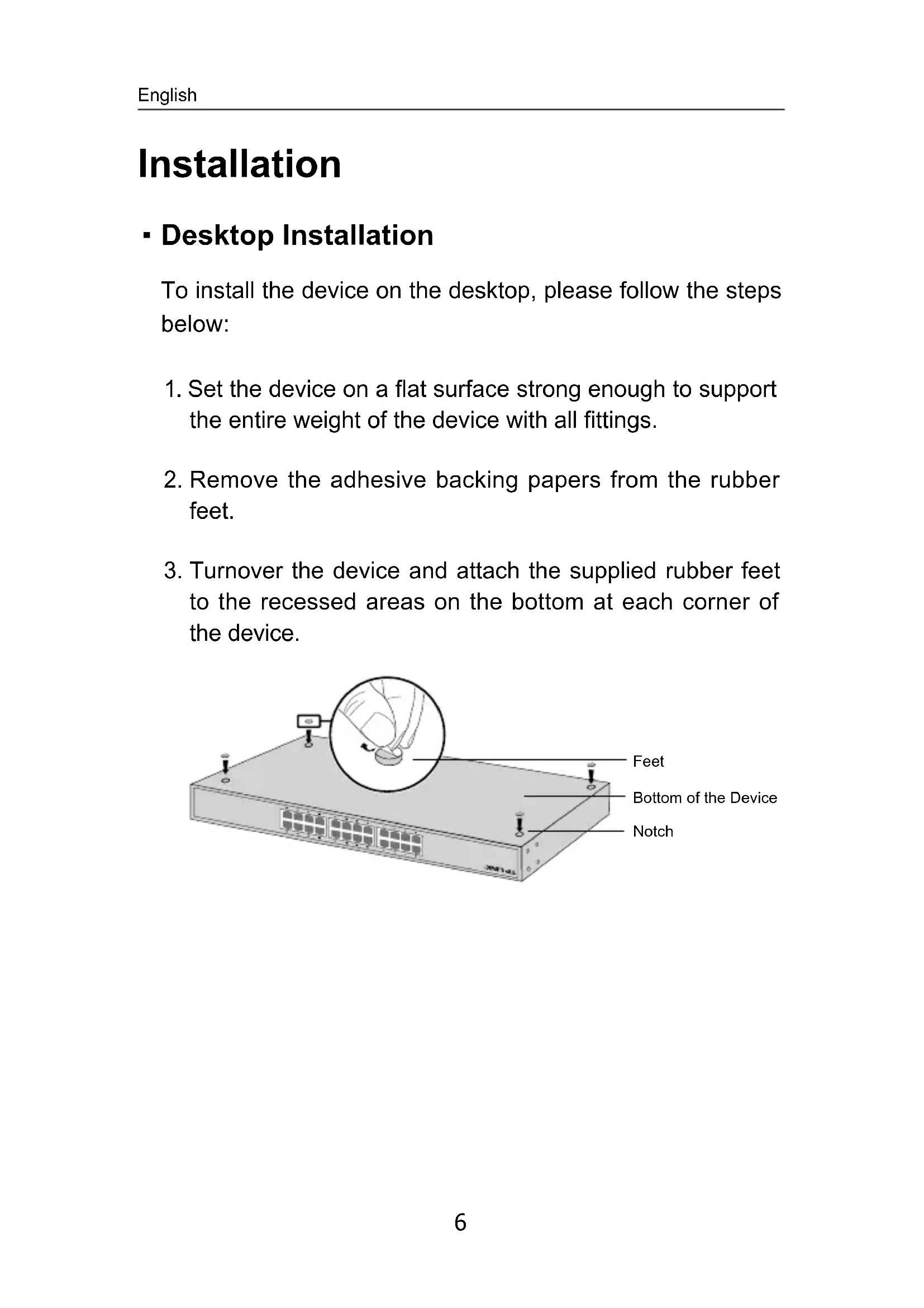
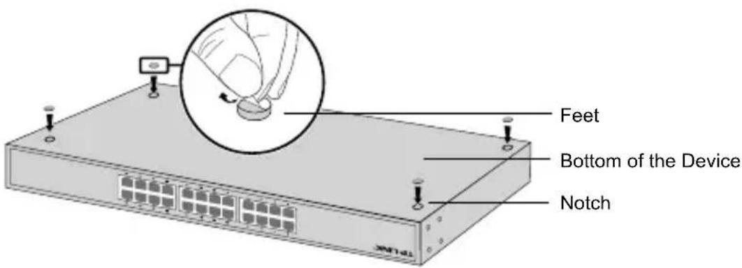
To install the device on the desktop, please follow the steps below:
- Set the device on a flat surface strong enough to support the entire weight of the device with all fittings.
- Remove the adhesive backing papers from the rubber feet.
- Turnover the device and attach the supplied rubber feet to the recessed areas on the bottom at each corner of the device.
- Rack Installation
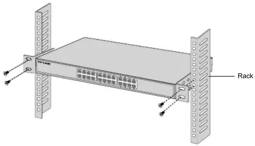
To install the device in a rack, follow the instructions described below:
- Check the grounding and stability of the rack.
- Secure the supplied rack-mounting brackets to each side of the device with supplied screws.
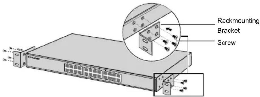
- After the brackets are attached to the device, use suitable screws (not provided) to secure the brackets to the rack.
Connection
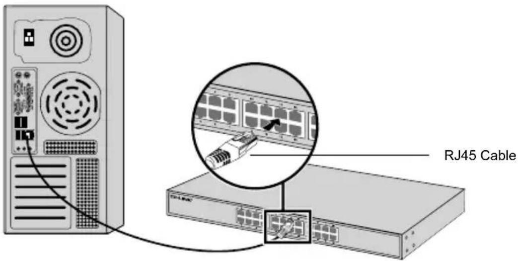
- Ethernet Port
Connect an Ethernet port of the switch to the computer by RJ45 cable as the following figure shown.
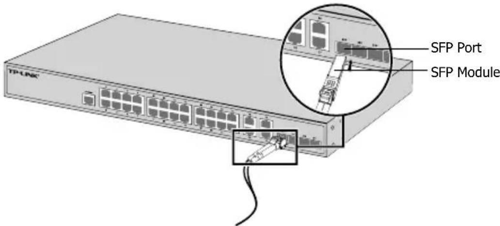
- SFP Port
For switches with SFP ports, you can connect a SFP port to a SFP module. If an SFP transceiver is installed in a slot and has a valid link on the port, the associated RJ45 port will be disabled and cannot be used.
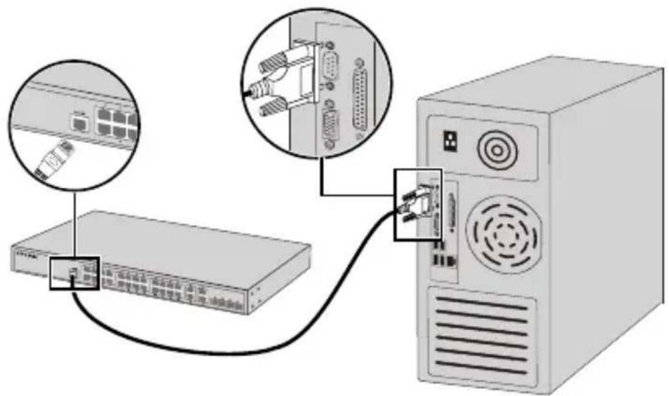
- Console Port
For switches with the console port, you can connect the console port with your computer by the console cable. Then you can load the CLI to manage the switch.
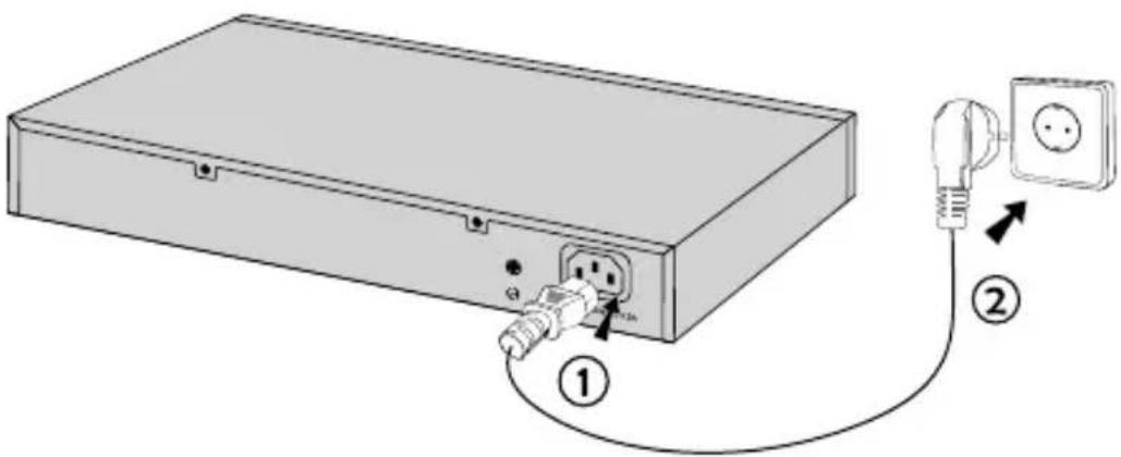
- Power On
Plug the female connector of the provided power cord into the power socket of the device, and the male connector into a power outlet.
Configuration
- Configure the Switch Using the GUI
- Set the IP address of your PC in the same subnet of the switch. The IP address is 192.168.0.x("x" is any number from 2 to 254); the Subnet Mask is 255.255.255.0.
- Open a web browser and type the default management address http://192.168.0.1 in the address field of the browser, then press the Enter key.
- Enter admin for the default User Name and Password, both in lower case letters. Then click the Login button or press the Enter key.
- After a successful login, you can configure the switch on the management page.
- Configure the Switch Using the CLI (Only for Smart Switches and Managed Switches)
You can log on to the switch and access the CLI to manage the switch. For the detailed instructions as to how to do this, please refer to the CLI Guide.
- Configure the Switch Using the Utility (Only for Easy Smart Switches)
You can use the Easy Smart Configuration Utility to centrally manage entire networks of the Easy Smart Switches. For the detailed instructions as to how to do this, please refer to the Utility User Guide.
Instalación
- Puerto SFP
- Encender
Configuración
- Θúpa Console
- Ενεργοποιήστε
Ρύθμιση
Configuration
- Configurer le switch via son interface graphique
- Accensione
Configurazione
- Configure lo Switch usando la GUI
- Ligar
Configuração
- Configurar o Switch via Interface gráfica
- Virta päällä
Konfigurointi
- Konfiguroi kytkin GUI:lla
- Inschakelen
Configuratie
- Desktop-installation
- Ström på
Konfiguration
- For å slå på
Konfigurasjon
- Tændt
Konfiguration
- Cihazı Çalıştırma
Yapılandırma
- When a product has a power on/off button, the power on/off button is one way to turn-off the product. For products without the on/off button, the only way to completely turn-off the product is to disconnect the product or the power adapter from the power source. The disconnected device shall remain readily operable.
- Do not open this product or attempt to service it; it may expose you to dangerous high voltage or other risks. Opening a sealed component or sealed product/s will void the warranty. For product servicing, please contact us.
- Do not operate this product near water.
TP-LINK Limited Product Warranty
For TP-LINK Branded Products Only.
THIS WARRANTY GIVES YOU SPECIFIC LEGAL RIGHTS, AND YOU MAY HAVE OTHER RIGHTS THAT VARY FROM STATE TO STATE (OR BY COUNTRY OR PROVINCE).
TO THE EXTENT ALLOWED BY LOCAL LAW, THIS WARRANTY AND THE REMEDIES SET FORTH ARE EXCLUSIVE AND IN LIEU OF ALL OTHER WARRANTIES, REMEDIES AND CONDITIONS.
TP-LINK warrants the TP-LINK branded hardware product contained in the original packaging against defects in materials and workmanship when used normally in according with TP-LINK's guidelines for some period which depends on the local service from the date of original retail purchase by the end-user purchaser.
Español
South Building(floors 1,3,4,5) and 28(floors 1-4), Central Science & Technology Park, Shennan Rd, Nanshan, Shenzhen, China
Robert-Bosch-Straße 9, 65719 Hofheim am Taunus, Germany
Unit 2 & 3 Riverview (142-144), Cardiff Road, Reading, RG1 8EW
Marathonodromou 77, Marousi 151 24, Greece
Specifications are subject to change without notice. TP-LINK is a registered trademark of TP-LINK TECHNOLOGIES CO., LTD. Other brands and product names are trademarks or registered trademarks of their respective holders. No part of the specifications may be reproduced in any form or by any means or used to make any derivative such as translation, transformation, or adaptation without permission from TP-LINK TECHNOLOGIES CO., LTD. Copyright © 2016 TP-LINK TECHNOLOGIES CO., LTD. All rights reserved.


- Easy Smart&Smart&Managed Rackmount Switch
- CONTENTS
- Installation
- - Tischmontage
- - SFP-Port
- - Einschalten
- Konfiguration
- - Desktop Installation
- - Rack Installation
- Connection
- - Ethernet Port
- - SFP Port
- - Console Port
- - Power On
- Configuration
- - Configure the Switch Using the GUI
- - Configure the Switch Using the CLI (Only for Smart Switches and Managed Switches)
- - Configure the Switch Using the Utility (Only for Easy Smart Switches)
- Instalación
- - Puerto SFP
- - Encender
- Configuración
- - Θúpa Console
- - Ενεργοποιήστε
- Ρύθμιση
- - Configurer le switch via son interface graphique
- - Accensione
- Configurazione
- - Configure lo Switch usando la GUI
- - Ligar
- Configuração
- - Configurar o Switch via Interface gráfica
- - Virta päällä
- Konfigurointi
- - Konfiguroi kytkin GUI:lla
- - Inschakelen
- Configuratie
- - Desktop-installation
- - Ström på
- - For å slå på
- Konfigurasjon
- - Tændt
- - Cihazı Çalıştırma
- Yapılandırma
- TP-LINK Limited Product Warranty
- Español
Brand : TP-LINK
Model : T1600G28TS
Category : Switch