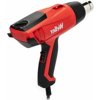
6966EK - Heat gun Weller - Free user manual and instructions
Find the device manual for free 6966EK Weller in PDF.


User questions about 6966EK Weller
0 question about this device. Answer the ones you know or ask your own.
Ask a new question about this device
Download the instructions for your Heat gun in PDF format for free! Find your manual 6966EK - Weller and take your electronic device back in hand. On this page are published all the documents necessary for the use of your device. 6966EK by Weller.
USER MANUAL 6966EK Weller
Table of contents Pages
- About these instructions 7
- For your safety 7
- Scope of supply 8
- Device description 8
5.Setting up the device 9 - Operation 9
7.Special faults 10 - Care and maintenance 12
- Fault messages / fault correction 12
- Accessories 12
- Disposal 12
12.Warranty 13
Table des matieres
Always place the soldering tool in the safety rest while not in use.
- Display
-
- button
-
- button
- DC connection
- Connecting socket for soldering tool
- Disconnecting switch for battery
- Potential balancing socket
- Temperature display
- Temperature symbol
- Time function
- Lock
- Fixed temperature 2
- Battery status
- Fixed temperature 1
- Offset
16.Setback - Off
- Standby
- Funnel insert
- Holder spring
- Safety rest
- Rubber mounts
- Container with wool ball
- Handle
- RT soldering tip
- Switching power supply
1. About these instructions
Thank you for placing your trust in our company by purchasing the Weller WSM 1 / WSM 1C. The device has been manufactured in accordance with the most rigorous quality standards to ensure that the device operates perfectly.
These instructions contain important information for safe and correct initial operation of the WSM 1 / WSM 1C soldering station, including continued operation, maintenance and self-correction of simple faults.
③ Read these instructions and the accompanying safety information carefully before switching on the device and starting work with the soldering station WSM 1 / WSM 1C.
③ Make sure that all users have access to these instructions.
1.1 Applied directives
The Weller microprocessor-controlled soldering station WSM 1 / WSM 1C conforms to the specifications of the EC Declaration of Conformity with Directives 2004/108/EC, 2006/95/EC and 2011/65/EU (RoHS).
1.2 Further applicable documentation
- Operating instructions for soldering station WSM 1 / WSM 1C
- Safety information booklet accompanying these instructions
2. For your safety
The WSM 1 / WSM 1C soldering station has been manufactured in accordance with state-of-the-art technology and recognised technical safety regulations. There is nevertheless a risk of personal injury and damage to property if the safety information set out in the accompanying safety booklet and the warnings presented in these instructions are not observed. Always pass on the WSM 1 / WSM 1C soldering station to third parties together with these operating instructions.
2.1 Specified use
Use the WSM 1 / WSM 1C soldering station exclusively for the purpose indicated in the operating instructions of soldering and unsoldering under the conditions specified. Specified use of the WSM 1 / WSM 1C soldering station also includes
- observing these operating instructions,
- observing all other accompanying documentation,
- observing locally applicable accident prevention regulations.
The manufacturer shall not be liable for damage resulting from unauthorised alterations to the device.
2.2 Information on the battery and switching power supply
The device is supplied by a switching power supply or battery. The battery can be discharged and recharged several hundred times but will inevitably wear down over time. If charging intervals become shorter than normal, replace the battery.
If service is required, send in the whole appliance - do not remove the rechargeable battery and send it separately. The appliance should be switched off and the soldering tip removed, as otherwise special hazardous goods regulations apply.
Always use batteries and chargers approved by Weller that are designed for this purpose. Charge the battery completely before operating the station in cordless mode for the first time or if you do not intend to use the battery for long periods. A fully charged battery will discharge over time. Always use the battery for the designated purpose. Never use a damaged charger or battery.
Do not short-circuit the battery. Short-circuiting the poles may damage the battery or the connected devices. Extreme temperatures reduce the capacity and service life of the battery. Therefore always try and store the battery at temperatures between 15^ and 25^ (59°F and 77°F). Under certain circumstances, a device with a cold or warm battery may not function temporarily, even if the battery is fully charged. The performance of the batteries is restricted at temperatures significantly lower than freezing point.
Do not throw batteries into fire: risk of explosion! Batteries can also explode when damaged. Always dispose of batteries according to regulations. Deposit at a recycling centre if possible. Consumers are required by law to take used regular and rechargeable batteries to a suitable waste collection centre.
Do not dispose of with the household waste. Do not attempt to open or destroy batteries. If fluid begins to escape from a battery, make sure that it does not come into contact with your skin or eyes. If contact is unavoidable, rinse the affected area immediately with water or seek immediate medical attention.
The power packs Weller uses have a wide input range and are therefore suitable for connection to the mains voltage range specified in the technical data.
The power pack must only be used in dry environments. The device generates heat during operation.

For shipping, the RT soldering tip (25) should be removed and the isolating switch (6) should be set to "0" (rechargeable battery version) to avoid unwanted switch-on.
Caution: fire hazard!
3. Scope of supply
WSM1/WSM1C
Mains cable
Switching power supply
Jack connector
Soldering iron with RT 3 soldering tip
Safety rest with dry cleaning
Operating instructions
Safety booklet
4. Device description
The Weller soldering station WSM 1 / WSM 1C is a versatile soldering station for performing professional repair work on state-of-the-art electronic assemblies in the industrial engineering sector as well as repair workshops and laboratories.
Digital control technology and superior sensor and heat-transfer technology guarantee precise temperature control at the soldering tip. High-speed measured-value acquisition provides for maximum temperature precision and optimum dynamic temperature performance in load situations.
The required temperature setting can be adjusted between 100^ - 400^ . Setpoint and actual values are displayed in digital form.
Application note for battery:
- Fully charge the battery prior to initial operation or longer periods of disuse.
- Set the disconnecting switch (6) to "I".
- It is advisable to fully charge the battery at least once a month.
- Store and use the battery at room temperature.
- Before storing the device for long periods, charge the battery to a minimum charge of 50% and set the disconnecting switch (6) to "0".
- The standby function adapts the device according to the mode of use and may increase the battery service life.
4.1 Safety rest
Attach the holder spring (20) with funnel insert (19) by inserting the clamp on the holder spring in the recess on the safety rest (21).
Insert the steel wool into the housing section (23). Place the housing section onto the safety rest and secure with rubber mounts (22).
4.2 Technical data WSM 1 / WSM 1C
Dimensions: L x B x H (mm): 133 x 110 x 55
LxBxH (inch): 5.24× 4.33× 2.17
Weight: approx. 2.0kg
Mains voltage: 100V to 240V
50 Hz to 60 Hz
Power consumption: 50 W
WSM 1 Safety class: I
WSM 1C Safety class (switching power supply): II
WSM 1C Safety class (battery version): III
Temperature control: 100^ - 400^
(200^ - 750^)
Temperature accuracy: ± 9^ (± 17^)
Temperature stability: ± 5^ (± 9^)
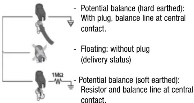
Potential balance: Via 3.5 mm pawl socket
on back of device (7).
Operating range: 10^ - 35^
(50°F-95°F)
Storage temperature: -24^ - 45^
(-75^ - 113^)
Rel. air humidity: 0% - 90% , not condensing
Note the following specifications when using the battery:
Maximum operating height:
3,000 m above sea level, no pressure compensation
Maximum storage height:
4,500 m above sea level, no pressure compensation
Maximum transportation height:
10,500 m above sea level, no pressure compensation
Potential balance for WSM 1 / WSM 1C
3 variants are available by connecting the 3.5mm pawl connector (7) differently:
5. Setting up the device

WARNING!
Electric shock and risk of burns
Connecting the control unit incorrectly poses a risk of injury and damage to the device. Risk of burns from the soldering tool while the control unit is operating.
Read the enclosed instructions, the safety instructions included in these operating instructions as well as the instructions for your control unit all the way through and observe the specified precautionary measures before operating the control unit.
⑤ Always place the soldering tool in the safety rest when not in use.
⑤ Disconnector is not for mains disconnection!
⑤ Switch off disconnector when not in use ("0" position).
- Carefully unpack the device.
- When fitting the new soldering tip, make sure that the soldering tip is inserted all the way up to the stop in a single smooth action. Operating the soldering iron with a soldering tip that is not fully inserted can cause malfunctions.

Important:
Always ensure that the soldering tip is seated properly.
- Place the soldering tool in the safety rest.
- Check whether the mains supply voltage matches the specification indicated on the rating plate and whether the disconnecting switch (6) is off, battery version only.
- Connect the control unit to the mains power using the power pack (26). Set the disconnecting switch (6) to "I" to charge the battery. The display (1) shows "OFF".
- BAT (10) is flashing to indicate charging process.
- Press the + (2) and (-3) buttons for approx. 1 sec to switch "ON" the device, "ON" appears on the display (1).
The electronics automatically switch to the actual value display.
6. Operation
6.1 Setting the temperature
Setting the temperature individually
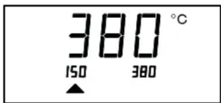
- Press the + or - button.
The display switches to the setpoint value. The temperature symbol (8) flashes. - Press the + or - button to set the required setpoint temperature
- Touching the button briefly alters the setpoint value by one degree Celsius / Fahrenheit
- Pressing the button permanently alters the setpoint value in rapid pass mode.
The actual value appears on the display again approx. 2 seconds after the buttons are released.
6.2 Soldering
Handling soldering tips
- Coat the tin-plated soldering tip with solder when heating the iron for the first time to remove any oxide films or impurities from the soldering tip that have accumulated during storage.
- During pauses between soldering and before storing the soldering iron, ensure that the soldering tip is wellcoated.
- Do not use aggressive fluxing agents.
- Always ensure that the soldering tip is seated properly.
- Select the lowest possible working temperature.
- Select the largest possible soldering tip shape for the application.
Rule of thumb: approx. as large as the component or mounting surface on the printed circuit board
- Coat the soldering tip well to ensure efficient heat transfer between the soldering tip and soldering point.
- Switch off the system if you do not intend to use the soldering iron for longer periods or activate the Weller temperature reduction function.
- Coat the tip before placing the soldering iron in the safety rest.
- Apply the solder directly at the soldering point, not on the soldering tip.
- Do not subject the soldering tip to physical force.
Note:
The power units have been adapted to hold a medium-sized soldering tip. Discrepancies may occur if the tip is changed or a different shaped tip is used, but these can be overcome using the offset function.
6.3 Switching off the device
Press the + and - button until "OFF" appears on the display
Note
If you do not intend to use the soldering iron for longer periods, set the disconnecting switch to "0".
Make sure that the battery is charged at least 50% , see Information on the application note for battery on page 8.
Soldering tip change
Caution, risk of burning!
Tools are not required to change the soldering tip.
Only change a cold soldering tip.
The soldering tip is inserted in handle (24) and can be removed by simply pulling the soft grip on the soldering tip (25).

Important
- Change the soldering tip when cold.
- Always ensure that the soldering tip is seated properly.
6.4 Switching the temperature unit
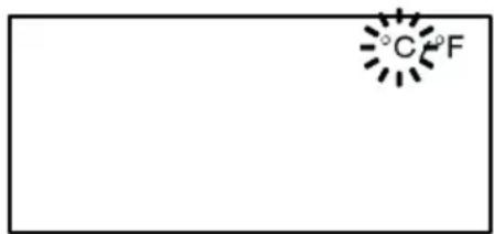
Switching the temperature unit from "°C to "F" (8) or vice versa.
- Select the menu item "°C / °F" in the menu.
- Set the temperature unit with the - or + button.
- The display reverts to the normal temperature if no buttons are pressed for about 2 seconds.
The stem is fitted with a sensor that monitors device use, i.e. when the stem is inserted in the rest, the temperature is reduced to standby temperature after 5 minutes and switched off after 5 more minutes.
7. Special functions for WSM 1 / WSM 1C
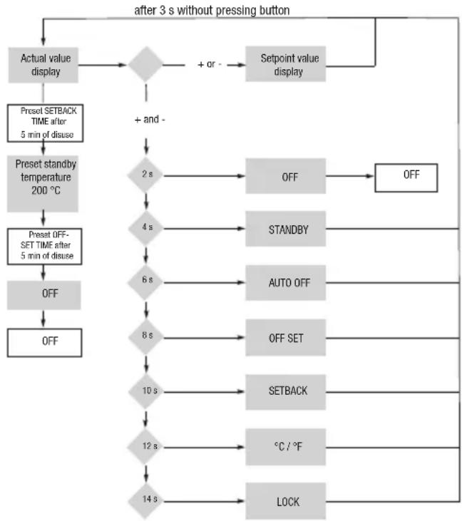
Setting the standby temperature
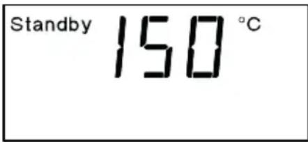
The following standby temperatures are available (150^ - 250^ / 300^ - 480^)
- Select the "STANDBY" (18) menu item in the menu.
- Set the setpoint value for the standby temperature with the - or + button.
- The display reverts to the normal temperature if no buttons are pressed for about 3 seconds.
Setting the automatic switch-off time (AUTO-OFF)
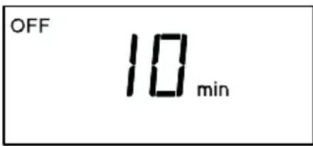
The following AUTO-OFF time settings (17) are available: - "10 - 60 min." AUTO-OFF time, individually adjustable
1. Select the menu item "OFF" in the menu.
2. Set the AUTO-OFF setpoint time value with the - or + button.
- The display reverts to the normal temperature if no buttons are pressed for about 3 seconds.
When the soldering tool is not in use, heating of the soldering tool is switched off after the AUTO-OFF time has elapsed.
Temperature deactivation is performed independently of the set setback function. 0 FF appears on the display.
Setting the temperature offset

The real soldering tip temperature can be adapted by entering a temperature offset around ± 40^ ( ± 72^ ).
- Select the "OFFSET" (15) menu item in the menu.
- Adjust the OFFSET temperature value with the - or + button.
- The display reverts to the normal temperature if no buttons are pressed for about 3 seconds.
Setting temperature deactivation (SETBACK)
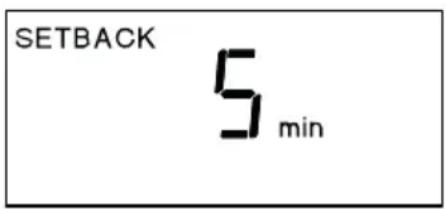
The following setback settings (16) are available: - "5-30 min": Setback (individually adjustable)
- Select the menu item "SETBACK" in the menu.
- Set the setback value with the - or + button.
- The display reverts to the normal temperature if no buttons are pressed for about 3 seconds.
When the soldering tool is not in use, the temperature is reduced to the standby temperature after the set setback time has elapsed. A flashing "STANDBY" symbol indicates setback status. Pressing the - or + button or moving the stem terminates setback status.
The stem is fitted with a sensor that monitors device use, i.e. when the stem is inserted in the rest, the stem is reduced to standby temperature after the preset setback time elapses. The stem is then switched off after the preset AUTO-OFF time elapses.
Switching the temperature unit
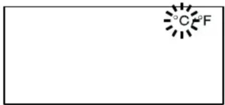
Switching the temperature unit from ^ C to ^ or vice versa.
- Select the menu item "C / F" (9) in the menu.
- Set the temperature unit with the - or + button.
- The display reverts to the normal temperature if no buttons are pressed for about 3 seconds.
Switching the lock function on/off
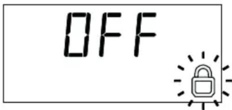
Once the lock is activated (11), only the fixed temperature buttons 1 (14) and 2 (15) work on the soldering station. All other settings are disabled until the repair station is unlocked again.
Lock the soldering station:
- Select lock from the menu. "OFF" appears on the display and the key symbol flashes.
- Enter the code (0-255) using the - or + key.
- The display reverts to the normal temperature if no buttons are pressed for about 3 seconds. The station is now locked.
Unlock the soldering station:
- Select lock from the menu.
The key symbol appears on the display. - Enter the code (0-255) using the - or + key.
- The display reverts to the normal temperature if no buttons are pressed for about 3 seconds. The station is now unlocked.
If you lose the access code, please contact Weller customer services.
8. Care and maintenance
Your device has been designed and manufactured with great care and should be handled with an equal degree of care. The following recommendation are designed to help you preserve your warranty and warranty claims.
- Store the device in a dry location. Precipitation, moisture and all types of liquid and fluid may contain minerals that can corrode the electronic circuits.
- Do not use or store the device in dusty or dirty environments. The moving parts and electronic components may be damaged.
- Do not store the device in hot environments and protect from sunlight. High temperatures may reduce the service life of electronic devices, damage batteries and deform or melt certain types of plastic.
- Do not store the device in cold environments. When the device reaches normal temperature after use, condensation may form inside and damage the electronic circuits.
- Do not attempt to open the device.
- Do not drop, shake or expose the device to impacts and bumps. Handling the device roughly may damage internal electronic circuits and delicate mechanical parts.
- Do not use aggressive chemicals, cleaning solvents or cleaning agents to clean the device.
- Clean the glass front with a soft, clean, dry cloth, a slightly moist cloth is also acceptable.
- Do not use the power pack outdoors.
These recommendations apply to your device, battery, power pack and any accessories. If your device ceases to function correctly, take it to your nearest authorised customer service centre.
9. Fault messages / Fault correction
Message / Possible Remedy Symptom cause
Display " - " - Tip faulty - Insert new
- Tip not soldering tip
inserted correctly
Display "BAT" (13) - Battery flat - Charge battery
- Turn
disconnecting
switch to "I" 6
Display does not - No operating - - Turn
function
voltage
disconnecting
(Display off) switch to "I"
(6) battery
version only)
- Check mains
power supply
- Charge battery
10. Accessories
T005 15 125 99 WDC 2 Dry cleaning insert
T005 13 841 99 Wool balls for WDC 2
T005 87 518 93 Power adapter
T0058751880
Car Adapter 12 V

Follow the safety safety instructions for the charging adapter.
Soldering tips for soldering iron WMRP, see overview on page 55-56.
Exploded drawing, see page 57
11. Disposal
Dispose of replaced device parts or old devices in accordance with national regulations.
The symbol of the crossed-out waste bin on the product, in the documentation or on the packaging material means that within the European Union, electrical and electronic products, batteries and accumulators must be deposited at an appropriate recycling centre at the end of their useful life. Do not dispose of these products with the unsorted household waste.
Dispose of these product separately from other waste to prevent damage to the environment and the health of humans through unregulated waste disposal and promote the sustained reuse of material resources. You can obtain information on separate waste disposal from your local dealer, the relevant authorities or national manufacturing organisations.
12. Warranty
Claims based on defects will fall under the statute of limitations 12 months after delivery to the purchaser of the goods. This shall not apply to rights of recourse of the purchaser according to sections 478, 479 German Civil Code.
We shall assume liability for warranties supplied by us only if the quality guarantee or service warranty has been submitted in writing and using the term "Warranty".
Subject to technical alterations and amendments!
See the updated operating instructions at www.weller-tools.com.
Dimensions: L x I x H (mm): 133 x 110 x 55
$$ L \times I \times H (\text {p o u c e s}): 5. 2 4 \times 4. 3 3 \times 2. 1 7 $$
Poids: env. 2,0 kg
1.1 Directive considerate
L x P x H (inch): 5.24 x 4.33 x 2.17
Peso: ca. 2,0 kg
interruptor principal
"I" (6)
C x L x A (inch): 5.24 x 4.33 x 2.17
Peso: aprox. 2,0 kg
4th Floor Pennine House
Washington, Tyne & Wear
NE371LY
Phone: +44 (0) 191 419 7700
Fax: +44 (0) 191 417 9421
FRANCE
Apex Tool Group SNC
25 Avenue Maurice Chevalier
77832 Ozoir-la-Ferriere
Phone:+33 (0) 1.64.43.22.00
Fax: +33 (0) 1.64.43.21.62
ITALY
Apex Tool S.r.l.
Viale Europa 80
20090 Cusago (MI)
Phone: +39 (02) 9033101
Fax: +39 (02) 90394231
SWITZERLAND
Apex Tool Switzerland Sarl
Cret-St-Tombet 15
2022 Bevaix
Phone: +41 (0) 24 426 12 06
Fax: +41 (0) 24 425 09 77
INDIA
Apex Power Tools India Pvt. Ltd.
Regus business centre,
Level 2, Elegance, Room no. 214
Mathura Road, Jasola,
New Delhi - 110025
AUSTRALIA
Apex Tool - Australia
P.O.Box 366
519 Nurigong Street
Albury, N. S. W. 2640
Phone: +61 (2) 6058-0300
Fax: +61 (2) 6021-7403
CANADA
Apex Tools - Canada
5925 McLaughlin Rd.
Mississauga
Ontario L5R 1B8
Fax: +1 (905) 387-2640
CHINA
Apex Tool Group
A-8 Building, No 38 Dongsheng Road
Heqing Industrial Park, Pudong,
Shanghai 201201 China
Phone: +86 (21) 60 88 02 88
Fax: +86 (21) 60 88 02 89
USA
Apex Tool Group, LLC
14600 York Rd. Suite A
Sparks, MD 21152