EYFLA3 - Cordless drill PANASONIC - Free user manual and instructions
Find the device manual for free EYFLA3 PANASONIC in PDF.
| Product type | Cordless hammer drill |
| Brand | Panasonic |
| Model | EYFLA3 |
| Rated voltage | 10.8 V DC |
| Battery capacity | 3 Ah |
| Battery type | Li-ion (model EYFB30) |
| No-load speed (max) | 0 – 2300 rpm |
| Impacts per minute (max) | 0 – 4000 min⁻¹ |
| Maximum torque | 120 N·m |
| Torque control range | 16 – 53 N·m |
| Chuck type | Quick hex 1/2" (12.7 mm) |
| Overall length | 164 mm |
| Weight (with battery) | 1.35 kg |
| Compatible charger | EY0L80 |
| Main functions | Drilling, screwdriving with torque control, impact tightening, auto stop, battery charge indicator, LED light, wireless remote control (optional) |
| Maintenance and cleaning | Clean with a dry, clean cloth; do not use water, solvent, or volatile products |
| Safety | Ear protection recommended, avoid contact with metal parts when drilling into walls, lock switch in center position, pay attention to battery temperature |
| Included accessories | Li-ion battery EYFB30, charger EY0L80, remote control EYFA30 (optional) |
| General information | Instructions available in multiple languages, battery and WEEE recycling compliant with EU directives |
Frequently Asked Questions - EYFLA3 PANASONIC
User questions about EYFLA3 PANASONIC
0 question about this device. Answer the ones you know or ask your own.
Ask a new question about this device
Download the instructions for your Cordless drill in PDF format for free! Find your manual EYFLA3 - PANASONIC and take your electronic device back in hand. On this page are published all the documents necessary for the use of your device. EYFLA3 by PANASONIC.
USER MANUAL EYFLA3 PANASONIC
Before operating this unit, please read these instructions completely and save this manual for future use.
English: Page 6 Dansk: Side 83
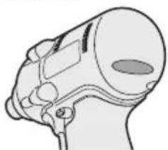
This tool is a Cordless Impact Driver/Wrench and can be used to tighten bolts, nuts, and screws. Additionally, it provides a torque control function that automatically stops tool operation when a preset load is reached to deliver consistent tightening torque.
Read "the Safety Instructions" booklet and the following before using.
II. ADDITIONAL SAFETY RULES
1) Wear ear protectors when using the tool for extended periods.
2) Be aware that this tool is always in an operating condition, since it does not have to be plugged into an electrical outlet.
3) When screwing or driving into walls, floors, etc., "live" electrical wires may be encountered. DO NOT TOUCH THE HEX QUICK CHUCK OR ANY FRONT METAL PARTS OF THE TOOL! Hold the tool only by the plastic handle to prevent electric shock in case you screw or drive into a "live" wire.
4) Do NOT operate the Forward/Reverse lever when the main switch is on. The battery will discharge rapidly and damage to the unit may occur.
5) During charging, the charger may become slightly warm. This is normal.
Do NOT charge the battery for a long period.
6) When storing or carrying the tool, set the Forward/Reverse lever to the center position (switch lock).
7) Do not strain the tool by holding the speed control trigger halfway (speed control mode) so that the motor stops.
| Symbol | Meaning |
| V | Volts |
| --- | Direct current |
| n_0 | No load speed |
| ... min^-1 | Revolutions or reciprocations per minutes |
| Ah | Electrical capacity of battery pack |
 | Read the operating instructions before use. |
 | For indoor use only. |
III. ASSEMBLY
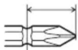
Attaching or Removing Bit
NOTE:
- When attaching or removing a bit, disconnect battery pack from tool or place the switch in the center position (switch lock).
- Hold the collar of quick connect chuck and pull it out from the tool.
- Insert the bit into the chuck. Release the collar.
- The collar will return to its original position when it is released.
- Pull the bit to make sure it does not come out.
- To remove the bit, pull out the collar in the same way.
CAUTION:
- If the collar does not return to its original position or the bit comes out when pulled on, the bit has not been properly attached. Make sure the bit is properly attached before use.
EYFLA1A/EYFLA2A
12 mm (15/32")
9 mm - 9.5 mm (23/64" - 3/8")
6.35 mm (1/4")
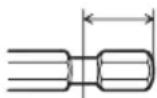
Attaching Socket
- Remove the socket's rubber ring and pin.
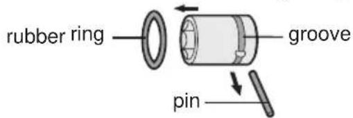
① Attach the socket to the tool.
② Insert the pin. (Taking care to align the pin holes on the socket and tool.)
③ Attach the rubber ring by sliding it into place over the groove.
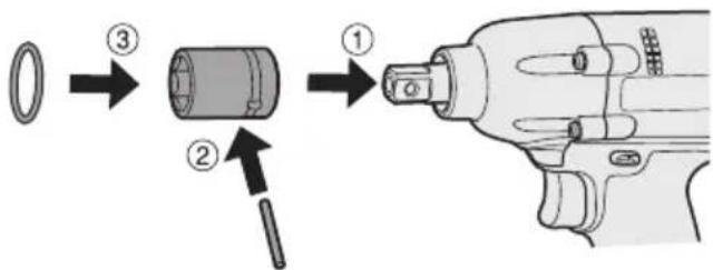
NOTE:
Be sure to attach the rubber ring to prevent the pin from falling out.
Removing Socket
① Remove the rubber ring.
② Remove the pin.
③ Remove the socket from the tool.
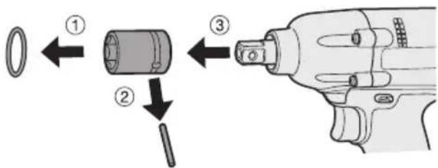
NOTE:
Keep the temperature of the tool above the freezing point (0°C/32°F) when attaching sockets to or detaching them from the square drive on the tool. Do not use excessive force when attaching or detaching sockets.
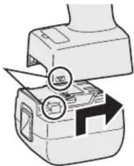
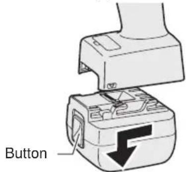
Attaching or Removing Battery Pack
- To connect the battery pack: Line up the alignment marks and attach the battery pack.
- Slide the battery pack until it locks into position.
Alignment marks
natural_image
Diagram of a printer with a magnified view showing the tip and base (no text or symbols)- To remove the battery pack: Push up on the button from the front to release the battery pack.
IV. OPERATION
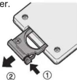
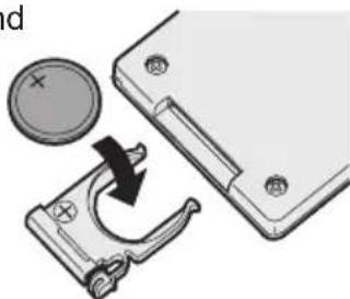
Before Using the Remote Control (Available as an optional accessory)
Insert the battery
- Pull out the battery holder.
① Push in on the fastener as indicated by the arrow.
② Pull out the holder.
- Insert the battery and push the holder back in.
natural_image
Mechanical assembly diagram showing a rotating component with a circular dial and arrow indicating rotation (no text or symbols)NOTE:
- If the tool does not respond to the wireless remote control even when the remote control is operated close to the tool, the battery (CR2025) is dead. Replace it with a fresh battery.
- The included battery is provided for sample use and may not last as long as commercially available batteries.
Wireless remote control range
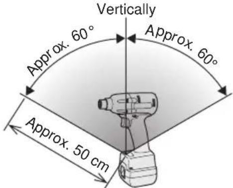
The remote control should be operated within approximately 50 cm and approximately 60° vertically and horizontally of the perpendicular relative to the infrared receiver on the tool.
- Under the following circumstances, you may not be able to operate the tool, even within this range.
- If there is an object between the remote control's transmitter and the tool's receiver.
- Use outdoors or in other environments where the remote control receiver is exposed to a strong light source, or when the remote control transmitter or receiver is dirty may cause the tool to fail to respond, even when the remote control is used within the operating range.
[Main Body]
Switch and Forward/Reverse Lever Operation

CAUTION:
To prevent damage, do not operate Forward/Reverse lever until the bit comes to a complete stop.
Forward Rotation Switch Operation
- Push the lever for forward rotation.
- Depress the trigger switch slightly to start the tool slowly.
- The speed increases with the amount of depression of the trigger for efficient tightening of screws. The brake operates and the bit stops immediately when the trigger is released.
- After use, set the lever to its center position (switch lock).
Reverse Rotation Switch Operation
- Push the lever for reverse rotation. Check the direction of rotation before use.
- Depress the trigger switch slightly to start the tool slowly.
- After use, set the lever to its center position (switch lock).
CAUTION:
- To eliminate excessive temperature increase of the tool surface, do not operate the tool continuously using two or more battery packs. Tool needs cool off time before switching to another pack.
Tightening confirmation lamp
- The tightening confirmation lamp can be used to check whether the torque control function was activated.
natural_image
Anatomical illustration of a human head and neck region (no text or labels)| Tool status Lamp display | |
| Tightening complete (with torque control function operation) | Green(For approx. 2 seconds) |
| • Tightening not complete• Tightening complete with retightening within 1 second | Red(For approx. 2 seconds) |
| The automatic stop function has been activated. | Red(For approx. 5 minutes) |
CAUTION:
- When the tool stops automatically after the switch is released during impact-mode tightening and then reengaged within 1 second, the red lamp will light up to indicate the risk of excessive torque application as a result of retightening.
NOTE
- The tightening confirmation lamp will not turn on under the following conditions:
- When the torque clutch is set to "F"
• During reverse rotation operation - The lamp turns off when the tool is in operation.
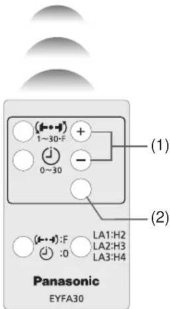
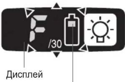
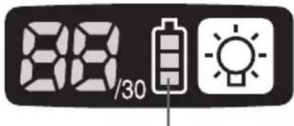
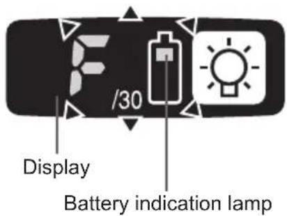
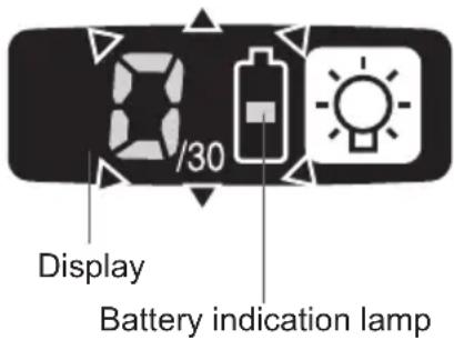
Control Panel
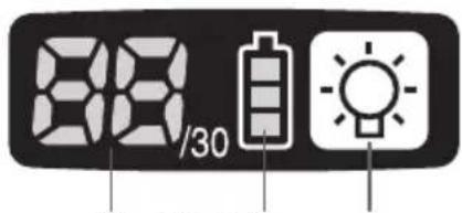
(1) (2) (3)
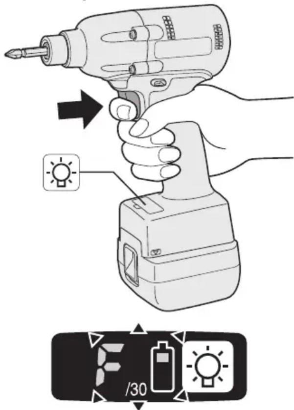
(1) LED light
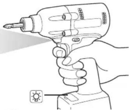
natural_image
Line drawing of a hand holding a screwdriver with a tool, no text or symbols presentPressing the button toggles the LED light on and off.
The light illuminates with very low current, and it does not adversely affect the performance of the tool during use or its battery capacity.
CAUTION:
- The built-in LED light is designed to illuminate the small work area temporarily.
- Do not use it as a substitute for a regular flashlight, since it does not have enough brightness.
Caution : DO NOT STARE INTO BEAM.
Use of controls or adjustments or performance of procedures other than those specified herein may result in hazardous radiation exposure.
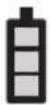
(2) The battery indication lamp
- Use the battery indication lamp to check how much power is left in the battery.
- Battery life varies slightly with ambient temperature and battery characteristics. The lamp is designed to provide a rough indication of remaining battery life.

Battery indication lamp
| Indicator Battery status | |
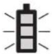
 | Fully charged |
 | Approx. 40% or less remaining |
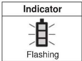
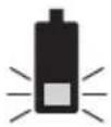 | Flashing Approx. 20% or less remaining (indicates need to recharge battery) |
| Flashing | The battery pack will need to be charged soon. |
 | No charge The battery pack needs to be charged. (The tool's automatic power-off function will activate at this stage.) |
| Flashing | |
Automatic power-off function
- The automatic power-off function is designed to prevent a loss of tightening torque due to reduced battery voltage. Once it has been activated, the tool will not operate until the battery pack has been charged (or replaced with a fresh unit), even if the trigger is depressed.
Battery indication lamp
NOTE:
- All 3 bars on the battery indication lamp will flash when the automatic power-off function is activated.
- When the battery indication lamp begins flashing, the battery pack should be charged (or replaced with a fresh unit) immediately.
- Be sure to fully charge the battery pack in question after activation of the automatic power-off function. Failure to do so may prevent the automatic power-off function from being properly deactivated.
(3) The torque control function
- The torque control function calculates the load from the motor's rotational angle during the hammer impact and determines that the bolt has been properly seated when a preset load value is exceeded. Driving is then automatically stopped after a preset number of impacts have been delivered to the bolt.
CAUTION:
- Always check the tool's tightening torque before use. Improper tool operation may result in excessive or inadequate tightening.
CAUTION:
- Always operate the tool with the switch fully engaged. The torque control function will not operate when the switch is not sufficiently engaged, preventing the tool from stopping automatically.
- In work where a heavy load comes to bear during tightening, the load may be interpreted as the seating of the bolt, preventing the bolt from being completely tightened.
- Repeated tightening of the same bolt may break the bolt or deform the material into which the bolt is being driven as a result of excessive tightening.
- The tightening torque value and precision vary with factors such as the material into which the bolt is being driven and the condition of the socket being used. Adjust the torque as necessary for the work being performed. Bolt tightening torque varies due to the factors described below.
1) Bolt
- Bolt diameter: Tightening torque generally increases with bolt diameter.
- Torque coefficient (indicated by the bolt manufacturer), grade, length, etc.
2) Other
- Bit and socket condition: Material, amount of play, etc.
- Use of a universal joint or socket adapter
- User: Manner in which the tool is applied to the bolt, strength with which the tool is held, manner in which the tool's switch is engaged
- Condition of object being tightened: Material, seating surface finish
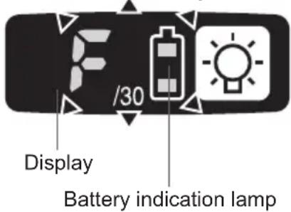
Setting the tool to configuration mode
- Turn off the control panel.
- If the control panel is on, remove and then reinsert the battery pack.
- Engage the switch while pushing the 📋 button and then release both the 📋 button and the switch.
• After all the LED lamps have turned off, the control panel will flash and change to configuration mode.
NOTE:
- Tools ship from the factory set to "F" mode (torque control function off).
- The control panel will turn off if the tool is not operated for a period of 5 minutes.
Configuring the torque clutch setting
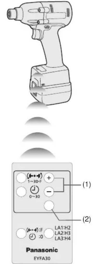
- Press the and buttons to select the clutch setting that is appropriate for the work being performed.
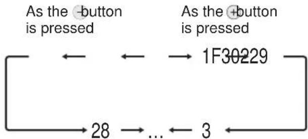
flowchart
graph LR
    A["As the -button is pressed"] <--> B["1F30229"]
    C["As the +button is pressed"] <--> B
    D["28"] --> E["..."]
    F["3"] --> E
    B --> E
- "F" indicates that the torque control function is off.
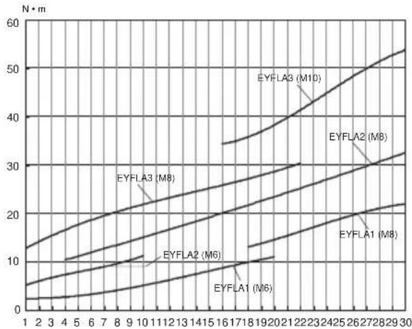
- You can select from 30 torque clutch settings (1 to 30). - Use figures from the Tightening Torque Chart to guide your selection of torque clutch setting. (See the following tightening torque chart)
- Press the OK button to accept the selected torque clutch setting.
- The control panel will stop flashing and light up.
CAUTION:
- You must press the OK button in order for the selected setting to take effect. - Be sure to verify the new value after changing the setting. (See page 12.)
Tightening Torque Chart (for Reference Use)
The values illustrated on this chart were measured under the conditions described below and are provided for reference purposes. Actual tightening torque varies with ambient conditions (the particular bolt being tightened, hardware being used, method of holding the bolt in place, etc.).
line
| Time | EYFLA1 (M6) | EYFLA2 (M6) | EYFLA3 (M6) | EYFLA1 (M8) | EYFLA2 (M8) | EYFLA3 (M10) | |------|-------------|-------------|-------------|-------------|-------------|--------------| | 1 | 2 | 4 | 6 | 8 | 10 | 12 | | 2 | 3 | 5 | 7 | 9 | 11 | 13 | | 3 | 4 | 6 | 8 | 10 | 12 | 14 | | 4 | 5 | 7 | 9 | 11 | 13 | 15 | | 5 | 6 | 8 | 10 | 12 | 14 | 16 | | 6 | 7 | 9 | 11 | 13 | 15 | 17 | | 7 | 8 | 10 | 12 | 14 | 16 | 18 | | 8 | 9 | 11 | 13 | 15 | 17 | 19 | | 9 | 10 | 12 | 14 | 16 | 18 | 20 | | 10 | 11 | 13 | 15 | 17 | 19 | 21 | | 11 | 12 | 14 | 16 | 18 | 20 | 22 | | 12 | 13 | 15 | 17 | 19 | 21 | 23 | | 13 | 14 | 16 | 18 | 20 | 22 | 24 | | 14 | 15 | 17 | 19 | 21 | 23 | 25 | | 15 | 16 | 18 | 20 | 22 | 24 | 26 | | 16 | 17 | 19 | 21 | 23 | 25 | 27 | | 17 | 18 | 20 | 22 | 24 | 26 | 28 | | 18 | 19 | 21 | 23 | 25 | 27 | 29 | | 19 | 20 | 22 | 24 | 26 | 28 | 30 | | 20 | 21 | 23 | 25 | 27 | 29 | 31 | | 21 | 22 | 24 | 26 | 28 | 30 | 32 | | 22 | 23 | 25 | 27 | 29 | 31 | 33 | | 23 | 24 | 26 | 28 | 30 | 32 | 34 | | 24 | 25 | 27 | 29 | 31 | 33 | 35 | | 25 | 26 | 28 | 30 | 32 | 34 | 36 | | 26 | 27 | 29 | 31 | 33 | 35 | 37 | | 27 | 28 | 30 | 32 | 34 | 36 | 38 | | 28 | 29 | 31 | 33 | 35 | 37 | 39 | | 29 | 30 | 32 | 34 | 36 | 38 | 40 | | 30 | - | - | - | - | - | - |Measurement conditions
• Temperature: Room temperature (20°C/68°F)
Using the Interval Set
- The interval set operates to prevent the tool from operating after it automatically stops as a result of the torque control function, even if the switch is engaged.
-
Set the tool to configuration mode. (See page 10.)
-
Press the interval set button.
- The control panel will begin flashing. Display: The number 0 flashes on and off. Battery indication lamp: The middle bar of the battery flashes on and off.
- Press the and buttons to set the desired time.
| Buttons Display Seconds | ||
  | 30 | 3 |
| ⋮ | ⋮ | |
| 1 0.1 | ||
| 0 Off | ||
- Press the OK button to accept the selected setting.
- The control panel will stop flashing and light up, and the torque clutch setting will be displayed.
CAUTION:
- Be sure to verify the new value after changing the setting.
Initializing All Settings
Factory settings
- Torque clutch setting: "F" (torque control function off)
-
Interval setting: 0 (off)
-
This section explains how to revert all tool settings to their default values at the time of shipment from the factory.
-
The error display will be turned off.
-
Set the tool to configuration mode. (See page 10.)
-
Press the format button.
- The control panel will begin flashing. Display: The letter "F" flashes on and off. Battery indication lamp: The upper and lower bars of the battery flash on and off.
- Press the OK button to accept the selected setting.
- The control panel will stop flashing and light up.
Checking Tool Settings
- This section describes how to have the tool display current settings for approximately 3 seconds when the tool is stopped.
- You cannot check tool settings when the control panel is turned off. First, engage the switch briefly to reactivate the display.
Checking the torque clutch setting
- Press the torque set button.
• Control panel display
Display: The torque set lights up.
Battery indication lamp: The upper bar of the battery flashes on and off.
Checking the interval
- Press the interval set button.
• Control panel display
Display: The interval set lights up.
Battery indication lamp: The middle bar of the battery flashes on and off.
Checking tool circuits
- Press the torque set button.
• Control panel display
Display: The torque set display lights up.
Battery indication lamp: The middle and lower bars of the battery flash on and off.
| Display Tool circuit | |
| H2 | EYFLA1 |
| H3 | EYFLA2 |
| H4 | EYFLA3 |
NOTE:
- If you engage the switch while a setting is being displayed, the control panel will revert to the torque clutch setting display.
CAUTION:
- The torque set display is not intended to be used to identify the type of drive component parts (hammer, etc.) used in a particular tool.
Error Display
In the event of a tool or battery pack malfunction, the control panel will display an error message. Please check the tool or battery pack as described in the following chart before having them serviced.
| Display Likely cause Corrective action | |||
| 81 | ▶ | Setting error Re-initialize the tool using the remote control. (See page 12.) | |
| 82 | ▶ | The battery pack is too hot. Stop work and allow the battery pack to cool before resuming use of the tool. | |
| 83 | ▶ | The tool is too hot to operate. Stop work and allow the tool to cool before resuming use. | |
| 84 | ▶ | The contacts that connect the battery pack and tool are dirty. | Remove any dirt. |
| The battery pack has not been properly inserted into the tool. | Insert the battery pack firmly into the tool. | ||
| The pins on either the tool or battery pack have worn down. | Replace the battery pack. | ||
| 85 | ▶ | Motor failure, etc. Stop using the tool immediately. | |
| 86 | ▶ | Sensor malfunction, failure, etc. | |
| 87 | ▶ | Tool circuit malfunction, failure, etc. | |
[Battery Pack]
For Appropriate Use of Battery Pack
Li-ion Battery Pack (EYFB30)
- For optimum battery life, store the Li-ion battery pack following use without charging it.
-
When charging the battery pack, confirm that the terminals on the battery charger are free of foreign substances such as dust and water etc. Clean the terminals before charging the battery pack if any foreign substances are found on the terminals.
The life of the battery pack terminals may be affected by foreign substances such as dust and water etc. during operation. -
When battery pack is not in use, keep it away from other metal objects like: paper clips, coins, keys, nails, screws, or other small metal objects that can make a connection from one terminal to another.
Shorting the battery terminals together may cause sparks, burns or a fire. - When operating the battery pack, make sure the work place is well ventilated.
- When the battery pack is removed from the main body of the tool, replace the battery pack cover immediately in order to prevent dust or dirt from contaminating the battery terminals and causing a short circuit.
natural_image
3D illustration of a rectangular electronic component with a recessed top and mounting hole (no text or symbols)Battery Pack Life
The rechargeable batteries have a limited life. If the operation time becomes extremely short after recharging, replace the battery pack with a new one.
Battery Recycling
ATTENTION:
For environmental protection and recycling of materials, be sure that it is disposed of at an officially assigned location, if there is one in your country.
[Battery Charger]
Charging
Read the operating manual for Panasonic battery charger for the battery pack before charging.
Before charging the battery
When charging EYFB30:
Charge the battery at a temperature of 5^ C ( 41^ F) to 40^ C ( 104^ F).
The battery pack cannot be charged at a temperature of less than 5^ C ( 41^ F). If the temperature of the battery pack is less than 5^ C ( 41^ F), first remove the battery pack from the charger and allow it to sit for an hour in a location where the temperature is 5^ C ( 41^ F) or warmer. Then charge the battery pack again.
Information for Users on Collection and Disposal of Old Equipment and used Batteries
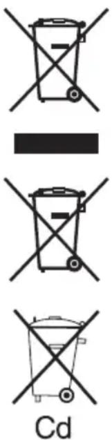
These symbols on the products, packaging, and/or accompanying documents mean that used electrical and electronic products and batteries should not be mixed with general household waste.
For proper treatment, recovery and recycling of old products and used batteries, please take them to applicable collection points, in accordance with your national legislation and the Directives 2002/96/EC and 2006/66/EC.
By disposing of these products and batteries correctly, you will help to save valuable resources and prevent any potential negative effects on human health and the environment which could otherwise arise from inappropriate waste handling.
For more information about collection and recycling of old products and batteries, please contact your local municipality, your waste disposal service or the point of sale where you purchased the items.
Penalties may be applicable for incorrect disposal of this waste, in accordance with national legislation.
For business users in the European Union
If you wish to discard electrical and electronic equipment, please contact your dealer or supplier for further information.
[Information on Disposal in other Countries outside the European Union]
These symbols are only valid in the European Union. If you wish to discard these items, please contact your local authorities or dealer and ask for the correct method of disposal.
Note for the battery symbol (bottom two symbol examples):
This symbol might be used in combination with a chemical symbol. In this case it complies with the requirement set by the Directive for the chemical involved.
V. MAINTENANCE
Use only a dry, soft cloth for wiping the unit. Do not use a damp cloth, thinner, benzine, or other volatile solvents for cleaning.
VI. ACCESSORIES
Charger
- EY0L80
Battery pack
- EYFB30
Remote control
- EYFA30
Protector for tool
- EYFA01-A (Blue)
- EYFA01-Y (Yellow)
- EYFA01-H (Gray)
Protector for battery
- EYFA02-H
VII. SPECIFICATIONS
MAIN UNIT
| Model EYFLA1 EYFLA2 EYFLA3 | |||||
| A A Q J | |||||
| Moter 10.8 V DC | |||||
| Chuck size | Single-ended | 9 - 9.5 mm(23/64" - 3/8") | 9 - 9.5 mm(23/64"-3/8") | ☐9.5 mm(3/8") | ☐12.7 mm (1/2") |
| Double-ended | 12 mm (15/32") | 12 mm(15/32") | |||
| No load speed | Stage | 1 0 - 950 | 1 | 0 - 1300 | 0 - 2300 |
| 2 0 - 1000 | 2 | 0 - 1450 | |||
| 3 - 5 0 - 1050 | 3 | 0 - 1550 | |||
| 6 0 - 1300 | 4 - 30·F | 0 - 2300 | |||
| 7 0 - 1450 | |||||
| 8 0 - 1550 | |||||
| 9 - 30·F 0 - 2300 | |||||
| Impact per minute | Stage | 1 0 - 1900 | 1 | 0 - 2500 | 0 - 3000 |
| 2 0 - 1950 | 2 | 0 - 2800 | |||
| 3 - 5 0 - 2100 | 3 | 0 - 3000 | |||
| 6 0 - 2500 | 4 - 30·F | 0 - 3600 | |||
| 7 0 - 2800 | |||||
| 8 0 - 3000 | |||||
| 9 - 30·F 0 - 4000 | |||||
| Maximum torque | 40 N·m(408 kgf-cm, 354 in-lbs) | 90 N·m(918 kgf-cm, 796 in-lbs) | 120 N·m (1224 kgf-cm,1062 in-lbs) | ||
| Torque control function operating range | Approx. 3 - 22 N·m(31 - 224 kgf-cm,27 - 195 in-lbs) | Approx. 6 - 30 N·m(61 - 306 kgf-cm,53 - 266 in-lbs) | Approx. 16 - 53 N·m(163 - 540 kgf-cm,142 - 469 in-lbs) | ||
| Overall length | 158 mm (6-7/32") | 164 mm (6-7/16") | |||
| Weight (with battery pack: EYFB30) | 1.3 kg (2.8 lbs) | 1.35 kg (2.9 lbs) | |||
BATTERY PACK (not included with shipment)
| Model EYFB30 | |
| Storage battery Li-ion battery | |
| Battery voltage 10.8 V DC (3.6 V/6 cells) | |
| Capacity 3 Ah | |
BATTERY CHARGER (not included with shipment)
| Model EY0L80 | |
| Rating See the rating plate on the bottom of the charger. | |
| Weight 0.95 kg (2.1 lbs) | |
[Li-ion battery pack]
| Charging time | 3 Ah | 10.8 V |
| EYFB30 | ||
| Usable: 40 min. | ||
| Full: 65 min. |
Remote control (not included with shipment)
| Model EYFA30 | |
| Battery voltage 3 V DC | |
| Dimensions 54 mm (2-1/8") × 86 mm (3-3/8") × 10 mm (13/32") | |
| Weight (with battery) Approximately 29 g (0.6 lbs) | |
ONLY FOR U. K.
VIII. ELECTRICAL PLUG INFORMATION
FOR YOUR SAFETY PLEASE READ THE FOLLOWING TEXT CAREFULLY
This appliance is supplied with a moulded three pin mains plug for your safety and convenience.
A 5 amp fuse is fitted in this plug.
Should the fuse need to be replaced please ensure that the replacement fuse has a rating of 5 amp and that it is approved by ASTA or BSI to BS1362.
Check for the ASTA mark or the BSI mark on the body of the fuse.
If the plug contains a removable fuse cover you must ensure that it is refitted when the fuse is replaced.
If you lose the fuse cover the plug must not be used until a replacement cover is obtained.
A replacement fuse cover can be purchased from your local Panasonic Dealer.
IF THE FITTED MOULDED PLUG IS UNSUITABLE FOR THE SOCKET OUTLET IN YOUR HOME THEN THE FUSE SHOULD BE REMOVED AND THE PLUG CUT OFF AND DISPOSED OF SAFELY.
THERE IS A DANGER OF SEVERE ELECTRICAL SHOCK IF THE CUT OFF PLUG IS INSERTED INTO ANY 13 AMP SOCKET.
If a new plug is to be fitted please observe the wiring code as shown below.
If in any doubt please consult a qualified electrician.
IMPORTANT:
The wires in this mains lead are coloured in accordance with the following code:
Blue: Neutral
Brown: Live
As the colours of the wire in the mains lead of this appliance may not correspond with the coloured markings identifying the terminals in your plug, proceed as follows.
The wire which is coloured BLUE must be connected to the terminal in the plug which is marked with the letter N or coloured BLACK.
The wire which is coloured BROWN must be connected to the terminal in the plug which is marked with the letter L or coloured RED.
Under no circumstances should either of these wires be connected to the earth terminal of the three pin plug, marked with the letter E or the Earth Symbol 12 .
How to replace the fuse: Open the fuse compartment with a screwdriver and replace the fuse and fuse cover if it is removable.
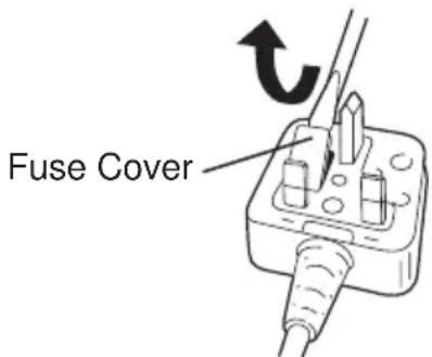
This apparatus was produced to BS800.
HINWEIS:
HINWEIS:
natural_image
Mechanical component diagram showing a clip attached to a bracket with numbered arrows indicating assembly steps (no text or symbols present)natural_image
Anatomical illustration of a human head and neck region, showing internal structures without any text or labels.natural_image
Line drawing of a hand holding a handheld electric drill with a light beam, no text or symbols presentHINWEIS:
natural_image
3D rendering of a mechanical component with a rectangular housing and mounting holes (no text or symbols)REMARQUE:
REMARQUE:
natural_image
Mechanical component with two arrows indicating assembly or disassembly (no text or symbols)natural_image
Mechanical assembly diagram showing a clamping mechanism with a coin and nut (no text or symbols)REMARQUE:
natural_image
Anatomical line drawing of a human head and neck region (no labels or text)natural_image
Line drawing of a hand holding a handheld electric drill, with no text or symbols present.REMARQUE:
line
| Time | EYFLA1 (M6) | EYFLA2 (M6) | EYFLA3 (M8) | EYFLA1 (M8) | EYFLA2 (M8) | EYFLA3 (M10) | |------|-------------|-------------|-------------|-------------|-------------|--------------| | 1 | 2 | 5 | 12 | 10 | 15 | 35 | | 2 | 3 | 6 | 14 | 12 | 17 | 37 | | 3 | 4 | 7 | 16 | 14 | 19 | 39 | | 4 | 5 | 8 | 18 | 16 | 21 | 41 | | 5 | 6 | 9 | 20 | 18 | 23 | 43 | | 6 | 7 | 10 | 22 | 20 | 25 | 45 | | 7 | 8 | 11 | 24 | 22 | 27 | 47 | | 8 | 9 | 12 | 26 | 24 | 29 | 49 | | 9 | 10 | 13 | 28 | 26 | 31 | 51 | | 10 | 11 | 14 | 30 | 28 | 33 | 53 | | 11 | 12 | 15 | 32 | 30 | 35 | 55 | | 12 | 13 | 16 | 34 | 32 | 37 | 57 | | 13 | 14 | 17 | 36 | 34 | 39 | 59 | | 14 | 15 | 18 | 38 | 36 | 41 | 61 | | 15 | 16 | 19 | 40 | 38 | 43 | 63 | | 16 | 17 | 20 | 42 | 40 | 45 | 65 | | 17 | 18 | 21 | 44 | 42 | 47 | 67 | | 18 | 19 | 22 | 46 | 44 | 49 | 69 | | 19 | 20 | 23 | 48 | 46 | 51 | 71 | | 20 | 21 | 24 | 50 | 48 | 53 | 73 | | 21 | 22 | 25 | 52 | 50 | 55 | 75 | | 22 | 23 | 26 | 54 | 52 | 57 | 77 | | 23 | 24 | 27 | 56 | 54 | 59 | 79 | | 24 | 25 | 28 | 58 | 56 | 61 | 81 | | 25 | 26 | 29 | 60 | 58 | 63 | 83 | | 26 | 27 | 30 | - | - | - | - | | 27 | - | - | - | - | - | - | | 28 | - | - | - | - | - | - | | 29 | - | - | - | - | - | - | | 30 | - | - | - | - | - | - | The data is already in CSV format with three columns: 'Time' and 'Distance'. The values are estimated based on the formula 'N·m' and 'Distance'. The labels above the lines are 'EYFLA3 (M8)' and 'EYFLA2 (M8)'. The numbers below the lines are 'EYFLA1 (M6)' and 'EYFLA2 (M8)'. The values above the lines are 'EYFLA3 (M10)' and 'EYFLA2 (M8)'. The values below the lines are 'EYFLA1 (M6)' and 'EYFLA2 (M8)'. The values above the lines are 'EYFLA3 (M10)' and 'EYFLA2 (M8)'. The values above the lines are 'EYFLA1 (M6)' and 'EYFLA2 (M8)'. The values above the lines are 'EYFLA3 (M10)' and 'EYFLA2 (M8)'. The values above the lines are explicitly labeled as 'EYFLA3 (M8)' and 'EYFLA2 (M8)'. The values above the lines are 'EYFLA1 (M6)' and 'EYFLA2 (M8)'. The values above the lines are also 'EYFLA3 (M10)' and 'EYFLA2 (M8)'. The values above the lines are also 'EYFLA1 (M6)' and 'EYFLA2 (M8)'.natural_image
3D rendering of a mechanical component with a rectangular housing and mounting holes (no text or symbols)NOTA:
NOTA:
natural_image
Mechanical component diagram showing a bracket with mounting holes and a curved slot, labeled with arrows (no text or symbols present)natural_image
Diagram showing a battery clip being inserted into a slot, with a coin partially visible (no text or symbols)NOTA:
natural_image
Technical line drawing of a mechanical device with no visible text or symbolsnatural_image
Line drawing of a hand holding a handheld electric drill with a light beam, no text or symbols presentNOTA:
| Display Circuito attrezzo | |
| H2 EYFLA1 | |
| H3 EYFLA | 2 |
| H4 EYFLA3 | |
NOTA:
natural_image
3D rendering of a rectangular electronic component with a recessed top and side slot (no text or symbols)OPMERKING:
OPMERKING:
natural_image
Mechanical component with two arrows indicating assembly or disassembly (no text or symbols)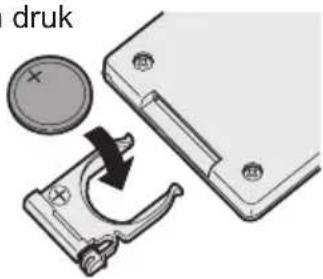
OPMERKING:
natural_image
Technical line drawing of a mechanical device with no visible text or symbolsnatural_image
Line drawing of a hand holding a handheld electric drill, with no text or symbols present.OPMERKING:
natural_image
Illustration of a hand using a drill bit to adjust a light bulb (no text or symbols present)
OPMERKING:
natural_image
3D rendering of a mechanical component with a rectangular housing and mounting holes (no text or symbols)NOTA:
NOTA:
natural_image
Diagram of a printer or scanner with a magnified view showing the tip and arrow (no text or symbols present)natural_image
Mechanical component diagram showing a clamping mechanism with numbered arrows (no text or symbols)
natural_image
Diagram showing a battery component being inserted into a housing, with a circular component and arrow indicating rotation (no text or symbols)NOTA:
natural_image
Anatomical illustration of a human head and neck region, showing internal structures without any text or labels.natural_image
Line drawing of a hand holding a handheld electric drill, with no text or symbols present.natural_image
Illustration of a hand using a screwdriver to adjust a light bulb (no text or symbols present)
NOTA:
natural_image
3D rendering of a gray plastic electronic component with a rectangular housing and a square slot (no text or symbols)BEMÆRK:
Sørg for at montere gummiringen for at forhindre stiften i at falde ud.
BEMÆRK:
natural_image
Mechanical component with two arrows indicating assembly or disassembly (no text or symbols)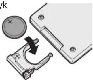
natural_image
Mechanical assembly diagram showing a clamping mechanism with a coin and nut, no text or symbols presentBEMÆRK:
natural_image
Line drawing of a mechanical device with no visible text or symbolsnatural_image
Line drawing of a hand holding a drill bit with a light bulb, no text or symbols presentBEMÆRK:
natural_image
3D rendering of a mechanical component with a rectangular housing and mounting holes (no text or symbols)Batteripakningens levetid
OBSERVERA:
OBSERVERA:
natural_image
Mechanical component diagram showing a bracket with mounting holes and a clamping mechanism, labeled with arrows (no text or symbols present)natural_image
Mechanical assembly diagram showing a clamping mechanism with a coin and nut (no text or symbols)OBSERVERA:
natural_image
Anatomical illustration of a human head and neck region (no text or labels)natural_image
Line drawing of a hand holding a drill bit with a tool, no text or symbols presentOBSERVERA:
natural_image
3D rendering of a mechanical component with a rectangular housing and mounting holes (no text or symbols)Festehylse
MERK:
Sikre at gummiringen festes for å forhindre at pinnen faller ut.
Fjerne hylsen
MERK:
natural_image
Mechanical component diagram showing a clamping mechanism with numbered arrows (no text or symbols)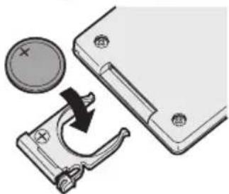
natural_image
Mechanical assembly diagram showing a battery pad moving into a clip with a coin inserted (no text or symbols)MERK:
natural_image
Anatomical illustration of a human head and neck with no visible text or labelsnatural_image
Line drawing of a hand holding a drill bit with a tool, no text or symbols presentMERK:
natural_image
3D rendering of a mechanical component with a rectangular housing and mounting bracket (no text or symbols)HUOMAUTUS:
HUOMAUTUS:
natural_image
Mechanical component diagram showing a clamping mechanism with arrows indicating assembly (no text or symbols)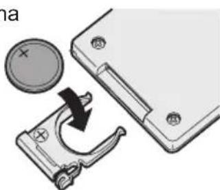
natural_image
Mechanical assembly diagram showing a rotating component with a circular dial and arrow indicating rotation (no text or symbols)HUOMAUTUS:
natural_image
Anatomical illustration of a human head and neck region (no labels or text)natural_image
Line drawing of a hand holding a drill bit with a power tool, no text or symbols presentHUOMAUTUS:
natural_image
3D rendering of a mechanical component with a rectangular housing and mounting holes (no text or symbols)Akun kestoikä
Ladattaessa malli EYFB30:
ПРИМЕЧАНИЕ
ПРИМЕЧАНИЕ
natural_image
Mechanical component diagram showing a clamping mechanism with labeled parts (①, ②), no text or symbols present.natural_image
Mechanical assembly diagram showing a clamping mechanism with a circular component and a separate housing (no text or symbols)ПРИМЕЧАНИЕ
natural_image
Technical line drawing of a mechanical device with no visible text or symbolsnatural_image
Line drawing of a hand using a power tool to apply light to a component, with no text or symbols present.natural_image
Illustration of a hand holding a drill pen and a power tool, with a light bulb icon indicating the right-hand rule (no text or symbols present)
ПРИМЕЧАНИЕ
natural_image
Line drawing of a handheld electric drill press (no text or symbols)