EY7547 - Cordless drill PANASONIC - Free user manual and instructions
Find the device manual for free EY7547 PANASONIC in PDF.

| Product type | Cordless drill |
| Brand | PANASONIC |
| Model | EY7547 |
| Voltage | 18 V DC |
| No-load speed (hard mode) | 0 - 2500 rpm |
| No-load speed (medium mode) | 0 - 1400 rpm |
| No-load speed (soft mode) | 0 - 1000 rpm |
| Impacts per minute (hard mode) | 0 - 3500 bpm |
| Impacts per minute (medium mode) | 0 - 2800 bpm |
| Impacts per minute (soft mode) | 0 - 2000 bpm |
| Maximum torque | 200 N·m |
| Overall length | 155 mm |
| Weight (with battery EY9L44) | 1.55 kg |
| Battery type | Rechargeable Li-ion |
| Compatible battery models | EY9L41, EY9L42, EY9L44, EY9L50 |
| Included charger | EY0L81 |
| Charging time (EY9L44) | 50 min (usable), 65 min (full) |
| Chuck | Quick hex 6.35 mm (1/4") |
| Impact power modes | Soft, Medium, Hard (selectable) |
| Overheat protection | Yes (auto stop, flashing indicator) |
| Low battery protection | Yes (flashing indicator before excessive discharge) |
| Protection rating | IP56 (dust and water jet resistance) |
| Integrated LED light | Yes, with dedicated switch |
| Belt hook | Yes, reversible (left/right) |
| Country of manufacture | Not specified in manual, but Japanese brand |
Frequently Asked Questions - EY7547 PANASONIC
User questions about EY7547 PANASONIC
0 question about this device. Answer the ones you know or ask your own.
Ask a new question about this device
Download the instructions for your Cordless drill in PDF format for free! Find your manual EY7547 - PANASONIC and take your electronic device back in hand. On this page are published all the documents necessary for the use of your device. EY7547 by PANASONIC.
USER MANUAL EY7547 PANASONIC
Original instructions: English Translation of the original instructions: Other languages
This tool, as a complete unit with a battery pack, satisfies appropriate IP Degrees of Protection based on the IEC regulations.
Definition of IP code
IP5X: Ingress of dust is not totally prevented, but dust shall not penetrate in a quantity to interfere with satisfactory operation of the tool or to impair safety (In case that the talcum powder under 75 m intrudes inside the tool) IPX6: Water projected in powerful jets against the tool from any direction shall have no harmful effects (In case that, with a nozzle of 12.5mm inner diameter, approximately 100 L/min of normal temperature water is injected to the tool for 3 minutes from 3 meter distance)
LIMITED WARRANTY
The rating of IP56 qualifies this tool for the minimum impact of water or dust, but not for the assurance of performance in such conditions. See Safety and Operating Instructions for further details for proper operation.
Read "the Safety Instructions" booklet and the following before using.
I. ADDITIONAL SAFETY RULES
1) Wear ear protectors when using the tool for extended periods.
2) Be aware that this tool is always in an operating condition, since it does not have to be plugged into an electrical outlet.
3) When screwing or driving into walls, floors, etc., "live" electrical wires may be encountered. DO NOT TOUCH THE HEX QUICK CHUCK OR ANY FRONT METAL PARTS OF THE TOOL! Hold the tool only by the plastic handle to prevent electric shock in case you screw or drive into a "live" wire.
4) Do NOT operate the Forward/Reverse lever when the main switch is on. The battery will discharge rapidly and damage to the unit may occur.
5) During charging, the charger may become slightly warm. This is normal. Do NOT charge the battery for a long period.
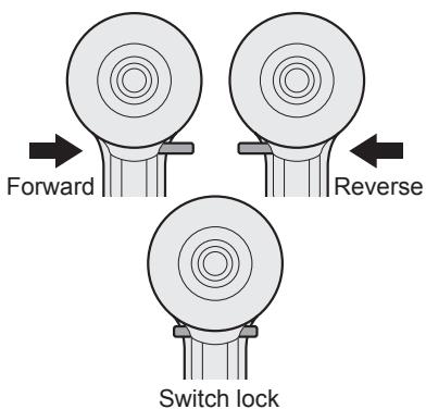
6) When storing or carrying the tool, set the Forward/Reverse lever to the center position (switch lock).
7) Do not strain the tool by holding the speed control trigger halfway (speed control mode) so that the motor stops.
| Symbol | Meaning |
| V | Volts |
| --- | Direct current |
| n0 | No load speed |
| ... min-1 | Revolutions or reciprocations per minutes |
| Ah | Electrical capacity of battery pack |
| Read the operating instructions before use. | |
| For indoor use only. | |
WARNING:
- Do not use other than the Panasonic battery packs that are designed for use with this rechargeable tool.
- Panasonic is not responsible for any damage or accident caused by the use of recycled or counterfeit battery pack.
- Do not dispose of the battery pack in a fire, or expose it to excessive heat.
- Do not drive the likes of nails into the battery pack, subject it to shocks, dismantle it, or attempt to modify it.
- Do not allow metal objects to touch the battery pack terminals.
- Do not carry or store the battery pack in the same container as nails or similar metal objects.
- Do not charge the battery pack in a high-temperature location, such as next to a fire or in direct sunlight. Otherwise, the battery may overheat, catch fire, or explode.
-
Never use other than the dedicated charger to charge the battery pack. Otherwise, the battery may leak, overheat, or explode.
-
After removing the battery pack from the tool or the charger, always reattach the pack cover. Otherwise, the battery contacts could be shorted, leading to a risk of fire.
- When the Battery Pack Has Deteriorated, Replace It with a New One. Continued use of a damaged battery pack may result in heat generation, ignition or battery rupture.
II. ASSEMBLY
Attaching or Removing Bit
NOTE:
-
When attaching or removing a bit, disconnect battery pack from tool or place the switch in the center position (switch lock).
-
Hold the collar of quick connect chuck and pull it out from the driver.
- Insert the bit into the chuck. Release the collar.
- The collar will return to its original position when it is released.
- Pull the bit to make sure it does not come out.
- To remove the bit, pull out the collar in the same way.
CAUTION:
- If the collar does not return to its original position or the bit comes out when pulled on, the bit has not been properly attached. Make sure the bit is properly attached before use.
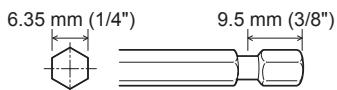
Use 6.35 mm (1/4") hexagonal bits.
To ensure proper securement of the bit, use only hexagonal bits with 9.5mm (3 / 8^ ) detent.
Attaching or Removing Socket
- Attaching Socket
Attach the socket by sliding the female detent on the bottom of the socket to the square drive on the body.
Make sure the socket is firmly connected to the body.
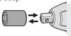
- Removing Socket
Pull out the socket.
NOTE:
Attaching or Removing Original Options and Sockets
Keep the body above freezing point (0^32^) when attach or detach original options and sockets to the square drive on the body. The cushion rubber in the square drive to push up the ball may get hard under freezing point. This requires extra force in detaching and attaching sockets.
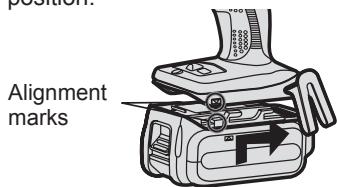
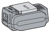
Attaching or Removing Battery Pack
- To connect the battery pack:
Line up the alignment marks and attach the battery pack.
- Slide the battery pack until it locks into position.
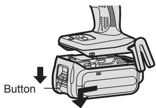
- To remove the battery pack:
Pull the button from the front to release the battery pack.
III. OPERATION
WARNING!
- Do not inhale any smoke emitted from the tool or battery pack as it may be harmful.
[Main Body]
Switch and Forward/Reverse Lever Operation
CAUTION:
To prevent damage, do not operate Forward/Reverse lever until the bit comes to a complete stop.
Forward Rotation Switch Operation
- Push the lever for forward rotation.
- Depress the trigger switch slightly to start the tool slowly.
- The speed increases with the amount of depression of the trigger for efficient tightening of screws. The brake operates and the bit stops immediately when the trigger is released.
- After use, set the lever to its center position (switch lock).
Reverse Rotation Switch Operation
- Push the lever for reverse rotation. Check the direction of rotation before use.
-
Depress the trigger switch slightly to start the tool slowly.
-
After use, set the lever to its center position (switch lock).
CAUTION:
- To eliminate excessive temperature increase of the tool surface, do not operate the tool continuously using two or more battery packs. Tool needs cool off time before switching to another pack.
How to Use the Belt Hook
WARNING!
- Be sure to attach the belt hook securely to the main unit with the screw firmly fastened. When the belt hook is not firmly attached to the main unit, the hook may disconnect and the main unit may fall. This may result in an accident or injury.
Periodically check screw for tightness. If found to be loose, tighten firmly. - Be sure to attach the belt hook firmly and securely onto a waist belt or other belt. Pay attention that the unit does not slip off the belt. This may result in an accident or injury.
- When the main unit is held by the belt hook, avoid jumping or running with it. Doing so may cause the hook to slip and the main unit may fall. This may result in an accident or injury.
- When the belt hook is not used, be sure to return it to the storing position. The belt hook may catch on something. This may result in an accident or injury.
- When the unit is hooked onto the waist belt by the belt hook, do not attach driver bits to the unit. A sharp edge object, such as a drill bit, may cause injury or an accident.
To Change the Belt Hook Location Side
The belt hook can be attached to either side of the unit.
- Removing the hook
(1) Remove the nut.
(2) Draw out the hook.
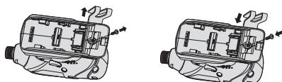
- Attaching the hook to the other side
(1) Insert the hook in the other side.
(2) Tighten the nut fully so that it securely fastened.
Control Panel
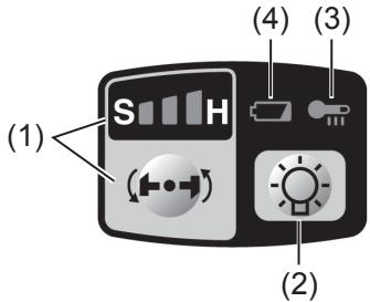
(1) Impact Power Mode Select
- Selecting the impact power among 3 modes (Soft, Medium, Hard).
Press the impact power mode button to set it. The mode changes to hard, medium, or soft each time the button is pressed.
The driver is preset to "hard" impact mode setting when shipped from the manufacturer.
Recommended work guideline table
| Impact Power mode Display | Recommended Application |
| 0-2300 r.p.m./0-2500 r.p.m.and0-3000 i.p.m./0-3300 i.p.m./0-3500 i.p.m. | Jobs requiring a high level of torque where there is no possibility of the bolts or screw breaking, its top shearing off, or the bit coming loose. (This setting provides maximum torque.) Suitable applications include:·Tightening M8 and larger bolts·Tightening long screws during interior finishing work |
| M0-1400 r.p.m.and0-2800 i.p.m. | Jobs requiring limited torque where there is a possibility of the screw breaking or its top shearing off. (This setting limits torque.) Suitable applications include:·Tightening bolts with smaller diameters (M6)·Tightening metalwork screws when installing fixtures |
| S0-1000 r.p.m.and0-2000 i.p.m. | Jobs requiring limited torque where there is a possibility of the screw breaking, its top shearing off, or the bit coming loose and damaging a finished exterior surface. (This setting limits torque.)Suitable applications include:·Tightening bolts smaller than M6 that may shear easily·Tightening screws into molded plastic·Installing gypsum wallboard |
- i.p.m. = Impact per minute.
Avoid repeatedly depressing the switch when the bolts and screws are securely fastened.
Not doing so may cause a delay in rotation starting, or the Impact Power mode display to flash and prevent rotation from starting for circuit protection.
(2) LED light
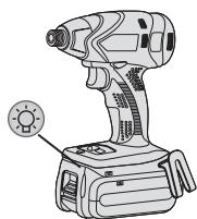
Pressing the button toggles the LED light on and off.
The light illuminates with very low current, and it does not adversely affect the performance of the driver during use or its battery capacity.
CAUTION:
- The built-in LED light is designed to illuminate the small work area temporarily.
- Do not use it as a substitute for a regular flashlight, since it does not have enough brightness.
Caution: DO NOT STARE INTO BEAM.
Use of controls or adjustments or performance of procedures other than those specified herein may result in hazardous radiation exposure.
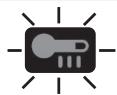
(3) Overheat warning lamp


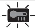
Off (normal operation)
Flashing: Overheat
Indicates operation has been halted due to motor or battery overheating.
The overheating protection feature halts driver operation to protect the motor and battery pack in the event of overheating. The overheat warning lamp on the control panel flashes when this feature is active.
- If the overheating protection feature activates, allow the driver to cool thoroughly (at least 30 minutes). The driver is ready for use when the overheat warning lamp goes out.
- Avoid using the driver in a way that causes the overheating protection feature to activate repeatedly.
(4) Battery low warning lamp

Off (normal operation)

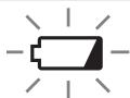
Flashing (No charge) Battery protection feature active
Excessive (complete) discharging of Li-ion batteries shortens their service life dramatically. The driver includes a battery protection feature designed to prevent excessive discharging of the battery pack.
- The battery protection feature activates immediately before the battery loses its charge, causing the battery low warning lamp to flash.
- If you notice the battery low warning lamp flashing, charge the battery pack immediately.
Recommended Grip
Use the grip to hold and operate the driver with one hand. If the job requires additional force, you can push against the rear end of the driver with your other hand.
[Battery Pack]
For Appropriate Use of Battery Pack
Li-ion Battery Pack
- For optimum battery life, store the Li-ion battery pack following use without charging it.
- When charging the battery pack, confirm that the terminals on the battery charger are free of foreign substances such as dust and water etc. Clean the terminals before charging the battery pack if any foreign substances are found on the terminals.
The life of the battery pack terminals may be affected by foreign substances such as dust and water etc. during operation.
- When battery pack is not in use, keep it away from other metal objects like: paper clips, coins, keys, nails, screws, or other small metal objects that can make a connection from one terminal to another.
Shorting the battery terminals together may cause sparks, burns or a fire.
- When operating the battery pack, make sure the work place is well ventilated.
- When the battery pack is removed from the main body of the tool, replace the battery pack cover immediately in order to prevent dust or dirt from contaminating the battery terminals and causing a short circuit.
Battery Pack Life
The rechargeable batteries have a limited life. If the operation time becomes extremely short after recharging, replace the battery pack with a new one.
[Battery Charger] Charging
CAUTION:
- If the temperature of the battery pack falls approximately below -10^ ( 14^ ), charging will automatically stop to prevent degradation of the battery.
- The ambient temperature range is between 0^ (32^) and 40^ (104^) .
If the battery pack is used when the battery temperature is below 0^ (32^) the tool may fail to function properly.
- When charging a cool battery pack (below 0^ ( 32^ ) in a warm place, leave the battery pack at the place and wait for more than one hour to warm up the battery to the level of the ambient temperature.
- Cool down the charger when charging more than two battery packs consecutively.
- Do not insert your fingers into contact hole, when holding charger or any other occasions.
To prevent the risk of fire or damage to the battery charger.
- Do not use power source from an engine generator.
- Do not cover vent holes on the charger and the battery pack.
- Unplug the charger when not in use.
NOTE:
Your battery pack is not fully charged at the time of purchase. Be sure to charge the battery before use.
Battery charger
- Plug the charger into the AC outlet.
- Insert the battery pack firmly into the charger.
1 Line up the alignment marks and place the battery onto the dock on the charger.
2 Slide forward in the direction of the arrow.
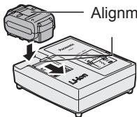
Alignment marks
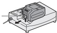
-
During charging, the charging lamp will be lit. When charging is completed, an internal electronic switch will automatically be triggered to prevent overcharging.
-
Charging will not start if the battery pack is warm (for example, immediately after heavy-duty operation).
The orange standby lamp will be flashing until the battery cools down.
Charging will then begin automatically.
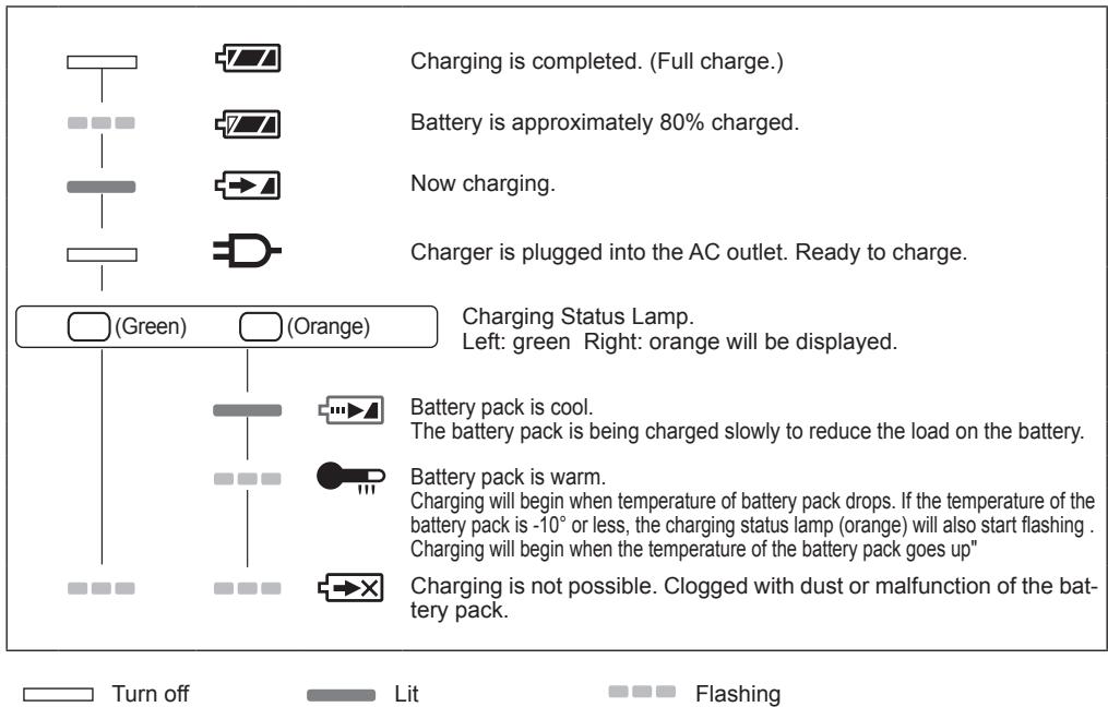
- The charge lamp (green) will flash slowly once the battery is approximately 80% charged.
- When charging is completed, the charging lamp in green color will turn off.
- If the temperature of the batter pack is 0^ or less, charging takes longer to fully charge the battery pack than the standard charging time.
Even when the battery is fully charged, it will have approximately 50% of the power of a fully charged battery at normal operating temperature.
- Consult an authorized dealer if the charging lamp (green) does not turn off.
- If a fully charged battery pack is inserted into the charger again, the charging lamp lights up. After several minutes, the charging lamp in green color will turn off.
- Remove the battery pack while the battery pack release button is held up.
Battery pack release button
LAMP INDICATIONS
Information for Users on Collection and Disposal of Old Equipment and used Batteries


Cd
These symbols on the products, packaging, and/or accompanying documents mean that used electrical and electronic products and batteries should not be mixed with general household waste.
For proper treatment, recovery and recycling of old products and used batteries, please take them to applicable collection points, in accordance with your national legislation and the Directives 2002/96/EC and 2006/66/EC.
By disposing of these products and batteries correctly, you will help to save valuable resources and prevent any potential negative effects on human health and the environment which could otherwise arise from inappropriate waste handling.
For more information about collection and recycling of old products and batteries, please contact your local municipality, your waste disposal service or the point of sale where you purchased the items.
Penalties may be applicable for incorrect disposal of this waste, in accordance with national legislation.
For business users in the European Union
If you wish to discard electrical and electronic equipment, please contact your dealer or supplier for further information.
[Information on Disposal in other Countries outside the European Union]
These symbols are only valid in the European Union. If you wish to discard these items, please contact your local authorities or dealer and ask for the correct method of disposal.
Note for the battery symbol (bottom two symbol examples):
This symbol might be used in combination with a chemical symbol. In this case it complies with the requirement set by the Directive for the chemical involved.
IV. MAINTENANCE
- Use only a dry, soft cloth for wiping the unit. Do not use a damp cloth, thinner, benzine, or other volatile solvents for cleaning.
- In the event that the inside of the tool or battery pack is exposed to water, drain and allow to dry as soon as possible. Carefully remove any dust or iron filings that collect inside the tool. If you experience any problems operating the tool, consult with a repair shop.
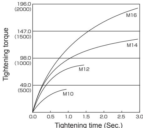
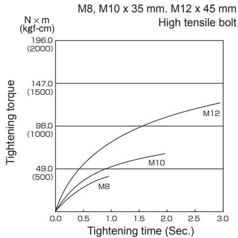
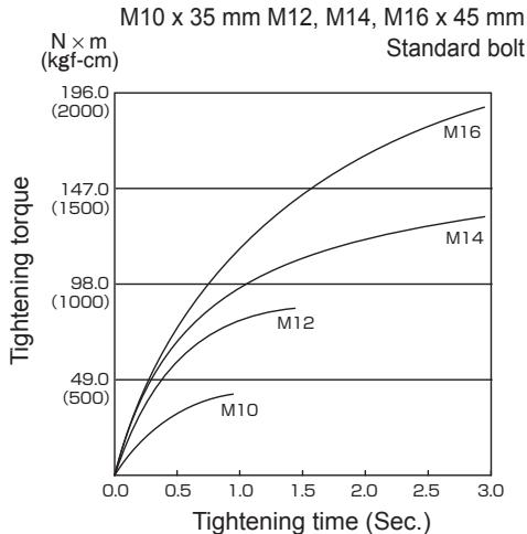
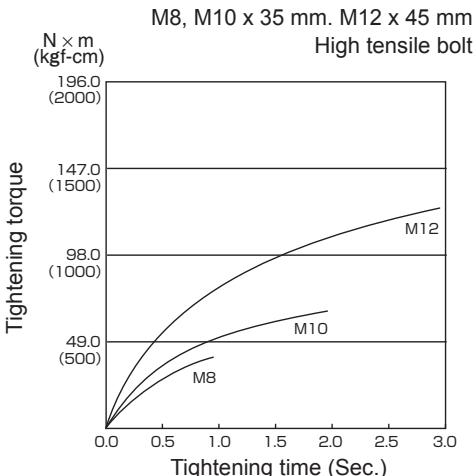
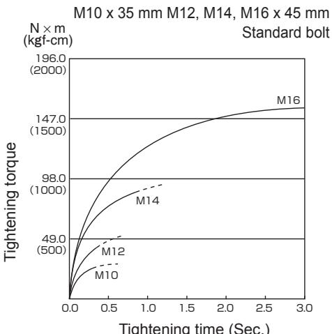
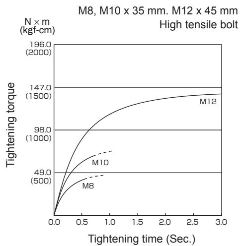
V. TIGHTENING TORQUE
The power required for tightening a bolt will vary, according to bolt material and size, as well as the material being bolted. Choose the length of tightening time accordingly.
Reference values are provided below.
(They may vary according to tightening conditions.)
Factors Affecting Tightening Torque
The tightening torque is affected by a wide
variety of factors including the followings. After tightening, always check the torque with a torque wrench.
1) Voltage
When the battery pack becomes nearly discharged, the voltage decreases and the tightening torque drops.
Bolt Tightening Conditions
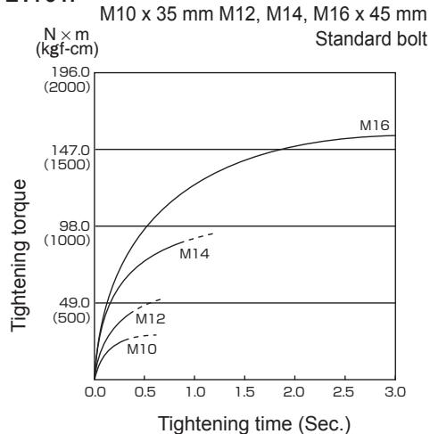
EY7546
M10 x 35 mm M12, M14, M16 x 45 mm
Standard bolt
N×m (kgf-cm)
EY7546
EY7547
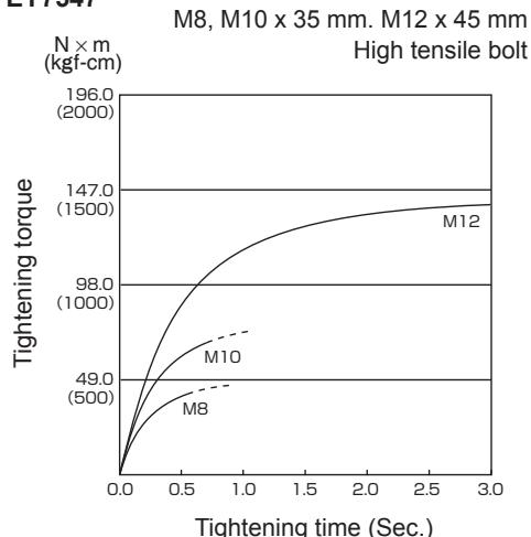
EY7547
EY7550
EY7550
EY7551
EY7551
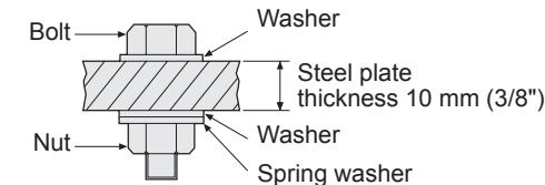
Tightening conditions
- The following bolts are used.
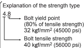
Standard bolts: Strength type 4.8
High tensile type 12.9
2) Tightening time
Longer tightening time results in increased tightening torque. Excessive tightening, however, adds no value and reduces the life of the tool.
3) Different bolt diameters
The size of the bolt diameter affects the tightening torque.
Generally, as the bolt diameter increases, tightening torque rises.
4) Tightening conditions
- Tightening torque will vary, even with the same bolt, according to grade, length, and torque coefficient (the fixed coefficient indicated by the manufacturer upon production).
- Tightening torque will vary, even with the same bolting material (e.g. steel), according to the surface finish.
- Torque is greatly reduced when the bolt and nut start turning together.
5) Socket play
Torque is lowered as the six-sided configuration of the socket of the wrong size is used to tighten a bolt.
6) Switch (Variable speed control trigger)
Torque is lowered if the unit is used with the switch not fully depressed.
7) Effect of Connecting Adaptor
The tightening torque will be lowered through the use of a universal joint or a connecting adaptor.
VI. ACCESSORIES
Use only suitable size of bit.
Panasonic original Optional Quick change chuck (EY9HX110E).
Chuck Size: 6.35 mm (1/4") hex
VII. APPENDIX
MAXIMUM RECOMMENDED CAPACITIES
| Model | EY7546 | EY7547 | EY7550 | EY7551 | |
| Screw driving | Wood screw | φ 3.5 mm - φ 9.5 mm | |||
| Self-drilling screw | φ 3.5 mm - φ 6 mm | ||||
| Bolt fastening | Standard bolt:M6-M16 High tensile bolt: M6 - M12 | ||||
VIII. SPECIFICATIONS
MAIN UNIT
| Model | EY7546 | EY7547 | EY7550 | EY7551 | |
| Motor voltage | 14.4 V | 18 V | |||
| No load speed | soft mode | 0 - 1000 min-1(rpm) | |||
| medium mode | 0 - 1400 min-1(rpm) | ||||
| hard mode | 0 - 2500 min-1(rpm) | 0 - 2300 min-1(rpm) | 0 - 2500 min-1(rpm) | 0 - 2300 min-1(rpm) | |
| Maximum torque | 150 N·m (1330 in.lbs) | 200 N·m (1770 in.lbs) | 155 N·m (1370 in.lbs) | 205 N·m (1815 in.lbs) | |
| Impact per minute | soft mode | 0 - 2000 min-1(rpm) | |||
| medium mode | 0 - 2800 min-1(rpm) | ||||
| hard mode | 0 - 3000 min-1(rpm) | 0 - 3500 min-1(rpm) | 0 - 3300 min-1(rpm) | 0 - 3500 min-1(rpm) | |
| Overall length | 143 mm (5-5/8") | 155 mm (6-1/8") | 143 mm (5-5/8") | 155 mm (6-1/8") | |
| Weight (with battery pack EY9L44) | 1.5 kg (3.3lbs) | 1.55 kg (3.4lbs) | — | — | |
| Weight (with battery pack EY9L50) | — | — | 1.6 kg (3.5lbs) | 1.65 kg (3.6lbs) | |
BATTERY PACK
| Model | EY9L41 | EY9L42 | EY9L44 | EY9L50 |
| Storage battery | Li-ion | |||
| Battery voltage | 14.4 V DC (3.6 V x 4 cells) | 14.4 V DC (3.6 V x 8 cells) | 18 V DC (3.6 V x 10 cells) | |
BATTERY CHARGER
| Model | EY0L81 | |||
| Electrical rating | See the rating plate on the bottom of the charger. | |||
| Charging time | EY9L41 | EY9L42 | EY9L44 | EY9L50 |
| Usable: 45 min. | Usable: 30 min. | Usable: 50 min. | ||
| Full: 60 min. | Full: 35 min. | Full: 65 min. | ||
NOTE: This chart may include models that are not available in your area.
Please refer to the latest general catalogue.
For the dealer name and address, please see the included warranty card.
ONLY FOR U. K.
IX. ELECTRICAL PLUG INFORMATION
FOR YOUR SAFETY PLEASE READ THE FOLLOWING TEXT CAREFULLY
This appliance is supplied with a moulded three pin mains plug for your safety and convenience.
A 5 amp fuse is fitted in this plug.
Should the fuse need to be replaced please ensure that the replacement fuse has a rating of 5 amp and that it is approved by ASTA or BSI to BS1362.
Check for the ASTA mark or the BSI mark on the body of the fuse.
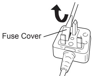
If the plug contains a removable fuse cover you must ensure that it is refitted when the fuse is replaced.
If you lose the fuse cover the plug must not be used until a replacement cover is obtained.
A replacement fuse cover can be purchased from your local Panasonic Dealer.
IF THE FITTED MOULDED PLUG IS UNSUITABLE FOR THE SOCKET OUTLET IN YOUR HOME THEN THE FUSE SHOULD BE REMOVED AND THE PLUG CUT OFF AND DISPOSED OF SAFELY.
THERE IS A DANGER OF SEVERE ELECTRICAL SHOCK IF THE CUT OFF PLUG IS INSERTED INTO ANY 13 AMP SOCKET.
If a new plug is to be fitted please observe the wiring code as shown below.
If in any doubt please consult a qualified electrician.
IMPORTANT:
The wires in this mains lead are coloured in accordance with the following code:
Blue: Neutral
Brown: Live
As the colours of the wire in the mains lead of this appliance may not correspond with the coloured markings identifying the terminals in your plug, proceed as follows.
The wire which is coloured BLUE must be connected to the terminal in the plug which is marked with the letter N or coloured BLACK.
The wire which is coloured BROWN must be connected to the terminal in the plug which is marked with the letter L or coloured RED.
Under no circumstances should either of these wires be connected to the earth terminal of the three pin plug, marked with the letter E or the Earth Symbol 1÷ .
How to replace the fuse: Open the fuse compartment with a screwdriver and replace the fuse and fuse cover if it is removable.
This apparatus was produced to BS800.
(3) Varsellampe for overoppheting

Av (normalt arbeit)


m = 311 ;


Cd
VIII. TEKNISET TIEDOT
PÄALAITE
EN. GR. FR. IT. ND. ES. DN. SW. NR. FN.
EY971075501 2011.03
Printed in China