EY6903 - Cordless drill PANASONIC - Free user manual and instructions
Find the device manual for free EY6903 PANASONIC in PDF.
| Product type | Cordless impact drill/driver |
| Brand | Panasonic |
| Model | EY6903 |
| Overall length | 236 mm |
| Weight (with battery) | 2.2 kg |
| Power supply | Ni-MH battery 12 V DC (1.2 V x 10 cells) |
| Drilling capacity - Mortar/Brick | Ø 3 ~ Ø 10 mm |
| Drilling capacity - Wood | Ø 3 ~ Ø 25 mm |
| Drilling capacity - Metal | Ø 1.5 ~ Ø 13 mm |
| Screwing capacity - Machine screws | M3 ~ M5 |
| Screwing capacity - Wood screws | Ø 2.1 ~ Ø 5.8 mm |
| Maximum torque (low speed) | 17.8 Nm |
| No-load speed - Low speed | 80 ~ 550 rpm |
| No-load speed - High speed | 300 ~ 2000 rpm |
| Impact rate - Low speed | 1200 ~ 8250 impacts/min |
| Chuck capacity | Ø 1.5 ~ Ø 13 mm (keyless) |
| Clutch torque settings | 5 positions + hammer |
| Safety | Switch lock, motor brake, overload protection |
| Maintenance and cleaning | Clean with a dry cloth, do not use water or solvents |
| Recommended charging temperature | 0 °C ~ 40 °C |
| Compatible charger | EY0110 |
| Compatible batteries | EY9200, EY9201, EY9230, EY9231 |
Frequently Asked Questions - EY6903 PANASONIC
User questions about EY6903 PANASONIC
0 question about this device. Answer the ones you know or ask your own.
Ask a new question about this device
Download the instructions for your Cordless drill in PDF format for free! Find your manual EY6903 - PANASONIC and take your electronic device back in hand. On this page are published all the documents necessary for the use of your device. EY6903 by PANASONIC.
USER MANUAL EY6903 PANASONIC
Cordless Hammer Drill & Driver
Before operating this unit, please read these instructions completely and save this manual for future use.
Read the Safety Instructions booklet and the following before using.
I. ADDITIONAL SAFETY RULES
1) Be aware that this tool is always in an operating condition, since it does not have to be plugged into an electrical outlet.
2) When drilling or driving into walls, floors, etc., "live" electrical wires may be encountered. DO NOT TOUCH THE CHUCK OR ANY FRONT METAL PARTS OF THE TOOL! Hold the tool only by the plastic handle to prevent electric shock in case you drill or drive into a "live" wire.
3) If the bit becomes jammed, immediately turn the main switch off to prevent an overload, which can damage the battery pack or motor. Use reverse motion to loosen jammed bits.
4) Do NOT operate the Forward/Reverse lever when the main switch is on. The battery will discharge rapidly and damage to the unit may occur.
5) During charging, the charger may become slightly warm. This is normal. Do NOT charge the battery for a long period.
6) Use only a dry, soft cloth to wipe the unit. Do NOT use a damp cloth, thinner, benzine, or other volatile solvents for cleaning.
7) When storing or carrying the tool, set the Forward/Reverse lever to the center position (switch lock).
8) Do not strain the tool by holding the speed control trigger halfway (speed control mode) so that the motor stops.
9) Wear ear protectors when using the tool for extended periods.
10) The appliance is not intended for use by young children or infirm persons without supervision.
11) Young children should be supervised to ensure that they do not play with the appliance.
II. ASSEMBLY Attaching or removing bit
Note:
When attaching or removing a bit,
disconnect battery pack from tool or place the switch in the center position (switch lock).
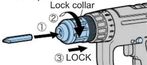
This tool is equipped with a keyless drill chuck.
- Attachment
Insert the bit and turn the Lock collar clockwise (looking from the front) to tighten firmly.
Slide the Lock collar to LOCK side until it snaps.
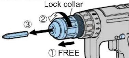
- Removal
Slide the Lock collar to FREE side.
Turn the Lock collar counterclockwise (looking from the front), then remove the bit.
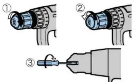
Note:
If excessive play occurs in the chuck, ① secure the drill in place and tighten the chuck by turning clockwise, ② open the chuck jaws by unscrewing the Lock collar and ③ tighten the screw (left-handed screw) with a screwdriver by turning it counterclockwise (viewed from the front).
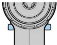
Attaching or removing battery pack
-
To connect the battery pack: Insert the battery pack. It snaps into place to indicate proper connection.
-
To remove the battery pack:
Press the two buttons on the sides of the battery pack. Slide the battery pack out of the tool body.
III. OPERATION
Switch Operation
- The speed increases with the amount of depression of the trigger. When beginning work, depress the trigger slightly to start the rotation slowly.
- A feedback electronic controller is used to give a strong torque even in low speed.
- The brake operates when the trigger is released and the motor stops immediately.
Note:
When the brake operates, a braking sound may be heard. This is normal.
Forward/Reverse lever operation
(Forward , Switch lock, Reverse ())
CAUTION:
Do not operate Forward/Reverse lever until the chuck comes to a complete stop. Shifting during rotation of the chuck may damage the tool.
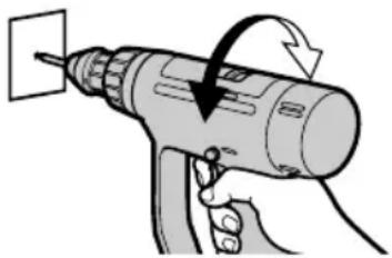
Forward Rotation Switch Operation
- For forward rotation, set the lever to forward.
- Depress the trigger switch slightly to start the tool slowly.
- The speed increases with the amount of depression of the trigger for efficient tightening of screws and drilling. The brake operates and the chuck stops immediately when the trigger is released.
- After use, set the lever to its center position (switch lock).
Reverse Rotation Switch Operation
- For reverse rotation, set the lever to reverse. Check the direction of rotation before use.
- Depress the trigger switch slightly to start the tool slowly.
- After use, set the lever to its center position (switch lock).
Clutch Torque Setting
Adjust the torque to one of the 5 possible settings or "2", "position to the job.
CAUTION:
Test the setting before actual operation.
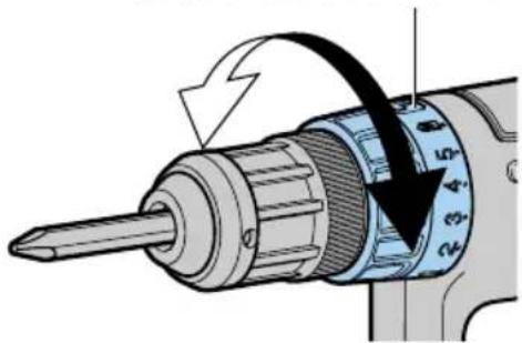
Set the scale at this line.
Reference for Adjusting Torque
| Scale | Torque Use | |
| 1 | Approx. 1.0 Nm(10 kgf-cm or 8.7 in-lbs.) | For driving terminal screws |
| 2 | Approx. 1.5 Nm(15 kgf-cm or 13.0 in-lbs.) | For driving machine screws |
| 3 | Approx. 2.5 Nm(25 kgf-cm or 21.7 in-lbs.) | For driving screws into soft materials |
| 4 | Approx. 3.4 Nm(35 kgf-cm or 30.5 in-lbs.) | For driving screws into hardwood |
| 5 | Approx. 4.4 Nm(45 kgf-cm or 39.0 in-lbs.) | |
| 2 | EY6903:17.8 Nm (182 kgf-cm, 158 in-lbs.) (Low speed) | For powerful driving and drilling |
| EY6932:25.5 Nm (260 kgf-cm, 225 in-lbs.) (Low speed) | ||
| Percussion | For drilling to mortar, brick, etc. |
Bit-locking function
- With the trigger switch not engaged and a screwdriver bit locked in place, the tool can be used as a manual screwdriver (up to 22.6 Nm, 230 kgf-cm, 199 in-lbs).
There will be a little play in the chuck, but this is not a malfunction.
- This feature is handy for tightening screws that require more torque than the maximum torque of the driver (position on the clutch), for confirming the tightness of a screw or to loosen an extremely tight screw.
Speed Selection
Choose a low or high speed to suit the use.
The more the speed control trigger is pulled, the higher the speed becomes.
| No load speed Torque | |
| LOW | 80 - 550/min (rpm) Strong |
| HIGH | 300 - 2000/min (rpm) Weak |
CAUTION:
- Check the speed selector switch before use.
- Use at low speed when strong force is needed during operation. (Using at high speed while a strong force is applied may cause a motor breakdown.)
- Do not operate the speed selector switch (LOW-HIGH) while pulling on the speed control trigger. This can cause the rechargeable battery to wear quickly or damage the internal mechanism of the motor.
- See appendix for "RECOMMENDED SPEED SELECTION".
For Appropriate use of Battery pack
Ni-MH Battery pack (EY9200/EY9201/EY9230/EY9231)
Charge the Ni-MH battery fully before storage in order to ensure a longer service life.
The ambient temperature range is between 0^ (32^) and 40^ (104^) .
If the battery pack is used when the battery temperature is below 0^ (32^) , the tool may fail to function properly. In that case, charge the battery until charging is completed for appropriate functioning of the battery.
When battery pack is not in use, keep it away from other metal objects like: paper clips, coins, keys, nails, screws, or other small metal objects that can make a connection from one terminal to another.
Shorting the battery terminals together may cause sparks, burns or a fire.
When operating with a Ni-MH battery pack, make sure the place is well-ventilated.
Battery Pack Life
The rechargeable batteries have a limited life. If operation time becomes extremely short after recharging, replace the battery pack with a new one.
Note:
Use under extremely hot or cold conditions will reduce operating capacity per charge.
Battery Recycling
ATTENTION:
For environmental protection and recycling of materials, be sure that it is disposed of at an officially assigned location, if there is one in your country.
Charging
Note:
When you charge the battery pack for the first time, or after prolonged storage, charge it for about 24 hours to bring the batteries up to full capacity.
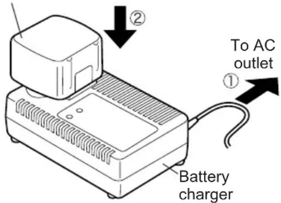
Battery charger (EY0110)
- Plug the charger into the AC outlet.
Note:
Sparks may be produced when the plug is inserted into the AC power supply, but this is not a problem in terms of safety.
- Insert the battery pack firmly into the charger.
Battry pack
- During charging, the charging lamp will be lit.
When charging is completed, an internal electronic switch will automatically be triggered to prevent overcharging.
- Charging will not start if the battery pack is warm (for example, immediately after heavy-duty operation).
The orange standby lamp will be lit until the battery cools down. Charging will then begin automatically.
- When charging is completed, the charging lamp will start flashing quickly in green color.
- When in any of the conditions that battery pack is too cool, or the bat -
tery pack has not been used for a long time, the charging lamp is lit. In this case charging takes longer to fully charge the battery pack, than the standard charging time.
-
If a fully charged battery pack is inserted into the charger again, the charging lamp light up. After several minutes, the charging lamp may flash quickly to indicate the charging is completed.
-
If the charging lamp does not light immediately after the charger is plugged in, or if after the standard charging time the lamp does not go off, consult an authorized dealer.
Note:
- When charging a cool battery pack (below 5^ (41^) ) in a warm place, leave the battery pack at the place and wait for more than one hour to warm up the battery to the level of the ambient temperature. Otherwise battery pack may not be fully charged.
Cool down the charger when charging more than two battery packs consecutively. - Do not insert your fingers into contact hole, when holding charger or any other occasions.
CAUTION:
- Do not use power source from an engine generator.
- Do not cover vent holes on the charger and the battery pack
- Unplug the charger when not in use.
IV. LAMP INDICATIONS
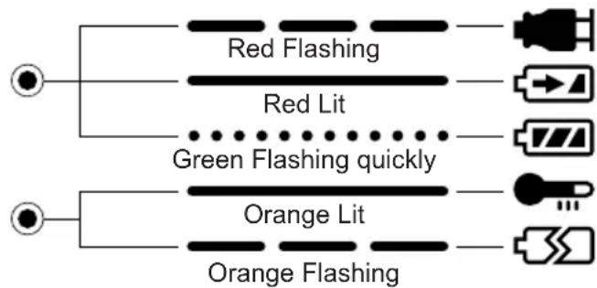
Charger is plugged into the AC outlet. Ready to charge.
Now charging
Charging is completed.
Battery pack is warm. Charging will begin when temperature of battery pack drops.
Charging is not possible. Clogged with dust or malfunction of the battery pack.
V. ACCESSORIES
Use only bits suitable for size of drill's chuck.
VI. APPENDIX
RECOMMENDED SPEED SELECTION
CAUTION:
- USE AT LOW SPEED WHEN STRONG FORCE IS NEEDED DURING OPERATION.
(Using at high speed while a strong force is applied may cause a motor breakdown.)
- Use the following as a guide to select low or high speed for the job.
EY6903
| DRILLING | SCREW TIGHTENING | ||||
| MATERIAL/ CONDITION | MORTAR / BRICK | WOOD / YELLOW PINE | METAL METAL | HOLE SAW | Wood screws |
| Thickness: 40 mm (1-37/64") or less | Cold-rolled steel plate (SPC) Thickness: 1.6 mm (1/16") or less | ||||
| HIGH ø 10 mm (3/8") or less Not used | ø 4.5 mm (11/64") or less | Not used | ø 3.5 mm (9/64") or less | ||
| LOW | ø 10 mm (3/8") or less(Slow operation) | ø 25 mm (63/64") or less | ø 13 mm (1/2") or less | ø 26 mm (1-1/64") or less | ø 6 mm (15/64") or less |
EY6932
| DRILLING | SCREW TIGHTENING | ||||
| MATERIAL/ CONDITION | MORTAR / BRICK | WOOD / YELLOW PINE | METAL METAL | HOLE SAW | Wood screws |
| Thickness: 40 mm (1-37/64") or less | Cold-rolled steel plate (SPC) Thickness: 1.6 mm (1/16") or less | ||||
| HIGH ø 10 mm (3/8") or less Not used | ø 6.5 mm (1/4") or less | Not used | ø 4 mm (5/32") or less | ||
| LOW | ø 13 mm (1/2") or less (Slow operation) | ø 36 mm (1-27/64") or less | ø 13 mm (1/2") or less | ø 34 mm (1-11/32") or less | ø 6.8 mm (17/64") or less |
VII. SPECIFICATIONS
MAIN UNIT
| Model EY6903 EY6932 | ||||
| Capability | Screw driving | Machine screw M3 | - M5 M3 - M6 | |
| Wood screw | Ø 2.1 - Ø 5.8 mm (5/64" - 15/64") | Ø 2.1 - Ø 6.8 mm (5/64" - 17/64") | ||
| Masonry screw Ø 4 | - Ø 6 mm (5/32" - 15/64") | |||
| Drilling | Mortar/Brick Ø 3 - Ø | 10 mm (1/8" - 3/8") Ø 3 - Ø 13 mm (1/8" - 1/2") | ||
| Wood Ø 3 - Ø 25 mm | (1/8" - 63/64") Ø 3 - Ø 36 mm (1/8" - 1/27/64") | |||
| Metal Ø 1.5 - Ø 13 mm | mm (1/16" - 1/2") | |||
| Metal hole saw | Max. Ø 26 mm (1-1/64") | Max. Ø 34 mm (1-11/32") | ||
| Motor | DC Motor 12 V | DC Motor 15.6 V | ||
| No load speed | LOW | 80 - 550/min (rpm) | ||
| HIGH | 300 - 2000/min (rpm) | |||
| Blows rate per minute | LOW | 1200 - 8250/min (bpm) | ||
| HIGH | 4500 - 30000/min (bpm) | |||
| Chuck capacity | Ø 1.5 - Ø 13 mm (1/16" - 1/2") | |||
| Maximum torque | LOW | 17.8 Nm (182 kgf-cm or 158 in-lbs) | 25.5 Nm (260 k gf-cm or 225 in-lbs) | |
| HIGH | 4.6 Nm (47 kgf-cm or 41 in-lbs) | 5.9 Nm (60gf-cm or 52 in-lbs) | ||
| Blow strength | 1.7 kN (173 kgf, 370 lbs.f) | |||
| Overall length | 236 mm (9-5/16") | |||
| Weight (with battery pack) | 2.2 kg (4.9 lbs) | 2.4 kg (5.3 lbs) | ||
BATTERY PACK
| Model | EY9200 | EY9201 | EY9230 | EY9231 |
| Storage battery | Ni-MH Battery | |||
| Battery voltage | 12 V DC (1.2 V × 10 cells) | 15.6 V DC (1.2 V × 13 cells) | ||
BATTERY CHARGER
| Model | EY0110 | ||||||
| Electrical rating | See the rating plate on the bottom of the charger. | ||||||
| Weight | 0.78 kg (1.72 lbs) | ||||||
| Charging time | 7.2V | 9.6 V | 12V | 15.6V | 18V | 24V | |
| 1.2Ah | EY9065 | EY9080 | EY9001 | ||||
| EY9066 | EY9086 | EY9006 | |||||
| 20min. | |||||||
| 1.7Ah | EY9180 | EY9101 | |||||
| EY9182 | |||||||
| 25min. | |||||||
| 2.0Ah | EY9168 | EY9106 | EY9136 | EY9117 | |||
| 30min. | 30min. | 60min. | |||||
| 3.0Ah | EY9200 | EY9230 | EY9210 | ||||
| 45min. | 90min. | ||||||
| 3.5Ah | EY9201 | EY9231 | EY9251 | ||||
| 55min. | 65min. | ||||||
Note: This chart may include models that are not available in your area. Please refer to the catalogue.
ONLY FOR U.K.
VIII. ELECTRICAL PLUG INFORMATION
FOR YOUR SAFETY PLEASE READ THE FOLLOWING TEXT CAREFULLY
This appliance is supplied with a moulded three pin mains plug for your safety and convenience.
A 3 amp fuse is fitted in this plug.
Should the fuse need to be replaced please ensure that the replacement fuse has a rating of 3 amp and that it is approved by ASTA or BSI to BS1362.
Check for the ASTA mark or the BSI mark on the body of the fuse.
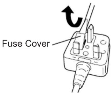
If the plug contains a removable fuse cover you must ensure that it is refitted when the fuse is replaced.
If you lose the fuse cover the plug must not be used until a replacement cover is obtained.
A replacement fuse cover can be purchased from your local Panasonic Dealer. IF THE FITTED MOULDED PLUG IS UNSUITABLE FOR THE SOCKET OUT - LET IN YOUR HOME THEN THE FUSE SHOULD BE REMOVED AND THE PLUG CUT OFF AND DISPOSED OF SAFELY. THERE IS A DANGER OF SEVERE ELECTRICAL SHOCK IF THE CUT OFF PLUG IS INSERTED INTO ANY 13 AMP SOCKET.
If a new plug is to be fitted please observe the wiring code as shown below.
If in any doubt please consult a qualified electrician.
IMPORTANT:
The wires in this mains lead are coloured in accordance with the following code:
Blue:Neutral
Brown:Live
As the colours of the wire in the mains lead of this appliance may not correspond with the coloured markings identifying the terminals in your plug, proceed as follows.
The wire which is coloured BLUE must be connected to the terminal in the plug which is marked with the letter N or coloured BLACK.
The wire which is coloured BROWN must be connected to the terminal in the plug which is marked with the letter L or coloured RED.
Under no circumstances should either of these wires be connected to the earth terminal of the three pin plug, marked with the letter E or the Earth Symbol 1一
How to replace the fuse: Open the fuse compartment with a screwdriver and replace the fuse and fuse cover if it is removable.
This apparatus was produced to BS800.
—MEMO —
- Para guitar las brocas
(Eteenpain, Kytkinlukko, Taaksepain)) HUOMAUTUS:
Matsushita Electric Works, Ltd.
Osaka, Japan