TYCE42PS20 - TV PANASONIC - Free user manual and instructions
Find the device manual for free TYCE42PS20 PANASONIC in PDF.
| Product type | Ceiling mount bracket for plasma screen |
| Brand | Panasonic |
| Model | TYCE42PS20 |
| Compatibility | Panasonic plasma screens (models listed on pages 96-97 of the manual) |
| Bracket weight | Approximately 16 kg |
| Maximum supported load | Depends on the screen weight (refer to the screen manual) |
| Material | Coated steel |
| Tilt angle | 0° to 30° in 5° increments |
| Directional adjustment | Horizontal (left-right orientation) |
| Ceiling attachment | 8 attachment points, M12 bolts (not included) |
| Operating ambient temperature | Up to 40°C |
| Maintenance and cleaning | Wipe with a soft dry cloth (cotton or flannel). For stubborn stains, use a diluted mild detergent then dry. Do not use gasoline, thinner, or wax. |
| Safety | Installation must be done by a professional. Check the ceiling's strength and use suitable components. Do not mount the screen facing upward or sideways. Leave a space of 10 cm around and 7 cm at the back. |
| Spare parts and repairability | The provided parts are specific. If lost, contact Panasonic. Do not modify the bracket. |
| General information | This bracket is designed exclusively for Panasonic plasma screens. Improper installation can result in serious injury or death. |
Frequently Asked Questions - TYCE42PS20 PANASONIC
User questions about TYCE42PS20 PANASONIC
0 question about this device. Answer the ones you know or ask your own.
Ask a new question about this device
Download the instructions for your TV in PDF format for free! Find your manual TYCE42PS20 - PANASONIC and take your electronic device back in hand. On this page are published all the documents necessary for the use of your device. TYCE42PS20 by PANASONIC.
USER MANUAL TYCE42PS20 PANASONIC
Fitting work and connection equipment expansion and removal should never be done by any other than a qualified installation specialist.
- Incorrect fitting may cause equipment to fall, resulting in injury.
Include a safety factor when considering the strength of the proposed fitting location. - If strength is not sufficient the equipment may fall, resulting in injury.
Do not fit at a location that cannot bear the load. - If the fitting location lacks sufficient strength the equipment may fall.
Ensure that the installation location is strong enough to support long-term use. - If its strength becomes insufficient over the course of long-term use, the plasma display may drop, possibly causing injury.
Do not disassemble or modify the ceiling-hanging bracket. - Otherwise the unit may be dropped and become damaged, and personal injury may result.
Take steps to prevent the ceiling-hanging bracket from falling. - Failure to carry out the installation completely may result in injury or even death.
CAUTION
Do not use any plasma displays other than those given in the catalogue.
- Otherwise the unit may be dropped and become damaged, and personal injury may result.
Do not fit at any locations subject to humidity, dust, smoke, steam or heat.
- This may have an adverse effect on the plasma display and cause fire or electric shock.
Do not fit facing upwards, sideways or upside down.
- This may cause heat to build up inside the plasma display, resulting in a fire.
Do not hang from or hang objects on the plasma display or ceiling-hanging bracket.
- The plasma display may fall and cause injury.
Do not block the ventilation holes. Do not block the space around the plasma display when using the ceiling-hanging bracket.
- Otherwise heat may build up inside and cause a fire.
When assembling and installing the ceiling-hanging bracket, make sure that the screws in all the locations are tightened up securely.
- Improper assembly may lead to insufficient strength, with the display falling over resulting in breakage and injury.
Secure at least 10 cm (3.9 inches) of space at the top, bottom, left, and right of the plasma display. Also secure at least 7 cm (2.8 inches) of space at the back.
- Failing to do so may result in a fire.
The work of fitting or removing the plasma display must be performed by at least two people.
- The plasma display may fall and cause injury.
For installation, use the special-purpose constituent parts.
- Otherwise, the plasma display may fall off the ceiling and/or be damaged, possibly causing injury.
Install the mounting screws and power cable in such a way that they will not make contact with the inside parts of the ceiling.
- Electric shocks may result from contact with any metal objects inside the ceiling.
When removing the plasma display, remove the ceiling-hanging brackets as well.
- Otherwise the unit may be dropped and become damaged, and personal injury may result.
Requests regarding handling
1) Exercise care when selecting the location for the plasma display because it may discolor or deform due to light or heat if it is placed where it is exposed to direct sunlight, or near a heater.
2) For cleaning, wipe the display using a soft dry cloth (made of cotton or flannel). If the unit is extremely soiled, first wipe off soiling with a neutral detergent diluted in water, and then wipe with a dry cloth. Do not use cleaners such as benzene, thinner or furniture wax because they may cause paint peeling.
(For information on cleaning the plasma display, see the plasma display's instruction manual. If using a chemically-treated cloth, follow the instructions supplied with the cloth.)
3) Do not affix adhesive tape or stickers to the product. Doing so may dirty the surface of the ceiling-hanging bracket. Do not allow long-term contact with rubber, vinyl products or the like. (Doing so will cause deterioration.)
4) The panel of the plasma display is glass. Do not subject it to a strong force or impact.
Caution:
This bracket is intended for only Panasonic plasma display models (See page 96-97).
Use with other apparatus is capable of resulting in instability causing possible injury.
PROFESSIONAL INSTALLATION IS REQUIRED.
PANASONIC DISCLAIMS ANY PROPERTY DAMAGE AND/OR SERIOUS INJURY, INCLUDING DEATH
RESULTING FROM IMPROPER INSTALLATION OR INCORRECT HANDLING.
Check that all the parts are accounted for and present in their designated quantities.
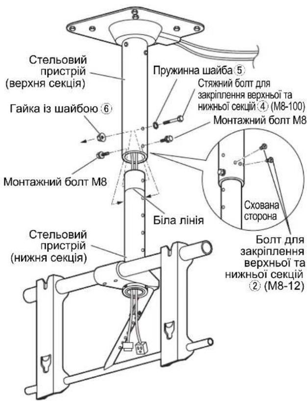
| ① Ceiling unit (1) | ② Bolt for fixing upper and lower sections (2) M8 × 12 | ③ Screw for securing unit (2) M5 × 35 | ||
| ④ Through bolt for fixing upper and lower sections (1) M8 × 100 | ⑤ Spring washer (1) M8 | ⑥ Washer pan nut (1) M8 | ||
| ⑦ Allen head countersunk screw (4) M8 × 32 | ⑧ Dished toothed washer (4) | ⑨ Insulation spacer (4) | ⑩ Ceiling cover (1) | |
| ⑪ Truss tapping screw (3) | ⑫ Rotation stop screw (1) M6 × 8 Spring washer (1) M6 | ⑬ Allen wrench (included tool) (1) | ⑭ Clampers (2) | |
[The images shown in this manual are for illustrative purpose only.]
Precautions for ceiling-hanging bracket fitting
This equipment is a ceiling unit to suspend the Plasma Display from a ceiling structure for viewing purposes. The ceiling unit must not be installed in any locations other than ceiling structures with sufficient strength.
To ensure correct plasma display performance and prevent trouble, do not fit at any of the following locations.
Near sprinklers or fire/smoke detectors
- Where there is a risk of exposure to vibration or impact
Near high-voltage wires or dynamic power supplies
- Near sources of magnetism, heat, water vapor or soot
- Locations exposed to air blown from heating equipment
- Where droplets of condensation from an air conditioner or other unit may form
Fit using techniques suited to the structure and materials of the fitting location.
When installing the ceiling unit to a ceiling structure, use structural components appropriate to the material of the structure, and an installation method.
Ensure good air flow so that the ambient temperature does not exceed 40^ (104^)
Failure to do this may cause heat to build up inside the plasma display, resulting in malfunction.
Spread a soft blanket or cloth over the floor so that the plasma display and floor will not be marked or scratched during the assembly and installation work.
When screwing down the parts, ensure that the screws are neither insufficiently tightened nor over tightened.
Take sufficient care and ensure safety around you when performing the installation work.
Do not install the plasma display underneath ceiling lamps (spotlights, halogen lamps, etc.). Otherwise, the cabinet may be bent or damaged by high heat.
1. Checking the strength of the installation location
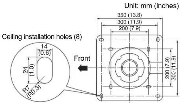
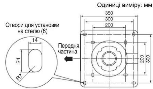
① The ceiling-hanging bracket weighs approximately 16kg (35.3 lbs).
Refer to the instruction manual of the plasma display, and check the weight of the plasma display unit which will be fitted into the ceiling-hanging bracket.
Refer to the outline drawing of the ceiling-hanging bracket shown on the right, and check the ceiling strength at the eight installation positions shown. If the strength at any of these positions is lacking, provide sufficient reinforcement.
2. Prepare the ceiling unit
① Remove the protective sheets (8 sheets) for the bracket of the ceiling unit at four locations.
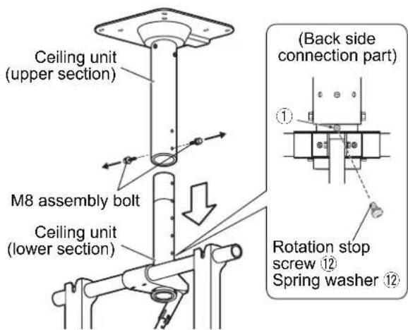
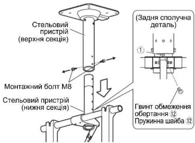
② Set a spring washer on the rotation stop screw ⑫, and fix at the position show on the right. (Tightening torque: 1.5 to 1.8 N·m)
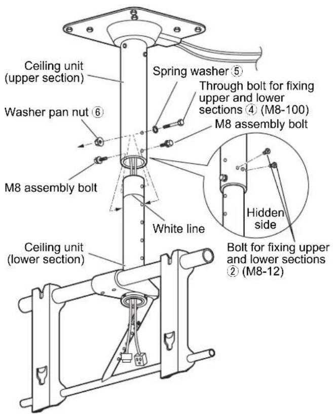
③ Remove the two M8 assembly bolts from the ceiling unit and separate the upper and lower sections of the unit.
- Use the removed M8 assembly bolts when attaching the ceiling unit (lower section).
Note
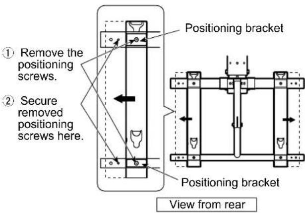
If using a 58-inch plasma display, adjust the attachment brackets as shown in the figure.
① Remove the positioning screws (top and bottom), and slide the positioning brackets and attachment brackets as indicated by the arrows.
② Align the screw holes, and secure with the removed screws.
(Adjust the opposite side in the same way.) (Tightening torque: 1.5 to 2.0N· m )
3. Install the ceiling unit (upper section)
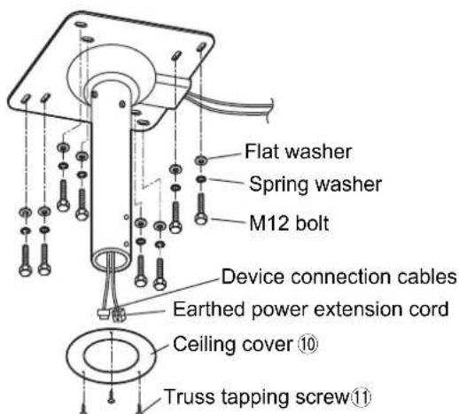
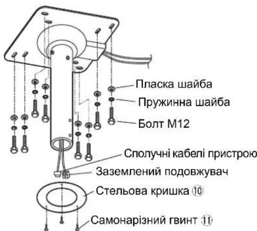
① Before installing the upper section on the ceiling, pass the wiring through the pipe as shown in the figure on the right. Use an earthed extension cord for the power cord (not supplied). Pass the other device connection cables through the same way.
② Make holes for inserting M12 bolts on the ceiling using a method appropriate for the ceiling structure. Install the upper section using a hex socket bolt (M12) (not supplied), flat washer and spring washer.
* Attach a ceiling cover to the ceiling board if needed using three truss tapping screws.
Notes
- Reinforce the ceiling if it is not strong enough.
- Use bolts appropriate for the ceiling material (not supplied).
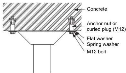
- Refer to the installing examples for wooden structure and concrete structure.
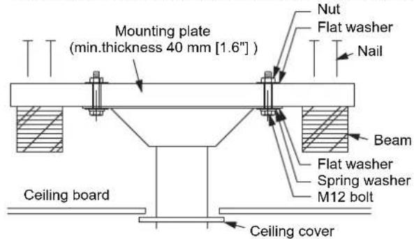
- Installing to a wooden structure (example) - Installing to a concrete structure (example)
4. Attach the ceiling unit (lower section)
① Pass the cords and cables extending from the ceiling unit (upper section) through the pipe of the ceiling unit (lower section).
② Align the height adjustment holes of lower section of the ceiling unit with the holes of the upper section. Pass a spring washer ⑤ over the through bolt for fixing upper and lower sections ④ and pass the bolt through the ceiling unit adjustment holes. Then, temporarily tighten with a washer pan nut ⑥
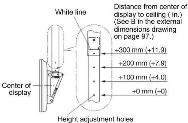
Note
- No more than four height adjustment holes should be visible. (The white line should not be visible.)
③ Temporarily tighten the two M8 assembly bolts removed in unit preparation.
4 Tighten firmly using the two bolts for fixing upper and lower sections 2. Tighten further the bolts tightened temporarily in the steps 2 and 3. (Tightening torque: 8 to 10N· m
5. Preparing the plasma display
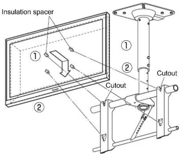
Attaching the insulation spacers
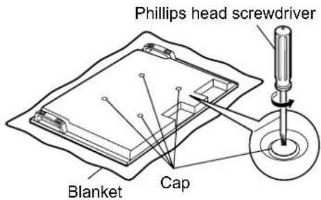
① Place the front surface of the plasma display on a clean cloth that has no dirt or foreign objects on it, and follow the procedure below. If the plasma display has any protruding parts, take care not to scratch or damage them.
② Remove the four caps from the plasma display using a Phillips head screwdriver.
Note
- Keep the caps that were removed in a safe place. (They will be required if you use the pedestal.)
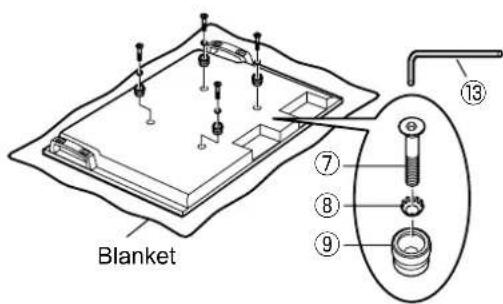
③ Using the supplied Allen wrench 13 , mount the supplied 4 Allen head countersunk screws ⑦ , 4 dished toothed washers ⑧ and 4 insulation spacers ⑨ at the locations where the caps were removed as shown in the figure on the right. (Tightening torque: 3 to 4 N·m)
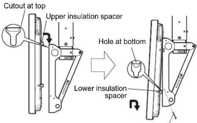
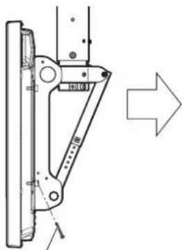
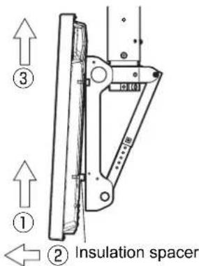
6. Mount the plasma display in the ceiling unit
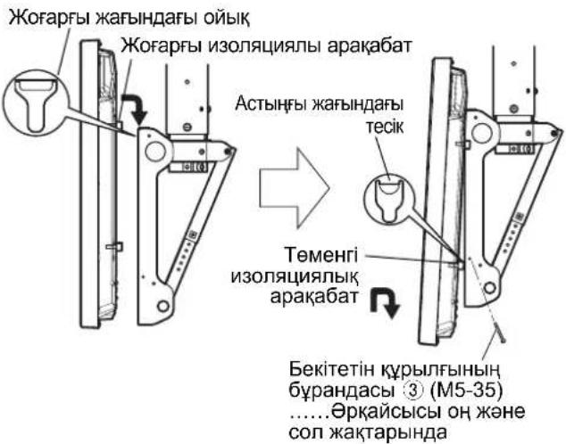
① Engage the upper insulation spacers of the plasma display with the cutouts of the ceiling-hanging bracket, and slowly lower the display into place.
② While lifting the plasma display slightly, insert the lower insulation spacers into the holes at the lower part of the ceiling-hanging bracket.
CAUTION
- If the plasma display is lifted too much, its top part will become disengaged from the ceiling-hanging bracket.
③ Lower the plasma display onto the ceiling unit.
Fix two screws for securing unit to the holes for those screws on the left and right sides of the ceiling unit.
(Tightening torque: 1.5 to 2.0N· m
Notes
- Be sure to tighten the screws for securing unit ③ to their base to prevent the display from coming off.
- Lift the plasma display slightly, and check that it is firmly secured in place.
Screw for securing unit (M5-35)....One each on right and left sides
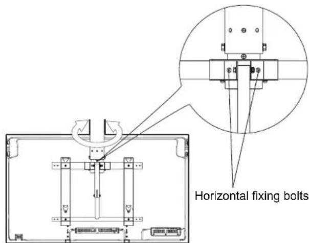
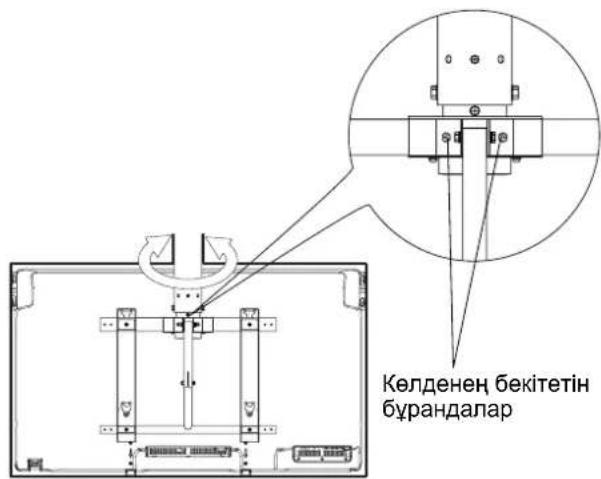
7. Adjust the ceiling-hanging bracket
① Direction adjustment
Loosen the two horizontal fixing bolts. After adjusting the direction of the plasma display, retighten the loosened bolts to fix in place.
(Tightening torque: 6 to 7 N·m)
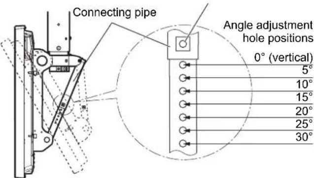
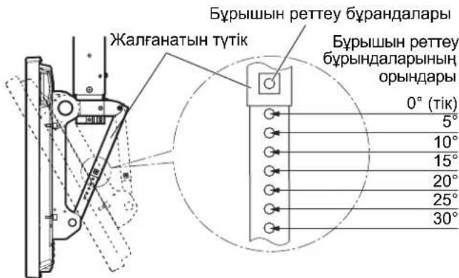
② Angle adjustment
This ceiling unit can be placed in 7 angles from 0^ to 30^ in 5^ increments.
If you wish to adjust the angle, remove the angle adjusting screws from the connecting pipe and select the corresponding position of the angle adjustment holes. Then reinsert the screws.
(Tightening torque: 3 to 4N· m )
Angle adjusting screws
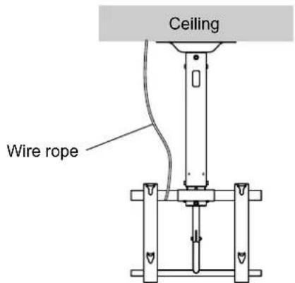
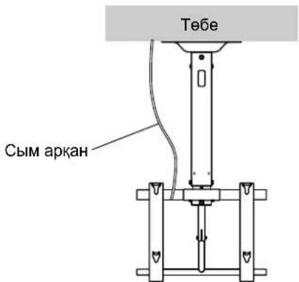
8. Measures to prevent falling
When taking measures to prevent the bracket from falling down, ensure the weight of the ceiling-hanging bracket can be supported.
To ensure that persons in the immediate vicinity will not be struck in the event that the ceiling-hanging bracket slips out of position, use at least one wire rope with some slack to prevent the bracket from falling down.
- For measures to prevent bracket from falling down, use a commercially available wire rope.
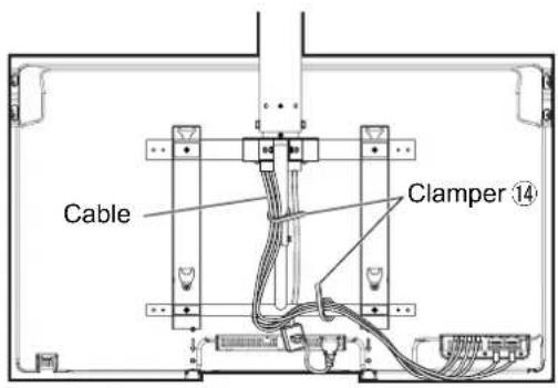
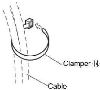
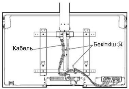
9. Gather the cables
- For details on wiring, see the instruction manual of the plasma display.
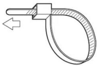
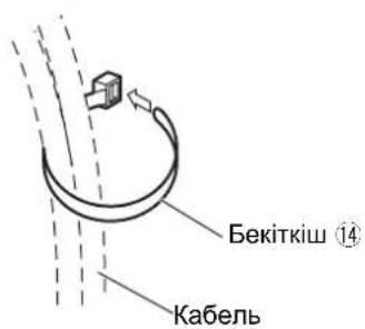
- Bundle the cords and cables connected to the terminals at the bottom of the back side of the plasma display, and secure them using the two clampers 14.
- Do not bunch the power cord together with other cords and cables.
Removing the plasma display
- Return the ceiling unit angle to 0^ , then remove the two screws for securing unit ③ on the left and right sides of the ceiling unit.
① Lift the lower part of the plasma display,
② pull outward
③ and lift upward.
Screw for securing unit (M5-35)
Warning
He pa36npaIte n He nepedeJIbBaIte NOTOnOHyb KPOHHTeH.
- 3TO MOKET Bbl3BaTb NOLOMky Hnn NaJeHne DnCnner, a TaKke npNBecTN K TpaBMam.
BbInonHnTe DeiCTBnI npeDorTbaueHn naeHn notoJOnHoro KpoHtTeHa.
- Henolhoe co6IIOeHne npabun yctahOBKn MOKET npuBecTN K TpaBMam NIN daKe Jetahomy NCXOy.
ПЕДОCTЕРЖЕНИ
He nCnoJIb3yIte PIIa3MeHHbIe DcNnEn, OTIIuHaIOUncEe O T npBVeHbIX B KaTaJIore.
B npotnbom cnlyaee annapat moket ynactb n nobpeintbcra, n 3TO MOKET npNBecTn K TpaBme.
He BbINONHnYe yCTaHOBky B MeCTax, NOBBePKeHHbIX BO3DeIcTBnIO BNaXHOCTN, NbII, NbIMa, npa IIIN HarpeBaHn.
- 3TO MOKET OKa3aTb OTPucaTeNbHoe BnHHe Ha Nla3MeHHbI DUCNJIe IN PnBecTn K BO3ropaHIO IINIPOpaxKeHIO 3JNEKTPnueCKM TOKOM.
He yctahabnBaTe 3kpaHOM, o6paueHHbIM BBepx, B CTOPOHy HIN BHN3.
- 3TO MOKET npBecTN K HAKONJIeHIO TeNla BHyTpN IJa3MeHHoro DnCIIeR, YTO MOKET Bbl3BaTb NOxap.
He NobicaTe Ha IJa3MeHHOM DcIJIe HIN NOTOnIOChOM KPOHTeHHe H He BeaTe Ha HIX KaKHe-JIn6o PpeMTebl.
-ПлайзMeHHbIДиСпЛeМоЖeТУпаТь,ЧТо МОЖeТСАТь пИчИнOH BO3HнHOBEHЯ TpaBM.
He 6Ioknyte BeHTnlaOnHHbIe OTBepCTna. IcnoJIb3yra NOToIOuHbIKPOHwTeH, He 3aKpbIBaIte npoctpaHCTBO BOKpyr nJa3MeHHoro dncnJeA.
B npotNBHOM cnyae TENIO MOKeT HAKONITbC BHTPN N Bbl3BaTb NOkap.
Ipn c6opke n yctaHOBKe KPOHtEynHa dny KpeNHeHa noTOJok y6eHTecb H naExKHOCTn 3aBNHcBAHN BnHTOB BO BCEx MecTaX.
- Pe3yIbTaTOM c6OpKn, npOBeHHeHn HeHaIeKaIuM o6pa3OM, MoKet CTaTB HeIOCTaTOHna IpoUHOCTb; DnCnne yNaTe, n 3To npBEdET K erO NOnOMKe n CTAHe T pNvHNO B03HnKHOBEHn TpaBM.
OCTaBBte XOTy 6bI 10 cm CBO6oHORIO IPOCTpaHCTBa Bblwe, HNXe, Cnpaba N CneBa OT IIa3MeHHORO dncnner. OCTaBBte TAKKe KAK MHNmym7 cm C3aDn DnCnner.
- HecobnHoeHeN 3Tnx peKomeHdaqun MOKeT NOBneYb 3a cO6oB Bo3HnKHOBeHne NoXapa.
Pa60tI no yctaHOBKe i ChrTIO nna3MeHHoro dncnner DoJXhbl BbINOHNrTbcra, no KpaHne Mepe, BDOeM.
KpoHTeHHH Kynan KeTyIe Kon 6epMey wapanapbI KOndaHbInFaHa, Te6ere iNetIH KPOHTeHHHcAnMaTbIH KTepe aJtBHeHaKe3 KeTki3iHi3.
Te6ere ineTIN KPOHHTeIN OPHbIHAn XbIINkbIFAH KaDaIIaXaHbIHDAfbI aamdapdbH XapaKaTTaHybIH 6oJIbIPMay MaKcTaBHda KPOHHTeHHH KJyAbybHa XON 6epMey ywiH KeiHde 6ip cbIMdbI naDanaHbIHbI3.
-KpOnuTeHHH Kynan KeTyIe XoJ 6epMey wapanaPbI ywiH caTbIn anbIHFaH cbIM apKaHaBn naJaHaNbHbI3.
9. Ka6eIbIepdi XnHaI KOHyHbI3
KanfayTypaIbI MaIImETepi INa3MaIbIK DnCIIeIH naIdaIaNHysbI HyckayIbIFbIHah KapaHbI3.
-Ⅰπa3mabik dncnneiH apKbI KaBihH TeMeHri 6eJIirHderi TepMNHaDapra KocblfA H cbIMap MeKa6eBdepdi KINHAN, eki KbickblneH 14 KbICTbpIn KOBIHB3.
KopekUnhypbHb6aca cbImdapmeh KHe Ka6eIbdepmH 6ipre 6aIamaHb3.
He BCTaHOBNIIOte Bnpi6 y Micx, HENpndaTHnx dna BNTpmyBaHHaHaBaHTaXeHb.
- YKUO Mlue dIy MOHTaXy HeoCTaTHbO MIuHe, Bnpi6 MoKe Bnactn.
IpekeohTeC, 0o Micue, de MOHTyBaTMeTbcra Bnpi6, dOCTaTHbO Miue IJRA 3a6e3neHHe TpNBanoro BKNOpNCtAHN KpinJIeHH.
- YKIO 3 yAcOM MiUHicTb CtaHe HeoCTaTHbOIO, NnA3MOBn DnCnNe MoKe Bnactn i 3aBdatn TpaBMn.
He po36upaTe i He moDnphiKyte KPOHwTeH dIa KpInnEnHa CTeHIO.
- Lc MoKe npn3BecTn Do nOwKOxHHeA6o NaIHHe npNCTpoI OTPMaHH BHaCJIIOK cboTO TaBMn.
BukohaiTe i3 3ano6irHna nadiHHIO kpoHtEHa dNkpinneHHa CTeHIO.
- YKUO BUNOHATN BCTaHOBJIeHHA HENOBHICTIO, CE MOKe Ipu3BecTn DO TpaMbYBaHHa 6o HabiBcMeptI.
3ACTEPEXKEHH
BnKOpncToByte Nmwe Ti nna3MObi DnCnJIe, kki HabeDeHi y kaTao3i.
- IhaKHe Bnpi6 MoKe Bnacti i N0wKOdntncr, BoDHOac CnpuHryOHy pN3NK OTPMaHH TpaBM.
He BCTaHOBNIIOte Bnip6 y Micax i3 NiDbNueHO BOJorictH, CKynueHHM NnIy, NMOM, BoJHO npoHO aBO BucOKO ToempepaTPOHO.
Li uHHnMoKyTB HeaTINBHO BnNbaTu Ha po6Otu nla3MOBOro dncnne, a TaKoK cTaTu npuHIO NOxeki YpaxeHH eNEkTpUHm CTpyMOM.
He BCTAHOBIOHTe nla3MOBn dncnne NcboBOO cTOPOHO BROPy, Ha 6oqi a6o HxHbOc TcPOHO DOropn.
- Lc moKe cnpuHnHTN ckyueHH TaBceepHNI pIa3MOBOr Oncnpe, BHaCNIIOK YOrO MoKe BUnHKHyTn NOKexa.
He BnCHiB Ha nla3MObOMy dncnne i a6o kpoHwTeuHi dIra KpInnHHa cTeJIHO Ta He Biawte Ha Hboro JaKi-He6yDb npEaMeTn.
- IhaKSe pna3MOBn DInCnIe MoKe Bnactn 3aBdaTn TpaBMn.
He 6nokynte BeHTnlaui Hi OTbOpn. BnkopncTOByuOn KPOHTeH dIa KpInJIeHHa CTeJIIO, He 3akPnBaTe npocTip HABKONO nna3MOBOrO duCnJe.
- IhaKSe TeNlO MoXe HakoNCHITcRycepeDInHcIcnPruHHHTn NOKeJy.
IiD yac BnKoHaHH po6it 3i 36upaHH Ta MOHTaxy KpOHuTeHHa dJa KpinneHH Ha cTeJIO nepeKoHaTecra, 00 Bci rBnHTn uinbHo 3aTyrHyTo.
- Pe3yIbTaTOM 36npaHH, npOBeHeHOro HeHaIeXHM YInHom, MoKe 6yTu HeIOCTaTHa MiUHicTb; DnCpIeYnaTe, i ce npu3Bede do Ioro noIOMKn n CTaHe pNCHIO BHNKHeHH TpaBMn.
3aHitb xOa 6 10 cm BInbHoro npocTopy Bnue, Hxue, npabOpuy i JibOpuy BiD nna3MoBoro dncnne.
3aHnWitb TAKOX KMIHIMyM 7 cm BInbHorO Micu no3aDy DnCnner.
- HeDToPmAmHnLx peKOMeHdaui MoKe CnpuHHInTn NoXeky.
Yci po60t 3i BCTAHOBnEHn Ta dEmoHTaxy nla3MOBOrO dncnner MaOTb BNKOHYBaTnca OohmHee DbOMa IIOdbMn.
- IhaKwe Pna3MOBn DnCnne MoKe Bnactn i 3aBdaTn TpaBMn.
BukopncObyIe dny yctaHOBN cneuaJIbHI cKlaIObi YaCTHNI.
- HeDToPIMMaHnI cieB BMOrn MoKe IpN3BeCTn Do NaiHHa Nla3MOBOrO DnCJIpe 3i CTeJI Ta/a6o Ioro yUkoJxehn3 3aBdaHHaM TpaBMn IIOHNH.
3akpinitb MOHTaXHI rBnHTi kabeIb XnBJeHHra TAKIM YHOM, IO6 BOH He TOPKaINc BHYptiunx deTaeJcTeJI.
- HeDopummaHnue BmOrn MoKe Ipn3BecTn Do ypaKeHH eNekTpunHm Ctpymom BiKoHTaKTy 36yNb-RAKMn MeTaJIeBMn PpeDMtAMu BCEpeHNI CTeni.
3HimaOuN nna3MOBn dncnne, 3HimaTe TAKoK i KPOHtEyn Dnra KpInJIeHHa CTeJHO.
- IhaKwe Bnpi6 MoKe Bnacti i NowkoDntncr, BodHOac CnpuHryoH np3IK OTpMaHH TpaBM.
PekomeHdaui CTOCOBHO NOBODXeHHA
1) Ybaxho Bn6paTne Micue dny BCTaHOBNeHH Nna3MOBOrO DnCnIe, OckINbKn BHaCNIoK II CBITNa a60 TeNla (y pa3i po3MIeHH No6n3y HarpBaJIbHnx npIaIbAIB a6o NiD npRMM COHcHMM IpOMIHm) BiH MOKe BTPaNTn KOJip Yn DeOpMyBaTncb.
2) YnctbTe DnCnne 3a DonomoroIO M'koI cyxoI raHupK (6abOBHHOI aO oPnaHeJeBOI). RaIO npncpti 3aHaTTO 3a6pydHeHn, Cnoatky 3mHte 6pyd po3HNOM HeHTpaJbHOro MMoYOrO 3ac06y, a NotIM npotpi cyxOIO raHcIPKOIO. He BnKOpNCToBMyTe MNIOI 3ac06n, Taki JK bEN30I, PO3HNHK aO bIC K dN Me6nIB, TOMy IIO IX 3actocyBaHHM MoKe npu3BeCTn Do BiDnyUeHHN Hap6n. (Lio6 Di3HaTnsc, Jk NCTNTn PnA3MOBn DnCnne, DNB. IHcTpKciIO Do DNcNpe. PpN BnKOpNCtAHHi ximiuHO 06po6NeHOI TKaHHN CNoaTky yBaXHo IpouNaTe IHcTpKciI Do He.)
3) He npinkpinnrte ninky ctriky qu Haninkn do Bnpo6y. Lc Moke npn3Bectn do 3a6pydneHH noBepxhi KponuTeHa dna KpinneHH Ha cTeHIO. 3anobiraTe TpnbAnomy KOHTAKTy npntpoio 3 rymOBmN, BiHIOBmTa NODi6HMn Bnpo6amn. (Lc npn3Bepe Do noripweHH BlaactNbOCTeepnctpoio.)
4) NaHEnb nna3MOBOrO dinCnner 3po6neHa 3i ckna. He DoKnaJaTe Do Hei HaNmipHy cnly N he NiIaBaAte II yDapam.
3ACTEPEXKEHHY:
LcHn Hn Hn KPOHn EHH npu3HaueHn Inne dIy nla3MOBx DncnneB Panasonic (DVB. cTOp. 96-97). BkopnCTaHH 3 IHmIMn npctpOM MoKe pN3BeCTn Do HeaaiHOi fikCaJI, IIO MOKe CnpuHHTn PN3NK OTPMaHH TpaBM.
MOHTAXI IOBUNHEH BIKOHYBATNC BIELIAJICTAMN. KOMNAHIA PANASONIC HE HECE BIIOBIAJbHOCTI 3A Bydb-RAI NOLKOJXEHNR BLACHOCTI TA/ABO CEPNO3HI TPABMI, BKIOUAcOHy CMEPTb, IIO E HACNIIDKOM HEBINOBIHORO MOHTAKV ABO HENPABINbHOrO OBCJyTOBYBAHHJ.
Ipebipte hAIBHictb ycix DeTanei Ta 0io ix KInbkiCtB BiNobidae 3a3HaueHi.
| ①Стений постп (1) | ②БOLT Ддя зakрления ворхьои та похьои секши (2) M8 × 12 | ③ГВИNT Ддя зakрления постю (2) M5 × 35 | |
| ④Стений пост ддя зakрления ворхьои та похьои секши (1) M8 × 100 | ⑤Пруженинашайба (1) M8 | ⑥Гайka i3шайбю (1) M8 | |
| ⑦ГВИNT i3 утоныю толовкою i3 Вунтішим јechтграннkom (4) M8 × 32 | ⑧Увігунта зубачашайба (4) | ⑨IзOLЯЧИЕ на рокладka (4) | ⑩Стениь кришka (1) |
| ⑪Самонарізné ГВИNT (3) | ⑫ГВИNT обм_EXEGНЯ обертыня (1) M6 × 8 Пруженинашайба (1) M6 | ⑬Торець Клич (BXODITь до КOMПLEКТY) (1) | ⑭Фіксуний писстп (2) |
[3o6paXeHHaY cybomy nociHnky noaHTbc JIiue 3 iINOCCTpaTNBHOIO MeTOIO.]
3aTepekHi 3axoHn iD yac MOHTaKy KpOHwTeHnA dIy KpInneHHa Ha cTeHIO
Danae ObnaHaHnE KPOHwTeHOM, np3HaueHm Iy KpInneHHa H CTeni INa3MOBOrO DcNpe 3 MeTOIO neperJy. KoHCTpyKuIg KPOHwTeHHa He Do3BOJIe Noro BCTaHOBNeHHa IHUNX NOBepxHx 3 TAKOHO HAiHicTIO, kH a CTEJI.
3a6e3neHTn HaleXHe cyHKIOHyBaHHI pna3MOBOrO DnCnpei 3ano6iITN BUNKHeHHIO HecnpaBHOCTe, He cnId Ioro BCTaHOBNbATu y TaNX Micx.
-Побиу розпскУваib a6o noжжнx/ДмOBnx DeTeKTopiB
B Miczex, ne ep n3nk Bn6yxy uepe3 Bi5paqio a6o noTobx
-Пби3уВиСОКOBОЛьнхДрOTiB a6O dHamiHnx 6NOKiK JKNBHeHHA
- Nopn3y dxepei MarHITHO rno, Tena, npa a6o caxi
B Micx, 0o ndaHbCBAHbNy nobItpy, 0o BnDyBaTbc3 onaIIOBaJbHorO oNaHaHH
B Miczx, De moxyb yTBopIOBaTnckpanJI KOHdeHcAty BiK OHnIioHepiB nobITpr afo iHoro oBnaHaHHa
Iic MoTAtKy BnKOpNCTOByIe MeToD KpInnHeHry, kyn HaiBilbWe BiINoBIaE CTpykTypi Ta MaTepiany NOBepxHi, Ha kii BCTaHOBNIbBATmEtBCr KPOHtEnH.
Iic mohtaxy kpoHteyHa do cTei neBHOCTpykTpyn BIKOPNCOTByte TaKm MeToK pInneHHra Ta enemHTN KOHcTpyku, iKa Hai6JIbSe NiXoJrTa Do MaTepiany KOHKpeTHoi NOBepxHi.
Cπid 3a6e3neHTn HOpMaIbHy BeHTnlaqio, Μo6 Tempepaty a npimieHHe nepeBnuybaJ40°C. HeotpmaHHNcBOrMOxtePn3BeCTn Do HAKONueHHTeJIa BCEpeHNI pna3MOBOrO dncnJe i cnpuHHNTn Ioro HecnpaBHicTb.
Po3ctenIb M'ky KOBpy a6o TKaHnHy Ha niJno3i DJIra TORO, 0o6 niJ yac CKnaDaHHa Ta MOHTaKy Pna3MOBn Incnnr Ta nIOra He noDprnAInc.
PnckpinneHHI detae He 3aTaryTe TBHNTu 3aHaTO CINbHO, aJe He DonyckaTe HeoCTaTHbOro 3aTaryBaHH.
Iid yac Bukohannr po6it 3 MoNTaxy npdiinlty oO6nBy yBary 6e3nei pObooro Micra.
He MoKHa MOHTyBaTu NnA3MOBn DnCnne B6eNocepeHbO NiD OCBiTNeHHa HcTeNi (TaKIM, RaTOKBi CBITNbHnKi, npoxekTopu a6o ranorehHi naMn).
Le MoKe npns3BeCTn Do deOpMaui abo ykoJxehnnaactMacobnx Detanek Kopnyca.
(Moment 3aTaryBaHH:1,5-2,0H·M)
3. YctaHObKa CTeIbOBOrO npnCTpoo (BepxHboi cekii)
① Nepw Hix BCTaHOBnOBaTH BepXHIO CeKIO HA CTeIIO, npocMnKHITb ApOTN Kpi3b Tpy6ky, JIK NOKa3aHO Ha MaIOHky npabOpuy. BnKOpNCToByTe 3a3emJIeHHI NOOBJxvBaW hHpya XNBHeHHa (He BXoJNTb DO KOMJIeK TY NOCTaHaHH).
AhaoriyHM yHOM npocmknHtB iHwi cnoJyHi Ka6eJI npncTPO.
② MetoDM, 00 BiNObiAc cTpykTypi cTeJI, 3po6Ib y cTeJI OTBOpN iD 6OHTM12. BCTaHOBIT BepXHIO cekUIO 3a DOnOMoroIO 6OITa i3 WecTnRpaHHOO roNoBKOIO iD TopueBNI KINu (M12) (He BXoNTb DO KOMNKeTyr NoCTaayHna), Pnackoi wai6n N pyxHHOI wa6n.
* Pπρκπiinitb CTeNbOBy Kpùnkу 10 Do CTeNbOBoI nHnTn, 3a Heo6xɪdHocTi ckopncTaɪTeCra Tpboma camohapi3HmN rBnHTamn ①.

Bvrrn4 33aNy
PpMmTkn
Ma6 ByuBnHO He 6iNbue QotnpbOx OTBOpB INIpeYIOBaHHBAICOTN. (BiNy NiHIO He NOBnHO 6yTu BnHO.)
③ TmUacOBO 3aTnHtB DBA MOHTaxnX 6oTn M8, Bnnyehi nqac nIroTOBn npucptoio.
④ MakcmaIbHO 3aTnHITb DBA 6oNTn IINr 3akpinneHHBepxHboI HxNhBoI cekui ② .PiCnIyBoro 3aTnHITb 6oNTn, nonepeDnbo 3aTnHyTi nID yac BnKoHaHH KpokIB 2 i 3.(Moment 3aTnyBaHH:8-10 H·M)