
TYWK42PV20 - TV PANASONIC - Free user manual and instructions
Find the device manual for free TYWK42PV20 PANASONIC in PDF.
| Product type | Plasma television |
| Brand | Panasonic |
| Model | TYWK42PV20 |
| Screen size | 42 inches (106 cm) |
| Display technology | Plasma |
| Approximate dimensions (W x H x D) | 102.0 x 64.0 x 8.0 cm (without stand) |
| Approximate weight | 22 kg (without stand) |
| Power supply | AC 220-240 V, 50/60 Hz |
| Typical power consumption | 250 W |
| Operating ambient temperature | 0°C to 40°C |
| Main functions | Horizontal and vertical wall mounting, fixing with supplied bracket, portrait/landscape rotation |
| Maintenance and cleaning | Wipe with a soft, dry cloth (cotton or flannel). Do not use benzene, thinner or wax. For stubborn dirt, use a neutral detergent diluted in water then wipe with a dry cloth. |
| Safety | Professional installation required. Do not block ventilation openings. Leave at least 10 cm space around the screen. Do not mount the screen facing upwards, sideways or upside down. Use screws suitable for the wall. |
| Supplied parts for wall mounting | Top/bottom brackets (2), left/right brackets (2), M5x10 screws (8), M8x32 hex head screws (4), toothed washer cups (4), insulating washers (4), long and short tightening screws (2), hex key (1) |
| Wall bracket weight | Approximately 2.3 kg |
| Load capacity of bracket | Designed for a plasma screen; do not install other devices |
| General information | User manual available in 84 pages. Languages: FR, DA, DE, EN, ES, IT, JA, KK, NL, RU, SV, UK, ZH. Technical support via online questions. |
Frequently Asked Questions - TYWK42PV20 PANASONIC
User questions about TYWK42PV20 PANASONIC
0 question about this device. Answer the ones you know or ask your own.
Ask a new question about this device
Download the instructions for your TV in PDF format for free! Find your manual TYWK42PV20 - PANASONIC and take your electronic device back in hand. On this page are published all the documents necessary for the use of your device. TYWK42PV20 by PANASONIC.
USER MANUAL TYWK42PV20 PANASONIC
Fitting work and connection equipment expansion and removal should never be done by any other than a qualified installation specialist.
Incorrect fitting may cause equipment to fall, resulting in injury.
Do not fit at a location that cannot bear the load.
- If the fitting location lacks sufficient strength the equipment may fall.
Include a safety factor when considering the strength of the proposed fitting location.
- If strength is not sufficient the equipment may fall, resulting in injury.
Do not disassemble or modify the wall-hanging bracket.
- Otherwise the unit may be dropped and become damaged, and personal injury may result.
Ensure that the installation location is strong enough to support long-term use.
- If its strength becomes insufficient over the course of long-term use, the plasma display may drop, possibly causing injury.
CAUTION
Do not use any plasma displays other than those given in the catalogue.
- Otherwise the unit may be dropped and become damaged, and personal injury may result.
Do not install the plasma display in any other way than the steps specified in these instructions.
- Otherwise the unit may be dropped and become damaged, and personal injury may result.
Do not fit facing upwards, sideways or upside down.
- This may cause heat to build up inside the plasma display, resulting in a fire.
Do not fit at any locations subject to humidity, dust, smoke, steam or heat.
- This may have an adverse effect on the plasma display and cause fire or electric shock.
Do not block the ventilation holes. When using the wall-hanging bracket, do not block the space between the rear surface of the plasma display and the wall surface.
- Otherwise heat may build up inside and cause a fire.
Secure at least 10 cm (3.9 inches) of space at the top, bottom, left, and right of the plasma display. Also secure some space at the back.
- Failing to do so may result in a fire.
The work of fitting or removing the plasma display must be performed by at least two people.
- The plasma display may fall and cause injury.
For installation, use the special-purpose constituent parts.
- Otherwise, the plasma display may fall off the wall and/or be damaged, possibly causing injury.
Install the mounting screws and power cable in such a way that they will not make contact with the inside parts of the wall.
- Electric shocks may result from contact with any metal objects inside the wall.
When removing the plasma display, remove the wall-hanging brackets as well.
- Otherwise, bumping into the brackets, etc., may result in injury.
Requests regarding handling
1) Exercise care when selecting the location for the plasma display because it may discolor or deform due to light or heat if it is placed where it is exposed to direct sunlight, or near a heater.
2) Clean the wall-hanging bracket by wiping it with a soft, dry cloth (such as cotton or flannel). If the bracket is very dirty, remove the dirt using a neutral detergent diluted in water, and then wipe it clean with a dry cloth.
Do not use benzene, thinner, or furniture wax as this may cause the coating to peel.
(For information on cleaning the plasma display, see the plasma display's instruction manual. If using a chemically-treated cloth, follow the instructions supplied with the cloth.)
3) Do not affix adhesive tape or stickers to the product. Doing so may dirty the surface of the wall-hanging bracket. Do not allow long-term contact with rubber, vinyl products or the like. (Doing so will cause deterioration.)
4) The panel of the plasma display is glass. Do not subject it to a strong force or impact.
Caution:
This bracket is intended for only Panasonic plasma display models (See page 83-84).
Use with other apparatus is capable of resulting in instability causing possible injury.
PROFESSIONAL INSTALLATION IS REQUIRED.
PANASONIC DISCLAIMS ANY PROPERTY DAMAGE AND/OR SERIOUS INJURY, INCLUDING DEATH
RESULTING FROM IMPROPER INSTALLATION OR INCORRECT HANDLING.
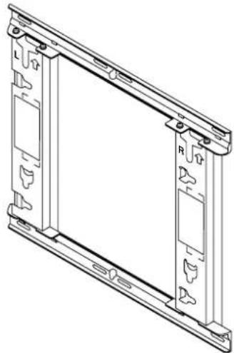
Parts used to assemble the wall-hanging bracket
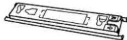
| ① Base upper and lower fitting (2) | ② Bracket base left fitting (1) | ③ Bracket base right fitting (1) | ④ Screw for assembling the fixture (8) M5×10 |
Parts used for installation
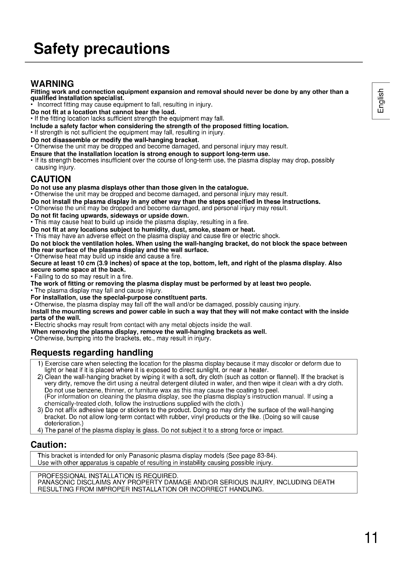
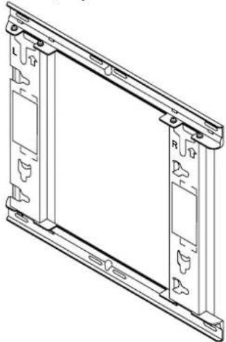
View of fully assembled fixture
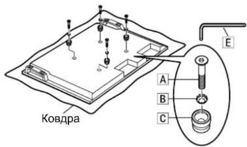
| A Allen head countersunk screw (4) M8×32 | D Screw for securing unit (long) (1) Screw for securing unit (short) (1) |
| B Dished toothed washer (4) | |
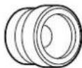
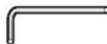
| C Insulation spacer (4) | E Allen wrench (included tool) (1) |
[The images shown in this manual are for illustrative purpose only.]
Precautions for wall-hanging bracket fitting
The wall-hanging bracket is for use in attaching a plasma display unit to a vertical wall for viewing. Do not fit to any surface other than a vertical wall.
To ensure correct plasma display performance and prevent trouble, do not fit at any of the following locations.
Near sprinklers or fire/smoke detectors
- Where there is a risk of exposure to vibration or impact
- Near high-voltage wires or dynamic power supplies
Near sources of magnetism, heat, water vapor or soot
- Locations exposed to air blown from heating equipment
- Where droplets of condensation from an air conditioner or other unit may form
Fit using techniques suited to the structure and materials of the fitting location.
Use commercially available screws with a nominal diameter of 6 mm (0.2 inches) that are suited to the wall material (wood, steel frame, concrete etc.) you are fitting the bracket to.
Ensure good air flow so that the ambient temperature does not exceed 40^ (104^)
Failure to do this may cause heat to build up inside the plasma display, resulting in malfunction.
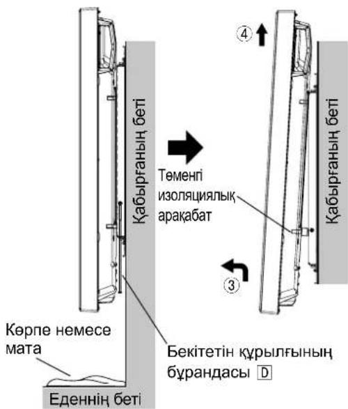
Spread a soft blanket or cloth over the floor so that the plasma display and floor will not be marked or scratched during the assembly and installation work.
When screwing down the parts, ensure that the screws are neither insufficiently tightened nor over tightened.
For the plasma display power supply plug, use a power supply outlet that can be reached easily.
Take sufficient care and ensure safety around you when performing the installation work.
Do not install the plasma display underneath ceiling lamps (spotlights, halogen lamps, etc.). Otherwise, the cabinet may be bent or damaged by high heat.
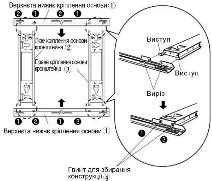
1. Assembling the wall-hanging bracket
① Place the base upper and lower fittings ① and base left 2 and right 3 fittings as shown in the diagram.
2 Insert the projecting parts (tabs) of the base left and right fittings into the cutouts of the base upper and lower fittings (two positions on right, and two on left), and secure the fittings with the screws for assembling the fixtures (4) (two for each) in the order of 1 and then 2. (Tightening torque: 1.2 to 1.5 N·m)
Note
- Please hold the bracket base left and right fittings as you work with the assembled wall hanging bracket. Holding the base upper and lower fittings might deform this unit.
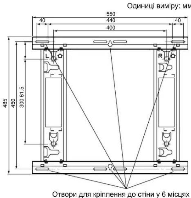
2. Checking the strength of the installation location
① The wall-hanging bracket weighs approximately 2.3kg (5.1 lbs). Refer to the instruction manual of the plasma display, and check the weight of the plasma display unit which will be fitted into the wall-hanging bracket.
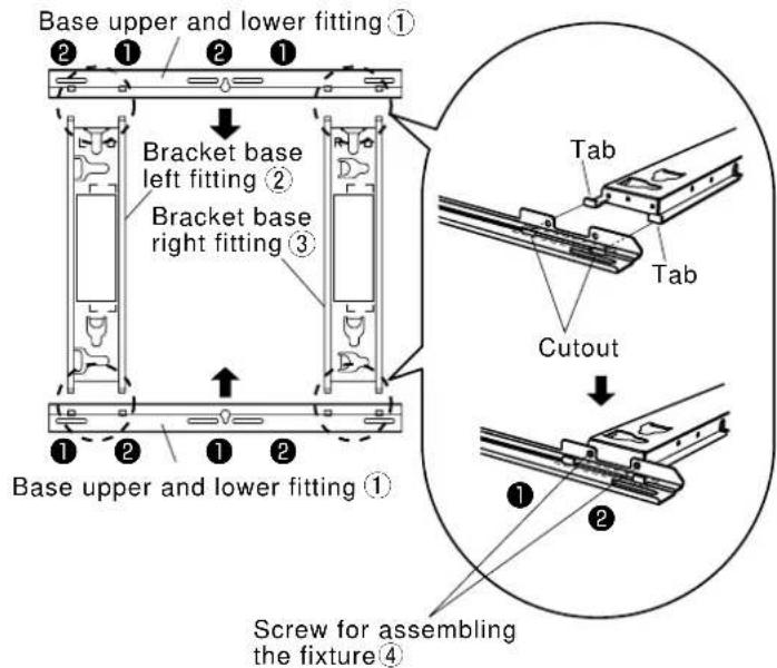
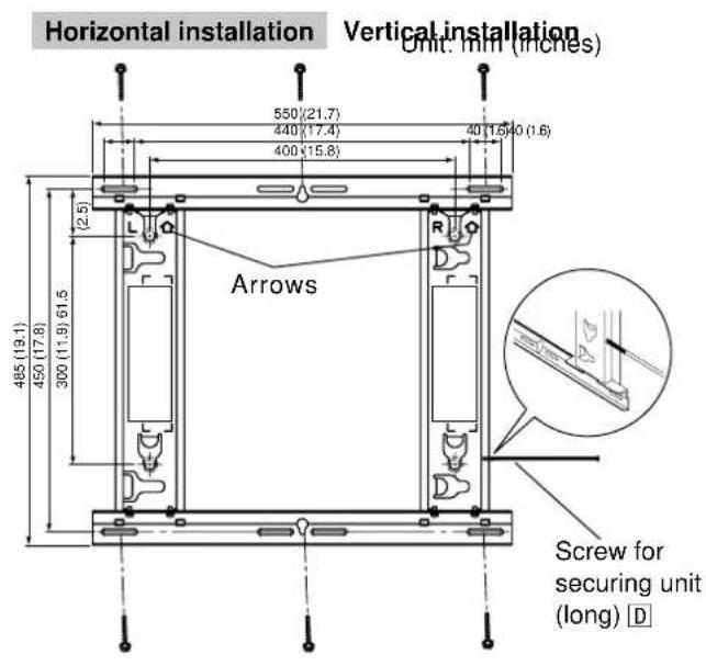
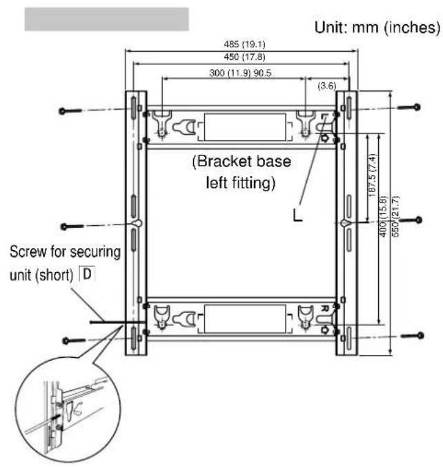
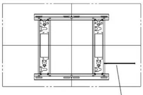
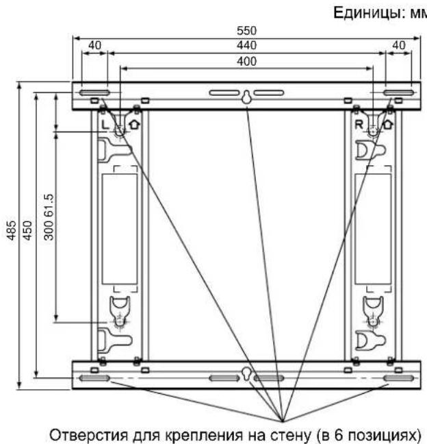
Refer to the outline drawing of the wall-hanging bracket shown on the right, and check the wall strength at the six installation positions shown. If the strength at any of these positions is lacking, provide sufficient reinforcement.
Notes
- There are five pre-drilled mounting holes at the top and another five at the bottom of the wall-hanging bracket. Use the spare holes provided if wood or some other material is used for the wall and a sufficient level of mounting strength cannot be ensured by anchoring the fixture at the six positions shown on the right. However, bear in mind that, depending on which materials the mounting surface is made of, cracks may form on the surface if the screws are used at positions which are too close together.
- Do not mount or place any other product other than the plasma display on the fixture.
- For details on the dimensions applying when the plasma display is mounted, refer to the outline drawing (See page 83-84).
Use the screws without fail to anchor the fixture.
3. Installing the wall-hanging bracket on the wall
① Determine the positions of the wall mounting holes based on the external dimensions drawings (see pages 83 and 84), and attach the bracket to the wall.
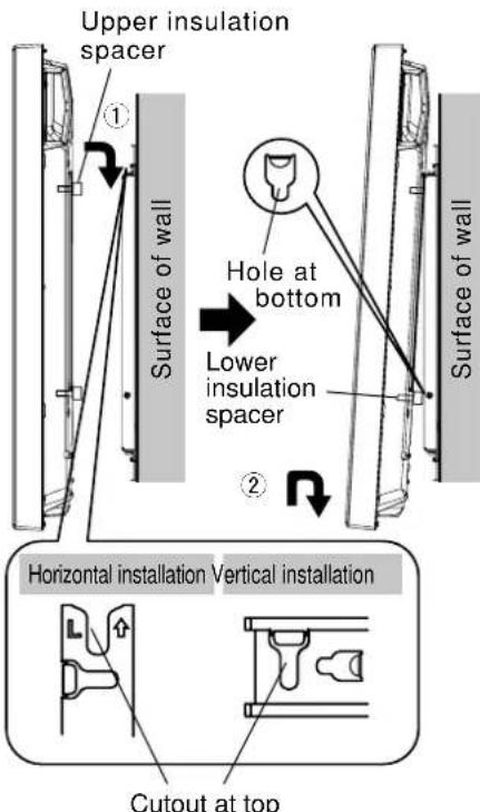
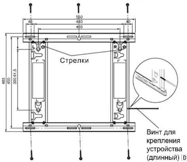
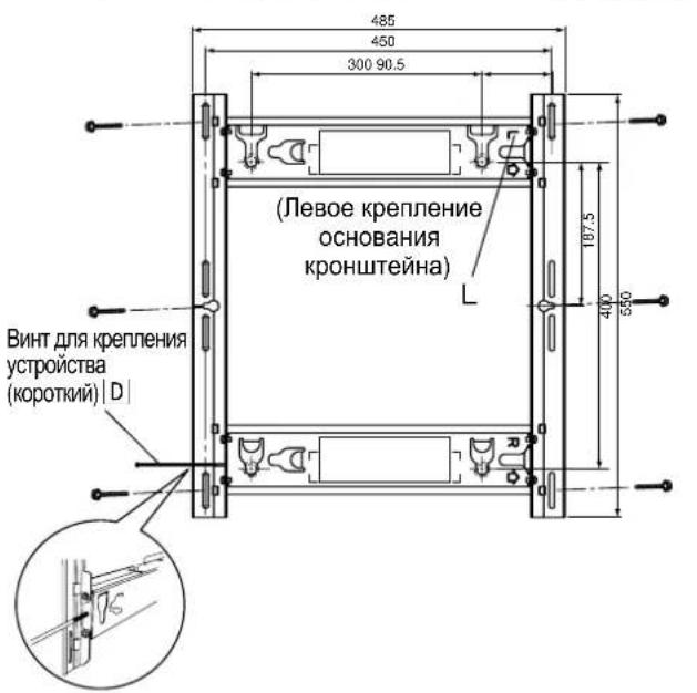
Horizontal installation Attach the wall-hanging bracket with the arrows facing up. Vertical installation Attach the wall-hanging bracket with the direction indicated by "L" at the top. When the plasma display is installed vertically, be careful because the center position of the plasma display will differ from the center position of the bracket due to the structure of the wall-hanging bracket.
③ Use screws or nuts with a nominal diameter of 6 mm (0.2 inches) to firmly secure the bracket at all of the six mounting hole positions.
Notes
- For the wall mounting screws, use commercially available screws with a nominal diameter of 6 mm (0.2 inches) that are suited to the material/structure to which you are fitting the bracket.
- Check the strength of the mounting screws. Use screws that are sufficiently strong.
- If you are embedding the screws, make sure they protrude from the wall surface by 10 to 15 mm (0.4 to 0.6 inches).
- Anchor the screws in at least six locations.
4. Loosely tightening the screw for securing the unit
Insert the screw for securing the to the base left or right fitting and loosely tighten it (turn it two or three times).
Horizontal installation : Screw holes at bottom of side of base left and right fittings
Vertical installation : Screw holes at top and bottom of left side of fitting
(Select and use the hole that will make it easier for you to install the plasma display.)
5. Preparing the plasma display
Attaching the insulation spacers
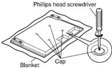
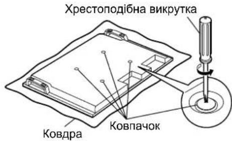
① Place the front surface of the plasma display on a clean cloth that has no dirt or foreign objects on it, and follow the procedure below. If the plasma display has any protruding parts, take care not to scratch or damage them.
② Remove the four caps from the plasma display using a Phillips head screwdriver.
Note
- Keep the caps that were removed in a safe place. (They will be required if you use the pedestal.)
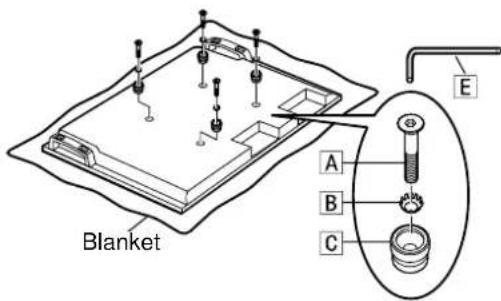
3 Using the supplied Allen wrench, mount the supplied 4 Allen head countersunk screws A, 4 dished toothed washers B and 4 insulation spacers C at the locations where the caps were removed as shown in the figure on the right. (Tightening torque: 3 to 4 N·m)
④ Connect the power cord and the cables for connecting other units.
Notes
- For details on wiring, see the instruction manual of the plasma display.
- When attaching the plasma display to the wall-hanging bracket, take care that the power cord and the cables for connecting other units are not caught between the plasma display and the wall or bracket.
6. Attaching and securing the plasma display to the wall-hanging bracket
- When installing, make sure that the power cord and the cables for connecting other units are not caught between the plasma display and the wall or bracket.
Horizontal installation
① Engage the upper insulation spacers of the plasma display with the cutouts at the top of the bracket unit, and slowly lower them into place.
② While lifting the plasma display slightly, insert the bottom insulation spacers into the holes at the lower end of the wall-hanging bracket, and then pull the plasma display straight down into place.
Vertical installation
Rotate it clockwise 90 degrees so that the Panasonic logo is on the left side, and then attach it using the same procedure as for horizontal installation.
CAUTION
- If the plasma display is lifted too much, its top part will become disengaged from the wall-hanging bracket.
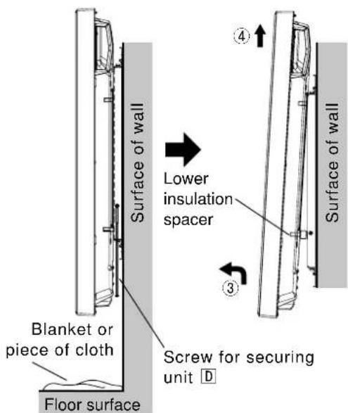
③ Tighten up the screw for securing unit , which was secured loosely in section 4, until it will go no further.
Note
- Tightening up the screw for securing unit | D| too much may cause the bracket to be bent out of shape.
④ Lift the plasma display slightly, and check that it is firmly secured in place.
Horizontal installation
Screw for securing unit (long) D (Tightening torque: 2.5 to 3.5N· m )
Vertical installation
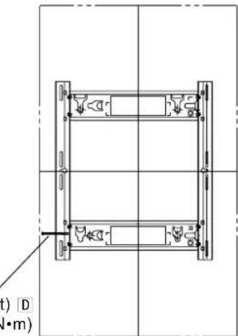
Screw for securing unit (short) D Tightening torque: 1.2 to 1.5N· m
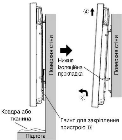
Removing the plasma display
① Place a soft blanket or piece of cloth underneath the plasma display. Remove the screw for securing unit D which is attached to the side of the wall-hanging bracket.
Horizontal installation Left or right side of wall-hanging bracket Vertical installation Left side of wall-hanging bracket
Note
- Otherwise, the screw for securing unit D may drop down by mistake, leaving marks on the surface of the floor.
② Disconnect the power cord and the wires connecting the plasma display to the other units.
③ While lifting the bottom part of the plasma display, pull the plasma display toward you.
After the bottom insulation spacers have been removed, continue lifting up the plasma display and remove it.
Note
- The plasma display needs to be lifted up approximately 4cm (1.6 inches) to be removed.
Warning
Installation vertical
Installation vertical
063aTeIbHO nCnObl3yIe BnHTbI dIra 3akpenJeHnKpnexHoro npncnoc6JeHn.
3. YctaHObKa Ha cTeHy KpoHsTeiHa dIy KpeIeHnHa cTeHy
① OnpeJeIte paCNOJOKeHne OTBepCTn IJI KpeJIeHna HA CTeHy Ha OCHOBE CXEMbl C BHeUHMn pa3MepaMn (CM. cTpaHnCuI 83 n 84) n pNkpennte KpOHsteHn Ha CTeHy.
② Topn3oHTaJIbHa yCTaHOBka PnKpENITE KPOHtEIN DnI KpeNHeHn Ha CTeHy Tak, YTO6bl CTpeJKN yKa3bIBaII BBepx. BepTKaJIbHa yCTaHOBka PnKpENITE KPOHtEIN DnI KpeNHeHn Ha CTeHy Tak, YTO6bl HappaJIeHne, yKa3aHHoe c NOMOsbio “L”, 6bl NO BBepx.y
Korda nna3MeHHbI dncnne yctAHOBnE BepTKKaNbHO, 6ydbTe BHNMaTeNbHbI, NOTOMy TTO CEHTpaNBHO NOJIOXHe Nna3MeHHoro dncnner 6ydet OTNnuatbcr O TcHtpaNbHOrO NOJIOXeHH KPOHtHa H3-3a KOHCTpykCmN KPOHtReHa dner KpennHe Ha CTeHy.
③ NcnoIb3yIte BnHTbI HnI rAkn HOMHaJIbHbIM dAmETpOM 6 MM IIN pOvHOrO KpENHeN KPOHTeHa BO BCEX WeCTn OTBepCTnx DnK PkENHeN.
PpmeaHn
B KaheCTBe BnHTOB DnIe KpeJIeHnHa CTeHy NCIOb3yTe IMeOuNecCB NPOdaKe BnHTbI HOMHaJIbHbIM DNaMeTpOM 6 MM, NOxOJaune dI MaTePnAna/KOHCTpyKUIN, K KOToPbIM Bbl COpaNNc KpeNTb KpOHJTeH.
-Поверпгпpoчнocь крөнхьIx BИNTOB.ИспьзутдоctаTOHNO рpoчнь BИNTbl.
- Ppi BMypOBbIbAHIN BnHTOB pOBepbTe, YTO6bl OHN BbICtynlON OT NObepxHOCTn CTehHa 10-15 MM.
-Пикpenite BnHTbI KaK MHHMmB WecTe MeCTax.
Topn3oHTaJIbHaYyCTaHOBka EHNHULi:MM
BepTKKaJIbHa yCTaHOBka
4. Cbo6oHaJ ФИКcaUЯ BnHTa dIЯ 3akpeIeHnIy 6Ioka
BCTaBBte BnHT nKpEnJIeHn yCtpoIcTbA D B JneBOe nnn npaBoe KpeJIeHne OCHOBAHn n 3aФнкpynte erO Cbo6oJHO (NoBepHnte erO dBa nnn Tpr pa3a).
TOpn3oHTaBHa yctaHObKa :OTBepCTnIy BnHToB BnH3y 60KOBou qactn neBOrO npaboro KpeJIeHIO OCHOBAHnBepTKaBHa yctaHObKa :OTBepCTnIy BnHTa BBePxy N BnH3y neBOu qactN KpeJIeHIO OCHOBAHn(BbIepeTe OTBepCTne, KOtOpoe o6JeerHT yctaHObKy nla3MeHHOrO dncnnner.)
③ KpoHwTeH Heri3iHiH OH JAK 6ekitkiwi (1)
4 Kepek-kaapktbl kypactbipyra aphanran 6ypanda (8) M5x10

Ophaty ywiH naJaHaHbIaTbIH 6eKTeP
TOnbIK KypactbipbnraH 6ekitkiw KypblfbiHbHKepiHici
A ANTbI KbIpNbI OyBik 6aCTbI 6ypaHa (4) M8x32
Ticti dHeec wai6a (4)

D BekTeiH KypBnIbHbIb6ypaHdacbi(y3bIH) (1)
6ekTeiH KypbInfBihInh 6ypaHdacbl (kbicka) (1)
C Okwayarbiu Tecem (4)
E ANTbIKbIpNbKiTT (XeTKi3y XnHaBbHa Kipei) (1)
[OcbI HycayIbIKaTbI cypETep TEK MbIcAJI peTIHe KepcTeITReH.]
Ka6bipfara 6ekiteiH kpoHtienHdi KypacTbipy Ke3iHderi caKtbk wapapanapbl
KoIeHeHHeOpHaTy Ka6bIpraFa IeTIn KPOHtEHHHcN HeMeCe OH XaBf TiriHeH opHaTy Ka6bIpraFa IeTIn KPOHtEHHHcN CoXaBf
Eckenptne
- Θntnece, KpybInfbHbD yctan TypaTbH 6ypaHda 6aKaYcb3da Tycin KETIN, eDeHHIH 6etIH cb3bIN KETyi MymKIN.
② 3neKtp WhpybMeHnna3MaIbIK DnCnIeNi6acka KypblfbnapFa KaIraTbIH cbIMdApDbI axkbpTaHbI3.
③Пиа3MaIbIK dncnneiH actbIFbI XaFBH KeTepeHne, nna3MaIbIK dncnneiDi 03Hi3re Kapai TapTbIHbI3.
④ Temehri apanbik ka6aTap anbHbIn 6onfah coH, nna3MaNbIK dncnnei TaBk KTeepin, OHwewin anbHbI3.
EckepTne
-Пладмалдиспел徳ишewin any yuhih wamamem 4 cm ketepy kepeK.
NONEPEDXEHH
Yci po60Tu 3 MOHTaxy, iDKNIOeHHra 3'EDHyBaJIbHoro 6NaIHaHHra Ta BnIaIeHHra NOBHeH BIKOHyBaTH KBAIqikOBAHn CneuaianCT.
- HenaJIeXHo BnKoHaHm MoTakx MoKe cnpuHHnTu naIHnB BnO6y i npu3BeCTn Do TpaBMvBaHHa.
He BCTaHOBIIoIe Bnpi6 y Micqx, HenpndaTHnx dJI BAHTpMByBaHHaHaBaHTaxeHb.
-Якшо місце дпг монтackу HeioctaTHbO miiHe, Bnpi6 Moxe BnaCTn.
IiD yac po3paxykmyiunocti Bn6paHoroMiCzI dIy MoNTaKy BpaxOByte KoepiciieH 6e3neKn. - Jkso MiuHCTb MOHTaKy 6ynde HeoocTaTHbOIO, BpiO MoKe Bnactn i 3aBdTu TpaBMN.
He po3bnpaIe i He moDnphiKyIte HactiHHN KPOHHTeH.
- Lé Moze npu3BecTn do nouKoJxehH a6o naIHn npucToPO i OTpMaHn BHaCniDOK cIbOrO TpaBMn.
IpekeohaiTeca, 0oMiue, de MOHTyBaTmEtbcra Bnpi6, DOCTaTHbO Miue JIa 3a6e3neuHr TpNBanoro BnKOpNCtAHN KpinJIeHHJ. - YKUO 3 yacOM MlHiCTb CTAHe HeIOCTaTHbOIO, PJIa3MOBn DnCpIe MoKe Bnactn i 3aBdTu TpaBMN.
3ACTEPEXEHH
BukopncToByte IInue Ti nna3MoBi dncnnei, kki HabeDeHi y kaTano3i.
- IhaKHe Bupi6 MoKe Bnactn i N0wKOJNTncra, BOHOnac CnpNUnHryOu np3NK OTPMaHH TpaBM.
IyctaHOBNn INa3MOBOrO dncnner BnKOpNCToByTe IInue Ti di, rki HabeHb B uX IHcTpkyix: He BCTaHOBNIOte npncpi y kOdHn iHwN cnoci6.
- IHaKHe Bnpi6 MoKe Bnacti i NOnKoDntncr, BoDHOac CnpuHryHou nP3NK OTPMaHHra TpaBM.
He BCTaHOBnIOte nla3MOBn DnCnNeJ NlueBOOIO CTOPOHOIO BROPy, Ha 6oCi a6o HxHbOIO CTOPOHOIO DorOpn.
- Lc moKe cnpuHHTn CkyuHHeHr TeNla BCEpeDHI pna3MOBOrO DncJIeR, BHaCJIIOK YORo MOKe BUNHKHyTn NOJExKa.
He BCTAHOBNIOTe Bnpi6 y Micx i3 NiDbNueHO BOIoricTHo, CKyIueHHaM NIIy, DmOM, BoaHOIO npoHO a60 BucOKOTo TEMnpaTPOHO.
- Li chHHNK MoKyTB HeaTINBHO BnNBATn Ha pO6Oy IJa3MOBOrO DnCnIe, a TAKOX CTaTI npuHIO NOKExi YpaxKeHH eNEkTpnuHm Ctpymom.
He 6Nokyte BeHTnlaui Hi OTbOpn. BnkOpncTOByOuH HAcTIHHN KPOHwTeH, He 3aKpNbAte npocTip mix 3aHbOIO NOBepxHeo Pna3MOBOrO DnCnner NOBepxHeo CTiHn.
- IhaKHe TeTnIO MoKe HAKONuHTnCg YcepeHIni CnpuHHTn NoKExy.
3aHwItb xOa 6 10 cm BInbHoro npocTopy Bnue, HxXe, npaBOpuy i JibOpuy BiD nla3MOBOro dncnJe.
3aHwItb TAKoK He6arato Micua 3a dinCnneM.
- HeDoTpmaHnHa cxpeKoMeHdaui MoKe cnpuHHnTn noKeKy.
Yci po60n 3i BCTaHOBHeHH Ta DEMOHTaxy INa3MOBOrO DmCnJIe MaOTb BVKOHYBaTnC rOHaHMeHwe DbOMa NIOdbMn.
- IhaKSe PJIa3MOBn DIncPJIe MoKe BNaCTn 3aBdaTn TpaBMn.
BukopncTOByTe dny yctaHOBN cneuiabHi cKlaIObi YacTHHn.
- HeDToPMaHnH IeI BmOrn MoKe np3BecTn Do naIHn Pna3MOBOr O nCpIe 3i CTHN Ta/a6o Ioro ykoJKeHHa, 3aBdaOu TpaBMn NIOHHi.
3aKpinitb MoHTaxhi rBHTn i Ka6eIb XINBHeHH TaKIM YHOM, IO6 BOH He TopKaHcBHYTpiHix DeTaei CTIH.
- HeDToPMaHnH IieB BMOrn MoKe npN3BeCTn Do ypaKeHH eNEKtpuHm CtpyMOM BiJ KOHTaKTy 3 6yNb-RAKMMeTaJIeBMn NpeDMeTAM BcepeDiHi CTiH.
3HimaOuH nIpa3MOBn dncnne, 3HimaTe TAKoX i HactiHHN KPOHHTeH.
- IhaKHe MoXHa BdApITnCs O KPOHHTeHn ToTo O TpUmMaTn TpaBMy.
PekomeHdauciCTOCOBHO NOBODXeHHA
1) YBaXHo BVbupaIte Mice dIy BCTAHOBHeHH Npa3MOBOrO DnCpIeR, OckInbKn BHaCniDOK II CBITNa a6o TePJa (y pa3i po3MiueHH no6n3y HarpiaJIbHnx npuaIb I abo NiI npraMIM COHcHMM IpomIHm) BiH MOKe BTPaNTn KOJip cN deOpMyBaTNCb.
2) YnCTbTe HactHHN KPOHSeH M'KIO cyXO TKaHNHO (HaPnKna, 6aOBHNO a6o fNaHeNo).
KIO KOHO TcJIbHO 3a6pydHeO, 3MnIe 6pyd BOHnM PO3uHOM HeITpaJIbHO rMOUOrO 3ACOBy, a
notIM BnTPIb KPOHSeH cyXO TKaHNHO. He BnKOpNCTOByte 6eH30J, PO3uHnK a6o BICK dJa Me6nIB,
Tomy IIO IX 3AcTOcYBaHH MoKe npns3BecTu Do BiDnyueHHaFap6n NOKpTTT.
(IIo6 Di3HaTncA, kY nCTHTn PnA3MOBn DnCnNe, INB. IHcTpkyiio Do DnCnJe. Ppn BnKOpNCtAHHi ximHyO
6bp6JeHO tKaAHHH CnoaTky yBaXHo npouHTaTe IHcTpkyiio do Hei.)
3) He npinkpinnrte IINKy cTpiky uH aninkn Do Bnpo6y. Lc MoKe npn3BecTu Do 3a6pydneHH noBepxHi HacTIHHoro kpoHsTeHa. 3anobiraute TpuBaIOMy KOnTaKTy npncTPO 3 rymOBmN, BiHIOBmN Ta nOdi6HMn Bnpo6amN. (Lc npns3BeDe do noripseHH BnactNBocTee npncTPO.)
4) NaHEnb nIa3MOBOrO dinCnner 3po6neHa 3i ckna. He DokNaDAaTe Do Hei HaNIMHy cnly N he NiJaDaBaTe II ydapam.
3ACTEPEXKEHH:
Ley HactiHnn KpoHtEn H np3NaHeH nnIe DnIa3MOBux DncnIeB Panasonic (INB. cTOp. 83-84). BnkopntAHn 3 IHsIMN pnpCTpOAM MoKe np3BeCTn Do HeaDiHoi fikCaJI, 0o MoKe CnpuHHTn PnIK OTpMaHn TpaBM.
MOHTAXIIOBUNHEH BIKOHYBATNC BIEJIAJICTAMN. KOMNAHIR PANASONIC HE HECE BIDIOBIAJIbHOCTI 3A BUYB-RAI NOIKOJXEHNBAJACHOCTI TA/ABO CEPNO3HI TPABMI, BKJIOUACOUc CMEPTb, IIO E HACNIKOM HEBIDIOIBHOHO MOHTAKV ABO HENPABINbHOFO OBCLYTOBOVBAHHJ.
②ЛIBE KpInJIeHnO OCHOBNKPOHHTeHa(1)
PnckpnnneHHi deTaeH He 3aTaryTe rBHTn 3aHaTcNbHO, aJe H e DonyckaTe HeoCTaTHbOro 3aTaryBaHH.
UTeNcEJIb shHpya KINBJIeHHnIpa3MOBOrO nIa3MOBOrO nIOBHeH IeRKO dIcTaBAtn Do eJekTpuHoi pO3ETKn.
Iid yac BIKOHaHH po6it 3 MOHTaxy npdiinb oc6nby ybary 6e3nei po6oHOrMicra.
He MoKHa MOHTyBaTu NnA3MOBn DnCnIe 6e3NocepeHbO nID OCBITNeHHa HcTeIi (TaKIM, Jk ToHKoBi CBITNbHKn, npOKeKTOp a60 ranoreHHi lamnn).
LcMoKe npn3BecTn do deΦopMaui a6o yuKoJxHn PnactMacOBrN DeTaJe KOpnyca.
1. 36иранн hactiHHoro kpoHштейнa
① BcTaHOBITb BepXHc HnXHc KpInNeHHOCHOBN ① TaJIbe ② npaBe ③ KpInNeHHOCHOBN,AK NOKa3aHO Ha CXemI.
② BcTaBte BnCTynaiouy qactHn (fikcatopn) IIBORO n npABORO KpInneHb OCHOBN y Bnpi3n BepxHBoro HnXhBoro KpInneHb OCHOBN (Dba Micu npABOPuy i Dba IIBOPYU) 3akpinitb KpInneHHraBHTAMn DnA 3bnpaHHKoHCTpyKuII ④ (Dba dna KOKHOro) y npAky 1, a notim ③ . (MomeHT 3aTaryBaHH: 1,2-1,5 H·M)
Pnmitka
- YtpmyTe Ibe Ta npabe KpInneHnO cHObN KpoHsTeHa nIac po6oTu i3 3i6paHm HactIHMM KpOHsTeHOM. YtpmaHHa BepxHbOrTo Ta HnKhBOrO KpInneHb OCHOB MoKe npIN3BeCTn Do deOpMauiBnOby
2. Перавпа мiochocti CTINB MiczaX MOHTaKy
① HacTihHKnKpOHwTeH BaxHTb npn6n3HO 2,3Kr. NItbcIhCTpyKzIO DO nna3MOBOrO Dncnner, zo6 nepeBipTN Bary nna3MOBOro dncnner, kNk 6yde 3akpinneHo Ha HAcTHHOMy KpOHwTeHi.
② NbiBcCxemTuHKepecnHHaactiHHoro KPOHTeHa npabOpuy,06nepeBipTu MiHCTb CTIN B WeCTu MicxMOHTaKy KOHCTpyKuII. JkUo 6yDb-Ke 3 uXMicu HeIOCTaTHbO HaIHe, OdoaTKOBO yKpinitb Noro.
PnmiKu
PnTb nonepHb npocBepnHex OTbopib po3miuhi y BepxHH qactni, a HHI pTb— y HNXH qactnHi hactiHoro kpoHtneHa. BnknpictOByte doatkOBI OTbOp, kIIO CTHy 3pO6JIHO 3 depeBa a6o IHUoro MaTepiany, 0 He Do3BOJRE DOcARTN oTpiBHO rPiHr MiHOCtI KpINHeHm KOHCTpyKuB B wctN MlCux, R noka3aHo Ha KpcEeHH Ipabopyu. Ondak MaTe Ha yBa3i, 00 3aJeXHO bMATEpiany, 3 KORO 3pO6JIHO CTHy, HA NOBepxHH MoKyTB 3'BBNTncr TPIuHH, kIIO rBHTN 6dyTB po3taWobahi DyKe 6bn3bKO OINH DO ODNHO.
- PpNkpInIIOHe Do KOHcTpyKuII Nnue nna3MOBn Dncnne: He HamaraTeCg PpNkpInNTu Do He JKOden IHmN pnpCTpi.
- ⅢO6 OTpIMaHInHOpMaUHIO npo ToHi po3MIPn 3MOHTOBaHO rIJa3MOBOrO dncJIeR, nBiTbcra CXeMaTHuHE KpeCneHHr (INB. CTOp. 83-84).
06OB'3KOBOBVKOPNCOTByTe TBHNTI DJI 3akpInnHeHH KOHCTpykcii.
PpknIeHHI3oJIuHINx npoknaOk
① Po3TaWyIe TnIcBoBy NOBepxHIO nIa3MOBOrO dncIeR Ha YnCTi TkAHHI 6e3 6pydy a6o CTOpOHIX npedMeTIB i DToPmMyTEcB npoeDpyN, ONncaHOI HnXyE. RaIoo Ha nIa3MOBOMy dncNneI c BnCTynAHOi Detani, noD6aHTe npoTe, uo6 He nOdpnATn He yWkoNDtN ix.
23a donomoroo xpectonodioBnKpyTKn 3HIMtB i3 nna3MOBOrO DnCnnner YoTnp KOBNaqKn.
PpIMITka
- TpmaTe MOHTaXHy NiCTaBky i TaKoX 3HRTI KOBnauKIN H aHdHOMy MiCi. (BoH 3HaDo6nTbCry, kUO Bu ByDeTe BnKOpNCtOByBaTu niCTaBky.)
3a donomoroTO TopoeBOrO KIOUoA E (BXOINTb DO KOMNJIeKTy) yCTAHOBiTB 4 BnHTn 3 yTONNeHmM rONOBkAM i3 BHyTpiHIM wecTNrpAHNKOM A, 4 yBirHyTI 3y6acti wa6n B Ta 4 i0JauHHI npOKJaKn C y Micx, De 6yNo 3HrTO KOBnauKN, JIK noka3aHO Ha CXemI npabopyu. (MomeHT 3aTAYBaHH: 3-4 H·M)
④ПикнючынурхиьеHHЯ ta Ka6eni dny niKnueHHa iHux npucptpoiB.
PnIMiTK
- xOdo cxem eneKtpponpoBOKn, nB. IHcTpkyuHIO dny eKcnnyataii pna3MOBOrO duCnner.
PnKpInIIOHn nA3MOBn DnCnne Ha HactIHn KPOHTeH, no6aTe npo Te, 06 shynp kINbEnHH i Ka6eni dnn iNkUoyHH IuNX npCTpoB He 6yIn 3aTNCHTi MIX nA3MOBm DnCnneem i CTHO a6 KOHHTeHOM.
Topn3oHTaBHH MoHTax JIbN a6o npabN 6iK HactiHoro
KpOHTeHa
BepTKaJIbHm MoTax JIbN 6ik HacTIHHoro KPOHHTeHa
Ppimitka
- KIIO UBOHO He 3po6nTu, TBNHT IIN3aKpInnHeHH npNCTPOHO MOKe BUNaIKOBO BNnactu Ta 3aJInuHn NOpPnHn Ha niDnOsi.
② BiD'cHaHTe UHP XNBHeHH Ta Ka6eJI, 3'EDHyOTb Pna3MOBn Dncnne i3 IHUMN npHCTpOAMN.
③ПиДИМАЮЧИ HIXHIO YAcTHy Pna3MOBOrO DnCnIeR,NotaHITb NOro Ha ce6e.
④ NicBn BnDaeHn Hxhix i3OJauHnx npoknaok npoOBkyntiNidHimatn nla3MOBn dncnne i 3Himt b Noro.
PpIMtka
-ⅢO63HHTIINa3MOBn DucnJe, Ioro cniD niHrtn np6n3HO Ha 4cm.
警告
Wall-hanging bracket (Vertical mounting type)
External dimensions drawing
Horizontal installation
Horizontal Installation
Horizontale installment