DCE079D1 - Measuring equipment DEWALT - Free user manual and instructions
Find the device manual for free DCE079D1 DEWALT in PDF.

| Product Type | Rotary Laser Level |
| Brand | DeWalt |
| Model | DCE079D1 |
| Power Supply | 18 V Lithium-Ion Battery |
| Battery Type | 18 V Lithium-Ion (compatible with 1.5 Ah and 2 Ah) |
| Laser Class | 2 |
| Laser Power | < 1 mW |
| Wavelength | 630 - 680 nm (red) |
| Rotation Speed | 150, 300, 600, 1200 rpm |
| Indoor Visible Range | 60 m |
| Range with Detector | 600 m |
| Leveling Accuracy | ± 1.5 mm at 30 m |
| Self-Leveling Range | ± 5° |
| Operating Temperature | -5°C to 50°C |
| Storage Temperature | -20°C to 70°C |
| Weight (without battery) | 4.5 kg |
| Tripod Thread | 5/8"-11 |
| Operating Modes | Self-Leveling, Slope Mode, Scan Mode (0°, 15°, 45°, 90°) |
| Alarm Function | Instrument Height Alert (shutdown and beep if disturbed) |
| Included Accessories | Digital Laser Detector, Remote Control, Wall Mount, Grade Rod, Target Card, Laser Enhancement Glasses (depending on kit) |
| Maintenance | Clean lens with cotton swab and water; clean housing with a non-linting damp cloth |
| Safety | Do not look directly into the beam; Class 2 laser; avoid exposure |
Frequently Asked Questions - DCE079D1 DEWALT
User questions about DCE079D1 DEWALT
0 question about this device. Answer the ones you know or ask your own.
Ask a new question about this device
Download the instructions for your Measuring equipment in PDF format for free! Find your manual DCE079D1 - DEWALT and take your electronic device back in hand. On this page are published all the documents necessary for the use of your device. DCE079D1 by DEWALT.
USER MANUAL DCE079D1 DEWALT
natural_image
Line drawing of a DeWALT brand air purifier with no text or symbols on the body
natural_image
Line drawing of a DeWALT brand air purifier with no text or symbols on the bodyCE

DCE074R
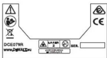
DCE079R
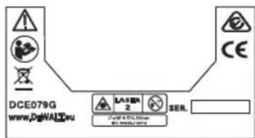
DCE079G
Dansk 6
Deutsch 17
English (original instructions) 27
Español 36
Français 46
Italiano 56
Nederlands 66
Norsk 76
Português 85
Suomi 95
Svenska 104
Türkçe 113
Ελληνικά 122


A
DCE074R
DCE079R/DCE079G
B
©
LOD TILSTAND/SENKLOTMODUS/PLUMB MODE/MODO PLOMADA/MODE APLOMB/MODALITÀ ALLINEAMENTO/LOODMODUS/LODDMODUS/MODO PRUMO/KOHTISUORA TILA/LODLÄGE/ÖLÇÜM MODU/ΛEIT. NHMATOΣ
NIVEAU TILSTAND/NIVELLIERMODUS/LEVEL MODÉ/MODO' NIVEL/MODE NIVEAU/MODALITÀ LIVELLAMENTO/NIVEAUMODUS/NIVÁMODUS/MODO DE NÍVEL/TASOTILA/NIVELLERINGSLÂGE/TERAZÎLEME MODU/ΛEIT. ΑΛΦΑΔΙΟΥ
D
natural_image
Technical line drawing of a mechanical component labeled 'DEWALT' (no additional text or symbols)LOD TILSTAND
SENKLOTMODUS
PLUMB MODE
MODO PLOMADA
MODE APLOMB
MODALITÀ ALLINEAMENTO
LOODMODUS
LODDMODUS
MODO PRUMO
KOHTISUORA TILA
LODLÄGE
ÖLÇÜM MODU
ΛΕΙΤ. ΝΗΜΑΤΟΣ
natural_image
Line drawing of a DeWALT brand air purifier with no visible text or symbolsNIVEAU TILSTAND
NIVELLIERMODUS
MODO NIVEL
LEVEL MODE
MODE NIVEAU
MODALITÀ
LIVELLAMENTO
NIVEAUMODUS
NIVÁMODUS
MODO DE NÍVEL
TASOTILA
NIVELLERINGSLÄGE
TERAZÍLEME MODU
ΛΕΙΤ. ΑΛΦΑΔΙΟΥ
E
natural_image
Technical line drawing of a car interior showing internal components and a labeled component (15), no text or symbols present.F

natural_image
Simple line drawing of a pair of eyeglasses (no text or symbols)
G
H
natural_image
Technical line drawing of a mechanical device with labeled part 21 (no text or symbols beyond label)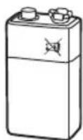
I

J
INDIKATORER/ANZEIGENINDICATORS/INDICADORES/INDICATEURS/INDICATORI/INDICATOREN/INDIKATORER/INDICADORES/INDIKAATTORIT/INDIKATORER/GÖSTERGELER/ENΔΕΙΞΕΙΣ
| Over niveau/Über Bodengleich/Above Grade/For encima del nivel/Au dessus de l'alignement/Sopra I livello/Boven niveau/Über graden/Acima do valor pretendido/Tason y apioolella/Ovan for grad/Seviye Uzerinde/You tnc sußelic | Lidt over niveau/It was über bodengleich/Slightly Above Grade/Ligeramente por encima del nivel/Légèrement au dessus de l'alignement/Leggermente sopra il livello/lets boven niveau/Litt over graden/Ligeiramente acima do valor pretendido/Hiukan tason ylapuo ella/En aning oven für grad/Oraz Seviye Uzerinde/Ekwypó dwa tnc sußelic | Iniveau/Bodengleich/On Grade/En niveau/Aligné/A livello/Op niveau/På graden/Valor adequaco/Öl saalla tasola/På grad/Seviyede/És ačšic | Lidt under niveau/It was unter bodengleich/Slightly below Grade/Ligeramente por debajo del nivel/Légèrement au dessus de l'alignement/Leggermente sotto il livello/lets onder niveau/Litt under graden/Ligeiramente abaixo do valor/Hiukan tason alapuolela/En aning under grad/Oraz Seviye Altinda/Ekwypó situ tnc sußelic | Under niveau/Unter bodengleich/Beow Grade/For debajo del nivel/Au dessous de l'alignement/Sotto II livello/Ünder niveau/Under graden/Abaixo do valor adequado/Teson alapus ella/Unter grad/Seviye Altinda/Kātur tnc sußelic | |
| Insignale/HercareSignaleautibe signalak/Vernalessumoras/supra sonores/segnali acutici/nocoresignaler/esignaler/sinales adibere/kammerlu/junctional/seresi inspaler/cytos/otjuto | hurtigt bip/schneller Alamton/fast beep/pitido rápido/bip rapide/bip rapide/snolle piptoon/rask piping/sinal sonoro rápido /ropea pippeaus/srabba pip/hzhi bip seal / yprýpopo ofjuo | hurtigt bip/schneller Alamton/fazr beep/pitido rápido/bip rapide/bip rapide/bip rápido /snelle pieptoon/rask piping /bip rapide /ropea pippeaus /snabba pip/hzhi bip seal / yprýpopo ofjuo | konstant tone/Daverton/steady tone/tono fijlosan continuiton fibso/constant tone/pen tone/tom fixo/casalinen žäni/cavibruten tan/sabit ton/orbePéç, ngoc | langsont bip/langsemer Alamton/slow beep/pitido leno/spip lent/spip lenta/langze mer piptoon/langsonnt pip/sinal sonoro lent/#das žäni/langsamma pip/yawas bip sesi/cpyö ofjuo | langsont bip/langsemer Alamton/slow beep/pitido lento/bip lent/bip lenta/langzame pieptoon/langsonnt pip/snal sonoro lenta/hitas žäni/langsamma pip/yawas bip seal/cpyö ofjuo |
| display/konter/Display-Symbole/display icons/iconos de visual/zaclón/icone di visual/izza/zone/pictogramm veergeven/displaysymboler/icones de visual/zaçao/naytön kuwakkoet/koner på skarmen/ekran smigeleri/iskow/brd olvijns |  |  |  |  |  |


K
L


M
N
©
P
LASER ENHED ROTERET 180°/LASEREINHEIT – 180° GEDREHT/LASER UNIT ROTATED 180°/UNIDAD LÁSER GIRADA 180°/APPAREIL LASER EN ROTATION 180°/UNITÀ LASER RUOTATA DI 180°/LASERUNIT GEROTEERD 180°/LASERENHET ROTERT 180°/UNIDADE DE LASER EM ROTAÇÃO DE 180°/LASERYKSIKKÖ 180° KÄÄNNETTYNÄ/LASERENHET ROTERAD 180°/180° DÖNDÜRÜLMÜŞ LAZER ÜNİTESİ/MONADA ΛΕİZEP ΣTPAMMENH 180°
Q

DANSK
natural_image
Technical line drawing of a mechanical housing with directional arrows indicating flow or force (no text or symbols)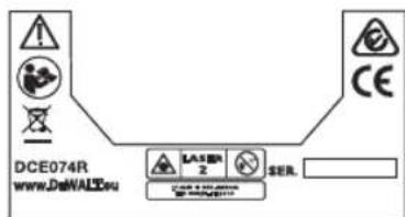
DANSK
Definitions: Safety Alert Symbols and Words
This instruction manual uses the following safety alert symbols and words to alert you to hazardous situations and your risk of personal injury or property damage.
DANGER: Indicates an imminently hazardous situation which, if not avoided, will result in death or serious injury.
WARNING: Indicates a potentially hazardous situation which, if not avoided, could result in death or serious injury.
CAUTION: Indicates a potentially hazardous situation which, if not avoided, may result in minor or moderate injury.
(Uged without word) Indicates a safety related message.
NOTICE: Indicates a practice not related to personal injury which, if not avoided, may result in property damage.
If you have any questions or comments about this or any DeWALTtool, visit our website www.2helpU.com.


Warning: To reduce the risk of injury, user must read instruction manual.
Safety Instructions for Lasers

WARNING! Read and understand all instructions. Failure to follow all instructions listed below may result in electric shock, fire and/or serious personal injury.
SAVE ALL WARNINGS AND INSTRUCTIONS FOR FUTURE REFERENCE
WARNING! Laser Radiation Exposure. Do not disassemble or modify the laser level. There are no user serviceable parts inside. Serious eye injury could result.
WARNING: Hazardous Radiation. Use of controls or adjustments or performance of procedures other than those specified herein may result in hazardous radiation exposure.
- Do not operate the laser in explosive atmospheres, such as in the presence of flammable liquids, gases, or dust. Power tools create sparks which may ignite the dust or fumes.
• Use the laser only with the specifically designated batteries. Use of any other batteries may create a risk of fire. - Store idle laser out of reach of children and other untrained persons. Lasers are dangerous in the hands of untrained users.
- Use only accessories that are recommended by the manufacturer for your model. Accessories that may be suitable for one laser, may create a risk of injury when used on another laser.
- Tool service must be performed only by qualified repair personnel. Service or maintenance performed by unqualified personnel may result in injury. To locate your nearestDEWALT service center go to www.2helpU.com on the Internet.
- Do not use optical tools such as a telescope or transit to view the laser beam. Serious eye injury could result.
- Do not place the laser in a position which may cause anyone to intentionally or unintentionally stare into the laser beam. Serious eye injury could result.
• Turn the laser off when it is not in use. Leaving the laser on increases the risk of staring into the laser beam. - Do not position the laser near a reflective surface which may reflect the laser beam toward anyone's eyes. Serious eye injury could result.
- Do not operate the laser around children or allow children to operate the laser. Serious eye injury may result.
- Do not remove or deface warning labels. Removing labels increases the risk of exposure to radiation.
- Position the laser securely on a level surface. Damage to the laser or serious injury could result if the laser falls.
ENGLISH
WARNING: Use of controls or adjustments or performance of procedures other than those specified herein may result in hazardous radiation exposure.
WARNING! DO NOT DISASSEMBLE THE ROTARY LASER. There are no user serviceable parts inside. De assembling the rotary laser will void all warranties on the product. Do not modify the product in any way. Modifying the tool may result in hazardous laser radiation exposure.
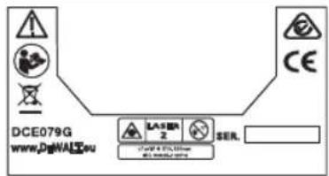
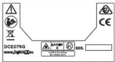
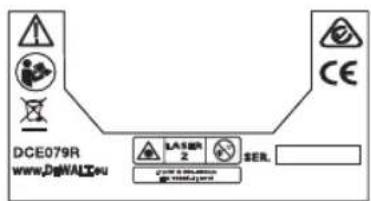
- The label on your tool may include the following symbols.
V....volts
nm......wavelength in nanometers
mW milliwatts
2 ....Class 2 Laser
......laser warning symbol
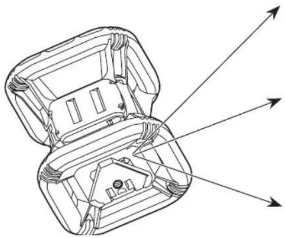
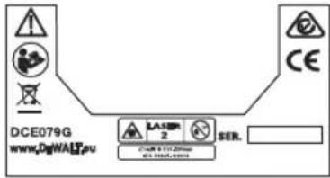
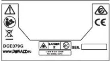
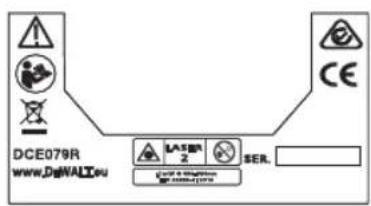
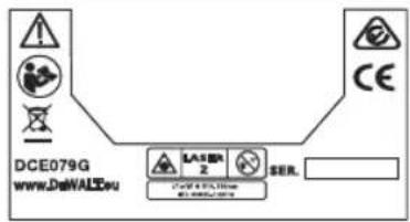
Warning Labels
For your convenience and safety, the following label is on your laser.


WARNING: To reduce the risk of injury, user must read instruction manual.
WARNING: LASER RADIATION. DO NOT STARE INTO BEAM. Class 2 Laser Product

AVOID EXPOSURE -LASER RADIATION IS EMITTED FROM THIS APERTURE
natural_image
Technical line drawing of a mechanical housing with internal components and directional arrows indicating flow or force (no text or symbols)
ENGLISH
EC-Declaration of Conformity
Radio Equipment Directive
CE
DEWALT Rotary Laser
DEWALT hereby declares that the DEWALT Rotary Laser DCE074R/DCE079R/DCE0709G is in compliance with the Directive 2014/53/EU and to all applicable EU directive requirements.
The full text of the EU Declaration of Conformity can be requested at DEWALT Industrial Tool Co., DEWALT Europe, DEWALT D-655-10 Idstein, Germany 65509 or is available at the following internet address: www.2helpU.com.
Search by the Product and Type Number indicated on the nameplate.
READ ALL INSTRUCTIONS
Batteries and Power
This DEWALT rotary laser will accept all DEWALT 18 volt lithium ion batteries, but is built to best resist damage during a fall when used with the following batteries: All 1.5Ah and 2Ah DEWALT 18 volt lithium ion batteries.
Charging the Battery
The battery pack is not fully charged out of the carton. You need to use a DeWALT 18 volt charger to charge the battery pack before you can use the rotary laser.
- Refer to the chart at the end of this manual for compatibility of chargers and battery packs.
- Be sure to read all safety instructions before using your charger.
WARNING: • DO NOT
- DO NOT attempt to charge the battery pack with any chargers other than the ones listed in this manual. The charger and battery pack are specifically designed to work together.
-
Carefully follow all instructions and warnings on the battery label and package and accompanying Battery Safety Manual.
-
Slide the battery pack into the charger as described in the Battery Safety Manual.
- Wait until the battery pack is fully charged.
- Slide the battery pack out of the track.
NOTE: When ordering replacement battery packs, be sure to include the catalog number and voltage.
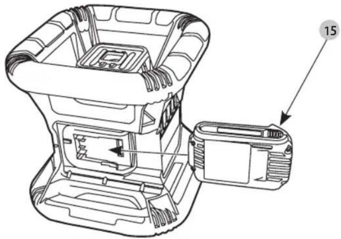
Installing the 18V DEWALT Battery Pack
- Position the fully-charged 18V DEWALT battery pack so the release button (Figure ⑤ 15) is facing away from you and to the right.
- Press and hold down the release button on the battery pack.
- Slide the battery pack all the way into the track on the side of the laser.
- Release the button on the battery pack.
Removing the Battery Pack
- Press and hold the release button on the battery pack.
- Slide the battery pack out of the track on the laser.
- Release the button on the battery pack.
- To recharge the battery pack, insert it into the charger, as described in the Battery Safety Manual.
WARNING: Batteries can explode or leak, and can cause injury or fire. To reduce this risk, follow the instructions in the Battery Safety Manual.
Storing Battery Packs
- The best storage place is one that is cool and dry, and away from direct sunlight and excess heat or cold.
- Long storage will not harm the battery pack or charger. Under proper conditions, they can be stored for 5 years or more.
SAVE THESE INSTRUCTIONS FOR FUTURE USE
User Safety
Personal Safety
- Stay alert, watch what you are doing, and use common sense when operating a laser product. Do not use the tool while tired or under the influence of drugs, alcohol, or medication. A moment of inattention while operating laser products may result in serious personal injury.
- Use appropriate personal protective equipment, including eye protection when working in a construction environment.
Tool Use and Care
- Do not use the tool if the switch does not turn it on or off. Any tool that cannot be controlled with the switch is dangerous and must be repaired.
- Store idle laser products out of the reach of children and do not allow persons unfamiliar with the laser product or these instructions to operate the laser product. Laser products are dangerous in the hands of untrained users.
- Use only accessories that are recommended by the manufacturer for your model. Accessories that may be suitable for one tool, may become hazardous when used with another tool.
ENGLISH
Operation
Operating Tips
- To extend battery life per charge, turn the laser off when it is not in use.
- To ensure the accuracy of your work, check the laser calibration often. Refer to Calibrating the Laser.
- Before attempting to use the laser, make sure the tool is positioned on a relatively smooth, secure surface.
- Always mark the center of the laser line or dot. If you mark different parts of the beam at different times you will introduce error into your measurements.
- To increase working distance and accuracy, set up the laser in the middle of your working area.
- When attaching to a tripod or wall, mount the laser securely.
- When working indoors, a slow rotary head speed will produce a visibly brighter line, a faster rotary head speed will produce a visibly solid line.
- To increase beam visibility, wear Laser Enhancement Glass es and/or use a Laser Target Card to help find the beam.
- Extreme temperature changes can cause movement or shifting of building structures, metal tripods, equipment, etc., which can effect accuracy. Check your accuracy often while working.
- When working with the DEWALT Digital Laser Detector, set the laser's rotation speed to the fastest setting.
- If the laser is dropped or has suffered a sharp blow, have the calibration system checked by a qualified service center before using the laser.
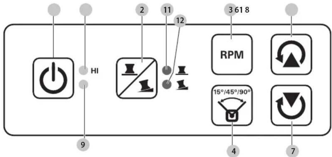
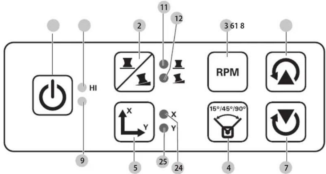
Control Panel (Fig. A, B)
The laser is primarily controlled by the power button 1, the mode button 2, the speed button 3 and the scan mode button 4. These features are then modified when used with either the Axis selection button 5 (DCE079R/DCE079G in Slope mode only), or the two direction/elevation adjustment buttons 6 and 7.
The direction/elevation adjustment buttons control the rotational direction of the laser head as well as adjust the elevation of the beam when the unit is in slope mode. These buttons can also be used to incrementally rotate the beam when the unit is in Scan mode.
The buttons on the DCE074R control panel, DCE079R/G control panel, and the DCE079R/G Remote keypad all work the same, unless otherwise indicated.
Power Button

The Power button is used to turn the laser unit on and off.
- To power ON the DCE074R or DCE079R/G laser unit, press the Power button once.
- To completely power OFF the DCE074R or DCE079R/G laser unit, press the power button for 3 sec.
Speed/Rotation Button

The speed button 3 is used to adjust the rotation speed of the laser beam through its 4 preset speeds (150, 300, 600, and 1200 RPM).
Scan Mode Button

The scan mode button 4 is used to make the laser head sweep back and forth, creating a short, bright laser line. This short line is much brighter and more visible than when the unit is in full rotation mode.
Using Scan Mode
- To enter Scan Mode, push and release the scan mode button 4. To cycle through the scan angles, continue to press the button until you reach the desired angle.
- The direction of the scan zone can be controlled with the arrow buttons 6 and 7.
Slope Mode Button

• To activate Slope Mode press the slope mode button 2.
- To return to self-leveling mode and re-engage full self-leveling, press and hold the mode button 2 again.
Setting the Slope Direction
When Slope Mode is activated, the unit automatically engages the X-Axis. This allows you to slope the laser in the direction of the X-Axis, as indicated by the "gunsights" on the rollcage.
The LED light 11 or 12 indicates the current slope direction.
DCE079R/G only: In certain situations, it may be desirable to slope the laser in the Y-axis. The direction of Slope Mode can be changed back and forth between the Y-axis and the X-axis by pressing the X-Y axis button 5. The selected axis is identified by LED light 24 or 25.
Setting the Amount of Slope
- Turn on Slope Mode.
- Select the desired axis.
- Use the Arrow buttons (Fig. ⑧, 6 and 7) to tilt the laser rotor head up and down.
- Each quick press of an Arrow button will move the slope by 0.01° (1/16" @ 30ft. or 1.6mm @ 10m).
- If you press and hold an Arrow button between 2 sec-10 sec, the slope will move from .0.01°/sec to 0.2°/sec.
- If you press and hold an Arrow button longer than 10 sec, the slope will move 0.2^ / sec .
Arrow Buttons (Fig. Ⓑ, Ⓡ)

The arrow buttons (B 6 and 7) are used for different functions depending on the operating mode of the laser unit.
- In Self-Leveling Horizontal Mode, the arrow buttons rotate the direction of the laser beam clockwise or counterclockwise during rotation, or adjust the position of the laser beam clockwise or counter-clockwise during Scan Mode.
- In Self-Leveling Vertical Mode, the arrow buttons rotate the direction of the laser beam clockwise or counterclockwise during rotation, or adjust the position of the laser beam clockwise or counter-clockwise during Scan Mode.
- In Slope Mode, the arrow buttons are used to tilt the laser head.
Turning the Laser On (Fig. E, B)
- Insert the fully charged 18V battery pack as shown in Figure E.
- Gently press the power button 1 to power ON the laser.

- The power LED indicator light 9 will illuminate
- Self-leveling mode is activated automatically and the laser unit will self-level. Once the laser unit is level, the beam will rotate once at 600 RPM in the clockwise direction.
-
After 10 sec., Hi Mode (Anti-Drift) is activated automatically and the Hi LED 8 will illuminate.
-
Press the speed/rotation button 3 to adjust the rotation speed. The direction can be changed using buttons 6 and 7.
- Press the Scan button 4 to set the laser to scan in 0°, 15°, 45°, or 90° degree mode.
If you turn ON Slope Mode, the Slope LED 12 will light. If using X-axis leveling, the X-axis LED 24 will light, or if using Y-axis leveling, the Y-axis LED 25 will light instead.
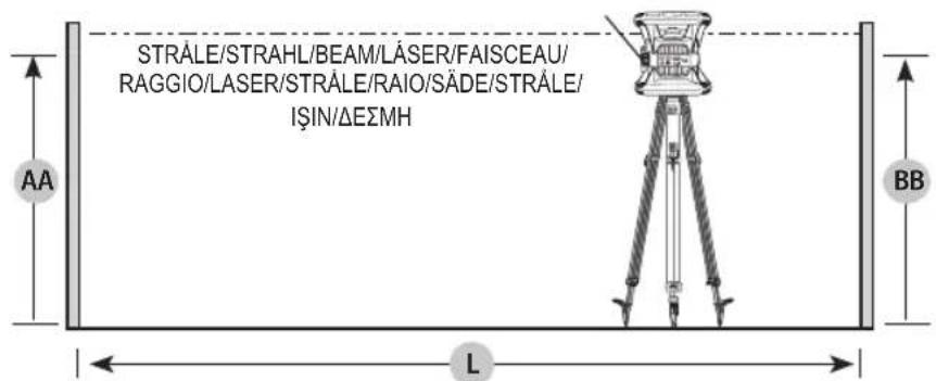
Calibrating the Laser (Fig. O, P)
Field calibration checks should be done frequently. This section provides instructions for performing simple field calibration checks of your DEWALT Rotary Laser. Field calibration checks do not calibrate the laser. That is, these checks do not correct errors in the leveling or plumbing capability of the laser. Instead, the checks indicate whether or not the laser is providing a correct level and plumb line. These checks cannot take the place of professional calibration performed by a DEWALT service center.
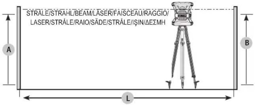
Level Calibration Check (X-axis)
- Set up a tripod between two walls that are at least 50 feet apart. The exact location of the tripod is not critical.
- Mount the laser unit on the tripod so that the X-axis points directly toward one of the walls.
- Turn the laser unit on and allow it to self-level.
- Mark and measure points A and B on the walls as shown in Figure O.
- Turn the entire laser unit 180^ so the X-axis points directly toward the opposite wall.
- Allow the laser unit to self-level, and mark and measure points AA and BB on the walls as shown in Figure P.
- Calculate the total error using the equation:
$$ \text { Total Error } = (\mathbf {A} \mathbf {A} - \mathbf {A}) - (\mathbf {B} \mathbf {B} - \mathbf {B}) $$
- Compare total error to the allowable limits shown in the following table.
| Distance Between Walls | Allowable Error DCE074R | Allowable Error DCE079R/G |
| 15m 3mm 1 | .5mm | |
| 20m 4mm 2 | mm | |
| 25m 5mm 2 | .5mm | |
| 30m 6mm 3 | mm |
Level Calibration Check (Y-axis)
Repeat the procedure above, but with the laser unit positioned so the Y-axis is pointed directly toward the walls.
Plumb Error Check (Fig. Q)
- Using a standard plumb bob as a reference, mark the top and bottom of a wall. (Be sure to mark the wall and not the floor and ceiling.)
- Position the rotary laser securely on the floor approximately 3' (1 m) from the wall.
- Turn the laser on, and point the dot at the mark on the bottom of the wall. Then, using the up/down arrows on the remote control, rotate the dot upwards. If the center of the dot scans over the mark on the top of the wall, the laser is properly calibrated.
NOTE: This check should be done with a wall no shorter than the tallest wall for which this laser will be used.
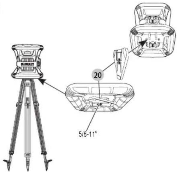
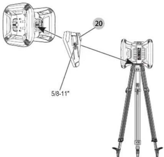
Using the Laser on a Tripod (Fig. ©)
- Position the tripod securely and set it to the desired height.
- Make sure that the top of the tripod is roughly level. The laser will self-level only if the top of the tripod is within ±5^ of level. If the laser is set up too far out of level, it will beep when it reaches the limit of its leveling range. No damage will be done to the laser, but it will not operate in an “out of level” condition.
ENGLISH
- Secure the laser to the tripod by attaching the tripod adapter 20 as shown in Figure © to the laser body. The adapter may be assembled to the bottom for level mode or to the side for plumb mode. Place the assembly on the tripod and screw the threaded knob on the tripod into the female thread on the tripod adapter.
NOTE: Be sure that the tripod you are working with has a 5/8"-11 threaded screw to ensure secure mounting.
- Turn the laser on and adjust the rotation speed and controls as desired.
Using the Laser on a Floor (Fig. ①)
The laser level can be positioned directly on the floor for leveling and plumbing applications such as framing walls.
-
Place the laser on a relatively smooth and level surface where it will not be disturbed.
-
Position the laser for a level or plumb setting as shown.
-
Turn the laser on and adjust the rotation speed and controls as desired.
NOTE: The laser will be easier to set up for wall applications if the rotation speed is set to 0 RPM and if the remote control is used to line up the laser with control marks. The remote allows one person to set up the laser.
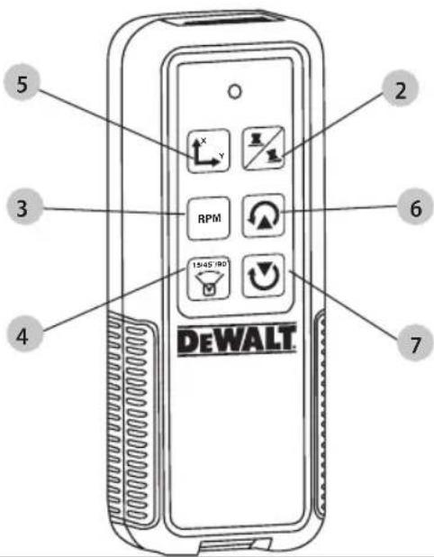
Using the DCE079R/G Remote
The remote control allows one person to operate and set up the laser from a distance. The LED light on the remote control indicates a signal is being transmitted from the DCE079R/G laser unit. You can use all the buttons on the keypad to control that laser unit.
If your DCE079R/G laser unit was stamped on or after 2016-49-NZ, you can use the Remote to completely power OFF the laser unit.
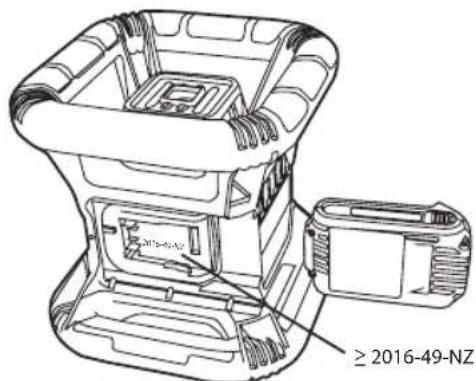
To completely power OFF a DCE079R/G laser unit (stamped on or after 2016-49-NZ) using the Remote keypad, press the X-Y axis button 14 and the MODE button 13 simultaneously.
Specifications
| DCE074R DCE079R DCE079G | |||
| Voltage 18V | DC | 18V_DC | 18V_DC |
| Type 1 1 1 | |||
| Laser power < 1mW < 1mW < 1mW | |||
| Laser class 2 2 2 | |||
| Wavelength 630 ~ 680 | nm | 630 ~ 680 nm | 515 ~ 530 |
| 630 ~ 680 | |||
| Rotation Speed (RPM) 150, 300, 600, 1200 | 150, 300, 600, 1200 | 150, 300, 600, 1200 | |
| Indoor Visible Range | 45m | 60m | 80m |
| Range with Detector | 450m | 600m | 600m |
| Leveling Accuracy (@ 600 RPM) | ± 3 mm per 30 m | ± 1,5 mm per 30 m | ± 1,5 mm per 30 m |
| Self-leveling range | ± 5° | ± 5° | ± 5° |
| Operating temperature | -5 °C - 50 °C | -5 °C - 50 °C | -5 °C - 50 °C |
| Storage Temperature | -20 °C - 70 °C | -20 °C - 70 °C | -20 °C - 70 °C |
| Receptacle thread | 5/8"-11 TPI | 5/8"-11 TPI | 5/8"-11 TPI |
| Weight (without battery pack) | 4.5kg 4.5kg | 4.5kg | |
Accessories
Recommended accessories for use with your tool are available for purchase at your factory-owned local service center.

WARNING: Since accessories, other than those offered by DEWALT, have not been tested with this product, use of such accessories with this tool could be hazardous. To reduce the risk of injury, only DEWALT, recommended accessories should be used with this product.
If you need assistance in locating any accessory, please visit our website www.2helpU.com.
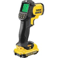
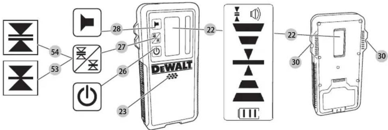
Digital Laser Detector (Fig. ①—⑨)
Some laser kits include a DEWALT Digital Laser Detector. The DEWALT Digital Laser Detector allows you to locate a laser beam emitted by a rotary laser in bright light conditions or over long distances. The detector can be used in both indoor and outdoor situations where it is difficult to see the laser beam.
The detector is not for use with non-rotating lasers but is compatible with most rotary red-beam (DW0743R) and green beam (DW0743G) lasers. It can be set to indicate the location of the beam to either the nearest 1/8" (3 mm) or the nearest 1/25" (1 mm). The detector gives both visual signals through the display window 22 and audio signals through the speaker 23 to indicate the location of the laser beam.
The DEWALT Digital Laser Detector can be used with or without the detector clamp. When used with the clamp, the detector can be positioned on a grade rod, leveling pole, stud or post.
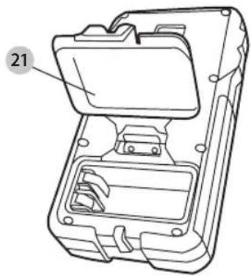
Installing a Battery in the Detector (Fig. ①)
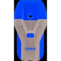
The Digital Laser Detector is powered by a 9 volt battery. To install the battery provided, lift up on the battery compartment cover 21. Place the 9 volt battery in the compartment, aligning the battery as shown.
Detector Controls (Fig. ①)
The detector is controlled by the power button 26 and the accuracy mode button 27.
When the power button is pushed once, the detector is turned on. The top of the display window shows the accuracy icon 27, and the volume icon 28. To decrease the volume of the audible signal that the detector emits when it senses a laser beam, push the button again; one of the half circles next to the horn icon will disappear. To turn off the audible signal push the button a third time; the volume icon will dissapear. The DEWALT Digital Laser Detector also has an auto shut-off feature. If a rotary laser beam does not strike the beam detection window, or if no buttons are pressed, the detector will shut itself off in about 30 minutes.
When the detector is on, the top of the window shows an accuracy mode icon. Either the 1 mm accuracy mode icon 53 will appear, or the 3 mm accuracy mode icon 54 will appear. When the 1 mm accuracy mode icon appears, it indicates that the detector will give an "on grade" reading only when the laser beam is on grade or no more than 1 mm above or below it. When the 3 mm accuracy mode icon appears, it indicates that the detector will give an "on grade" reading when the laser beam is on grade or approximately 3 mm above or below it. Push the accuracy mode button 27 once to change the accuracy mode.
Detector Operation (Fig. ①, ②)
- Set up and position the rotary laser that you will be using according to the manufacturer's directions. Turn the laser on and make sure that the laser is rotating and emitting a laser beam. NOTE: This detector has been designed to be used only with a rotating laser. The detector will not work with a stationary beam laser level.
- Turn the detector on by pressing the power/volume button 26.
- Adjust the volume as desired as described in the Detector Controls.
- Position the detector so that the detector window 22 is facing the laser beam produced by the rotary laser. Move the detector up or down within the approximate area of the beam, until you have centered the detector. For information about the display window indicators and the audible signal indicators, refer to the table titled Indicators (Fig. ①).
- Use the marking notches 30 to accurately mark the position of the laser beam.
Detector Cleaning and Storage
- Dirt and grease may be removed from the exterior of the detector using a cloth or soft, non-metallic brush.
- The DEWALT Digital Laser Detector is waterproof. If you should drop the detector in mud, wet concrete, or a similar substance, simply hose the detector off. Do not use high pressure water, e.g., from a pressure washer.
- The best storage place is one that is cool and dry-away from direct sunlight and excess heat or cold.
Detector Service
Except for batteries, there are no user serviceable parts in the Digital Laser Detector. Do not disassemble the unit. Unauthorized tampering with the laser detector will void all warranties.
Detector Troubleshooting
The detector will not turn on.
- Press and release the power/volume button.
- Check to see that the battery is in place and in the proper position.
- If the detector is very cold, allow it to warm up in a heated area.
- Replace the 9 volt battery. Turn the unit on.
- If the detector still does not turn on, take the detector to a DEWALT service center.
The detector's speaker makes no sound.
- Ensure that the detector is on.
- Press the power/volume button. It will toggle from high, to low, to mute.
- Ensure that the rotary laser is spinning and that it is emitting a laser beam.
- If the detector is still not making any sound, take it to a DEWALT service center.
The detector does not respond to a stationary laser beam.
The DEWALT Digital Laser Detector has been designed to work only with rotary lasers.
The detector gives off a tone but the LCD display window does not function.
- If the detector is very cold, allow it to warm up in a heated area.
- If the LCD display window is still not functioning, take the detector to a DEWALT service center.
ENGLISH
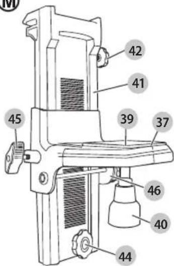
Mounting Bracket (Fig. M, N)
Some laser kits include a Wall Mount. It can be used for attaching the tool to track or ceiling angle and to aid in acoustical ceiling installation. Follow the directions below for using the wall mount.
CAUTION: Before attaching the laser level to wall track or ceiling angle, be sure that the track or angle is properly secured.
- Place the laser on the mounting base 37 aligning the 5/8–11 screw hole on the tripod adapter (20, Fig. ©) attached to the bottom of the laser with the hole 39 in the mounting base. Turn the mounting knob 40 to secure the laser.
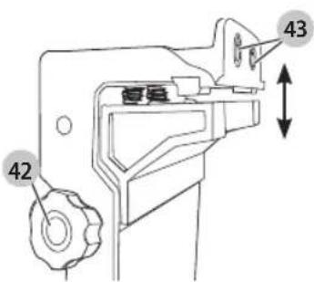
- With the wall mount measuring scale 41 facing you, loosen the wall mount clamp locking knob 42 to open the clamp jaws.
- Position the clamp jaws around the wall track or ceiling angle and tighten the wall mount clamp locking knob 42 to close the clamp jaws onto the track. Be sure that the wall mount clamp locking knob is securely tightened before proceeding.
CAUTION: Always use a ceiling wire hanger or equivalent material, in addition to the wall mount clamp locking knob, to help secure the laser level while mounting it to a wall. Thread the wire through the handle of the laser level. DO NOT thread the wire through the protective metal cage. Additionally, screws may be used to fasten the wall mount directly to the wall as a back up. Screw holes 43 are located at the top of the wall mount.
-
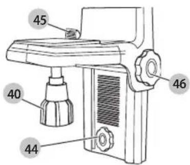
Using the base leveling knob 44 approximate a level position from the wall.
-
The tool can be adjusted up and down to the desired offset height for working. To change the height, loosen the locking knob 45 located on the left of the wall mount. Support the mounting base when adjusting the height.
-
Turn the adjustment knob 46, located to the right of the wall mount, to move the laser level up and down to set your height. Use the wall mount measuring scale 41 to pinpoint your mark.
NOTE: It may be helpful to turn the power on and turn the rotary head so that it puts a dot on one of the laser scales. The DeWALT target card is marked at 38mm, therefore, it may be easiest to set the offset of the laser to 38mm below the track.
- Once you have positioned the laser at the desired height, tighten the locking knob 45 to maintain this position.
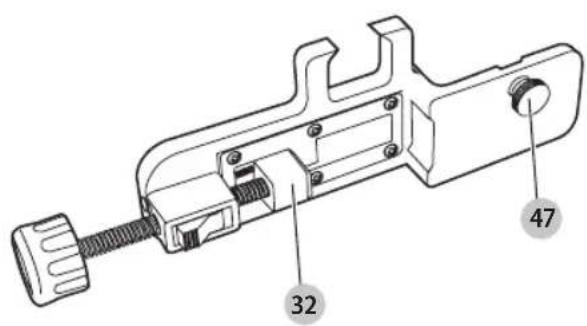
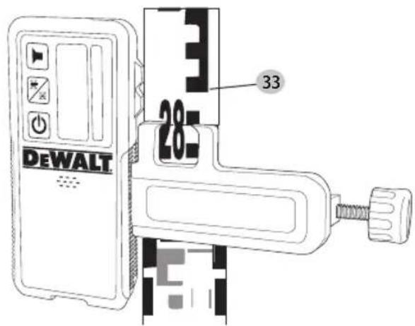
Mounting on a Grade Rod (Fig.⑨)
To secure your detector to a grade rod, first attach the detector to the clamp using the 1/4"-20 threaded knob 47 on the back of the clamp. Slide the tracks 32 on the clamp around the rail 33 on the grade rod.
- Position the detector at the height needed and turn the clamp knob clockwise to tighten the jaws of the clamp around the grade securing the clamp on the rod.
- To make adjustments in height, slightly loosen the clamp, reposition and retighten.
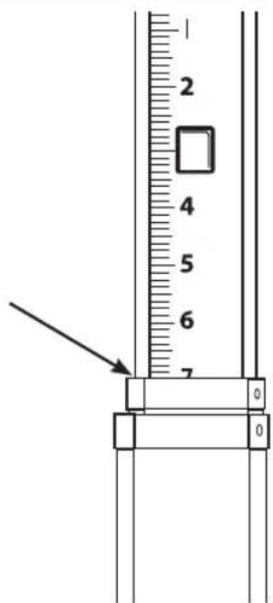
Construction Grade Rod (Fig. ①)
DANGER: NEVER attempt to use a grade rod in a standard or near overhanging electric wires. Death or serious personal injury will occur.
Some laser kits include a grade rod. The DEWALT Grade Rod is marked with measurement scales on both sides and is constructed in telescoping sections. A spring-loaded button actuates a lock to hold the grade rod at various lengths.
The front of the grade rod has the measurement scale starting at the bottom. Use this for measuring from the ground up when grading or leveling jobs.
The back of the grade rod is designed to measure the height of ceilings, joists, etc. Fully extend the top section of the grade rod until the button locks into the previous section. Extend that section either until it locks into the adjacent section or until the grade rod touches the ceiling or joist. The height is read where the last extended section exits the previous lower section, as shown in Figure ①.
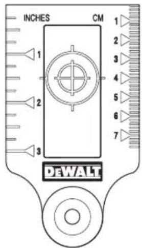
Target Card (Fig. ©)
Some laser kits include a Laser Target Card to aid in locating and marking the laser beam. The target card enhances the visibility of the laser beam as the beam crosses over the card. The card is marked with standard and metric scales. The laser beam passes through the red plastic and reflects off of the reflective tape on the reverse side. The magnet at the top of the card is designed to hold the target card to ceiling track or steel studs to determine plumb and level positions. For best performance when using the Target Card, the DEWALT logo should be facing you.
Laser Enhancement Glasses (Fig. ⑤)
Some laser kits include a pair of Laser En hancement Glasses. These glasses improve the visibility of the laser beam under bright light conditions or over long distances when the laser is used for interior applications. These glasses are not required to operate the laser.
CAUTION: These glasses are not ANSI approved sensory glasses and should not be worn while operating other tools. These glasses do not keep the laser beam from entering your eyes.
DANGER: To reduce the risk of serious personal injury, no store directly into the laser beam, with or without these glasses.
Maintenance
- Under some conditions, the glass lens may collect some dirt or debris. This will affect beam quality and operating range. The lens should be cleaned with a cotton swab moistened with water.
- The flexible rubber shield can be cleaned with a wet lint-free cloth such as a cotton cloth. USE WATER ONLY — DO NOT use cleansers or solvents. Allow the unit to air dry before storing.
- To maintain the accuracy of your work, check the calibration of the laser often. Refer to Calibrating the Laser.
- Calibration checks and other maintenance repairs can be performed by DEWALT service centers. Two free calibration checks are included under the DEWALT One Year Free Service Con tract.
- When the laser is not in use, store it in the kit box provided.
- Do not store your laser in the kit box if the laser is wet. Dry exterior parts with a soft, dry cloth and allow the laser to air dry.
- Do not store your laser at temperatures below -18°C or above 41°C.
WARNING: Never use solvents or other harsh chemicals for cleaning the non-metallic parts of the tool. These chemicals may weaken the materials used in these parts. Use a cloth dampened only with water and mild soap. Never let any liquid get inside the unit; never immerse any part of the unit into a liquid. Never use compressed air to clean the laser.
Troubleshooting
Height of Instrument Alert
The DCE074R and DCE079R/G have a built-in alarm feature that alerts the operator if the unit is disturbed after the unit has self-leveled. The laser unit will stop rotating, the control panel LED indicator light will flash, and the beeper will sound.
Turning the Laser Off
Press the the power button for 3 sec to turn the laser off. The power LED indicator light will no longer be illuminated.
To Reset The Laser Unit for Continued Use
Turn the unit off and back on again using the power button on the laser unit control panel.
NOTE: Always recheck the laser setup after the Height of Instrument Alert (Hi mode) has triggered.
Service and Repairs
NOTE: Disassembling the laser level will void all warranties on the product.
To assure product SAFETY and RELIABILITY, repairs, maintenance and adjustment should be performed by authorized service centers. Service or maintenance performed by unqualified personnel may result in a risk of injury. To locate your nearest DEWALT service center, visit our website: www.2helpU.com.
Protecting the Environment
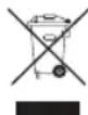
Separate collection. Products and batteries marked with this symbol must not be disposed of with normal household waste.
Products and batteries contain materials that can be recovered or recycled reducing the demand for raw materials. Please recycle electrical products and batteries according to local provisions. Further information is available at www.2helpU.com.

Batteries
When disposing batteries, think of the protection of the environment. Check with your local authorities for an environmentally safe way of battery disposal.
ESPAÑOL
natural_image
Technical line drawing of a mechanical component with three directional arrows indicating flow or force directions (no text or symbols present)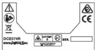
ITALIANO
Bedieningspaneel (afb. Ⓐ, Ⓑ)
natural_image
Technical line drawing of a mechanical housing with internal components and directional arrows indicating flow or force (no text or symbols)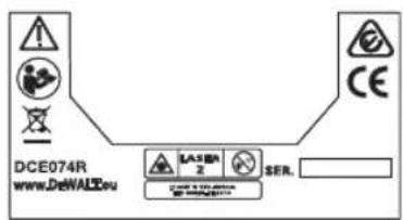

NORSK
natural_image
Technical line drawing of a mechanical component with three directional arrows indicating flow or direction (no text or symbols present)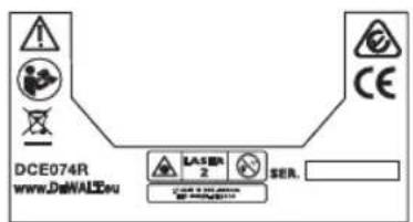

SVENSKA
natural_image
Technical line drawing of a mechanical housing or enclosure component (no text or symbols)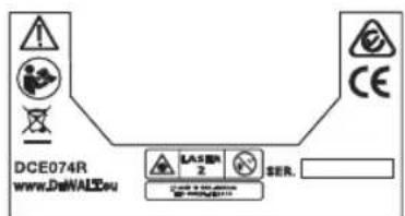
TÜRKÇE
© 2018 DeWalt Industrial Tool Co.,
DEWALT Europe, DEWALT D-65510 Idstein,
Germany 65509
Made in China
N602824
May 2018