
CoolAir SP 950C - Air Conditioning DOMETIC - Free user manual and instructions
Find the device manual for free CoolAir SP 950C DOMETIC in PDF.
| Product type | Auxiliary air conditioner for truck cabin |
| Brand | Dometic |
| Model | CoolAir SP 950C |
| Refrigerant | R-134a (120 g, CO2 equivalent 0.1716 t, GWP 1430) |
| Max. cooling power | 850 W |
| Supply voltage | 24 Vdc (22.5 – 30 Vdc) |
| Max. current consumption | 22 A |
| Operating temperature range | 0 °C to +43 °C |
| Battery protection | Configurable automatic shutdown in case of undervoltage |
| Operating modes | 3 power levels (low, medium, high), automatic mode, programmable timer (10-120 min) |
| Remote control | Included, allows on/standby, settings |
| Digital display | Set temperature, mode, error codes |
| Maintenance | External cleaning with damp cloth, check seals and hoses |
| Safety | Overvoltage protection (HI), undervoltage (LO), excessive tilt (---) |
| Warranty | Legal warranty (see manual) |
| Recycling | Recyclable packaging, batteries to be returned |
Frequently Asked Questions - CoolAir SP 950C DOMETIC
User questions about CoolAir SP 950C DOMETIC
0 question about this device. Answer the ones you know or ask your own.
Ask a new question about this device
Download the instructions for your Air Conditioning in PDF format for free! Find your manual CoolAir SP 950C - DOMETIC and take your electronic device back in hand. On this page are published all the documents necessary for the use of your device. CoolAir SP 950C by DOMETIC.
USER MANUAL CoolAir SP 950C DOMETIC
natural_image
White portable air conditioner unit with four circular venters and a digital display (no visible text or symbols)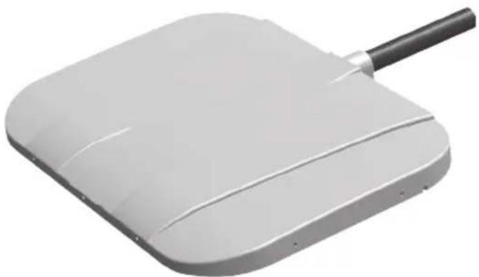
natural_image
3D rendering of a white rectangular electronic device with a black handle and curved surface (no text or symbols visible)SP950I, SP950T
EN Parking cooler
Operating manual....6
DE Standklimaanlage
Please read this instruction manual carefully before first use, and store it in a safe place. If you pass on the product to another person, hand over this instruction manual along with it.
Contents
1 Explanation of symbols....7
2 Safety instructions....7
3 Target group 9
4 Intended use 9
5 Technical description ..... 10
6 Operation 11
7 Using the parking cooler 13
8 Display messages....19
9 Maintenance and care ....21
10 Guarantee 22
11 Disposal.... 22
12 Technical data 23
1 Explanation of symbols

WARNING!
Safety instruction: Failure to observe this instruction can cause fatal or serious injury.

CAUTION!
Safety instruction: Failure to observe this instruction can lead to injury.

NOTICE!
Failure to observe this instruction can cause material damage and impair the function of the product.

NOTE
Supplementary information for operating the product.
2 Safety instructions
The manufacturer accepts no liability for damage in the following cases:
- Damage to the product resulting from mechanical influences and excess voltage
• Alterations to the product without express permission from the manufacturer - Use for purposes other than those described in the operating manual
2.1 Using the device

WARNING!
- Only use the parking cooler for the purpose specified by the manufacturer and do not make any alterations or structural changes to the device.
- Do not use the parking cooler if it is visibly damaged.
- Installation and repairs to the parking cooler may only be carried out by qualified personnel who are familiar with the risks involved and the relevant regulations. Improper repairs can lead to considerable hazards.
For repair service, please contact the service centre in your country (addresses on the back).
- People (including children) whose physical, sensory or mental capacities prevent them from using this device safely may not be allowed to operate it without the supervision of a responsible adult.
• Electrical devices are not toys.
Always keep and use the appliance out of the reach of children.
- Children must be supervised to ensure that they do not play with the device.
- Make sure no combustible objects are stored or installed near the air outlet. A distance of at least 50 cm must be kept.
- Do not use the parking cooler near flammable fluids and gases.
- Do not undo the upper cover of the parking cooler in the event of a fire. Use approved extinguishing agents instead. Do not use water to extinguish fires.
- Do not reach into air grilles or ventilation nozzles or insert any foreign objects into the system.

CAUTION!
- Disconnect all power supply lines when working on the parking cooler (cleaning, maintenance etc).

NOTICE!
- The parking cooler is not suitable for use in agricultural or construction vehicles.
- Vehicles with SP950 parking cooler with SP950T roof evaporator unit may only be cleaned in automatic car washes where the top brush can be switched off manually.
- Switch the parking cooler off before tilting the cab for maintenance.
- Switch off the parking cooler before using automatic washing equipment (automatic car washes etc.) to clean the vehicle.
- Always manually drain the condensation from the system before maintenance or tilting the cab (chapter "Extracting condensation (SP950 with SP950T roof evaporator unit only)" on page 17).
- Do not operate the parking cooler if the ambient temperature is below 0^ C.
- Please inform your vehicle manufacturer if the height entered in your vehicle documents needs to be altered due to the installation of the parking cooler.
2.2 Operating the device safely

NOTICE!
- Do not insert foreign objects into the system.

NOTE
- In order for the condensation from the evaporator unit to drain off automatically, the angle to the side may not exceed 5^ during operation.
- In order to protect the compressor, the angle towards the front may not exceed 10^ during operation. The compressor will otherwise be switched off. After 5 minutes, the entire system is switched off.
3 Target group
The information on the device (operating instructions, handling the device, safety instructions etc.) is intended for the user of the parking cooler.
4 Intended use
The parking cooler is used to supply the interior of the driver's cab with cool and dehumidified air.
The system is designed for stationary use. It can be used while driving.
The parking cooler is not suitable for use in agricultural or construction vehicles.

NOTE
Only install the parking cooler using the manufacturer's assembly kit.
5 Technical description
The parking cooler can be used for variable air conditioning inside the vehicle. The air in the interior is guided into the system through the intake grille, cooled, dried and conveyed back into the interior through the blower nozzles. The system is operated using the control panel or the remote control.

NOTE
The parking cooler can lower the temperature within the vehicle to a certain level. The temperature depends on the type of vehicle, the ambient temperature and the cooling capacity of your parking cooler. For the cooling capacity of your parking cooler, see chapter “Technical data” on page 23.
The system is fitted with a battery monitor. If the system is operated when the vehicle ignition is switched off, the parking cooler switches off automatically as soon as the supply voltage falls below a set level.
The refrigerant circuit of the parking cooler consists of four main components:
- Compressor The compressor draws in the R-134a refrigerant and compresses it. This raises the pressure and therefore the temperature of the refrigerant.
- Condenser The built-in condenser works like a cooler or heat exchanger. The air flowing past absorbs the heat and the hot refrigerant gas cools down and becomes liquid.
- Capillary tube The capillary tube reduces the refrigerant from the higher condenser pressure to the lower vaporisation pressure.
- Vaporiser The vaporiser cools down the air flowing past and dehumidifies it. The refrigerant absorbs the heat and vaporises. The cooled air is distributed within the vehicle through an air outlet unit.
6 O p e r a t i o n
6.1 Device elements
The parking cooler has the following controls:
No. in fig. 1, page 3 Explanation
1 Blower nozzles
2 Intake grille
3 Control panel
6.2 Control panel
The following control and display elements are available on the control panel for operating the system:
| No. in fig. 2, page 3 | Meaning |
| 1 | 1 button |
| 2 Fault LED (red)The LED indicates system malfunctions. | |
| 3 Compressor LED (yellow)The LED lights up when the compressor is operating. | |
| 4 | buttonUse the button to switch between operating modes 1, 2, 3 or Automatic and the Timer function. |
| 5 Digital displayShows:the selected operating modefor operating mode 1for operating mode 2for operating mode 3for automatic mode000 for the timer functionSelected temperature in °C (target) | |
| 6 + buttonThe + button increases the temperature by 1 °C or the timer running time by 10 minutes. | |
| 7 - buttonThe - button decreases the temperature by 1 °C or the timer running time by 10 minutes. | |
| 8 POWER LED (blue)The LED indicates that the system is switched on. | |
| 9 Infrared receiver (for the remote control) | |
6.3 Remote control
The remote control is equipped with the following control elements for operating the system:
| No. in fig. 3, page 4 | Meaning |
| 1 | buttonThe system can be switched between active and standby modes. |
| 2 | buttonThe button decreases the temperature by 1 °C or the timer running time by 10 minutes. |
| 3 | buttonThe button increases the temperature by 1 °C or the timer running time by 10 minutes. |
| 4 | buttonThe operating button switches to the next mode down. |
| 5 | buttonThe operating button switches to the next mode up. |
7 Using the parking cooler

NOTICE!
- The manufacturer assumes no liability for non-observance of this operating manual, in particular for any consequential damage, especially consequential damage caused by failure of the parking cooler.
- Do not insert foreign objects into the system.
7.1 Tip for improved use

NOTE
The SP950 is designed as a stationary air conditioner for relaxing rest periods. It can be used while driving, does not however replace the engine-powered vehicle air conditioning system.
Observe the following instructions for use to ensure your CoolAir parking cooler is used efficiently:
It is recommended that you:
- Park your vehicle in the shade when possible.
• Shade your vehicle when possible. - If you do not have a vehicle air conditioning system, air out your vehicle well before using the parking cooler. You should always cool down the vehicle interior before a rest period using the vehicle air conditioning system.
- Keep doors and windows closed.
- Avoid any heat sources in the vehicle.
- Reduce the power consumed by other devices to ensure the maximum possible operating time of the parking cooler.
- Select a suitable temperature and operating mode.
- Make sure that the blower nozzles (fig. 1 1, page 3) and the intake grille (fig. 1 2, page 3) are not covered by cloth, paper or other objects.
Always observe the following:
- If you would like the parking cooler to match the colour of your vehicle, only paint the upper shell casing of the parking cooler.
Only paint this when it has been removed. Use light colours when possible. - Wash your vehicle regularly, as dirty driver's cabs heat up more quickly.
- Make sure that the performance of the parking cooler is not affected by other sources of heat (e.g. waste heat from cold machines).
How to actively care for your parking cooler
- Perform regular visual checks of the seals, the upper shell casing and the grill, ideally before the season starts.
- If necessary, remove any dirt and leaves from the system.
7.2 Switching on the parking cooler

NOTICE!
Never close all of the air nozzles of the parking cooler simultaneously. The device would ice up inside.

NOTE
The first time the parking cooler is used, there may be a slight smell. This is normal and soon goes away.
▶With the system switched off, press the button.

NOTE
If you completely switch off the parking cooler, it can only be switched on again using the control panel. The system can only be switched on using the remote control if it is in standby mode. If the system is not going to be used for a lengthy period, switch it off completely so that the battery is not wasted supplying standby power.
√The fan starts at low speed.
√ The Power LED (fig. 2 8, page 3) lights up.
√ The digital display (fig. 2 5, page 3) shows the target temperature in °C and the operating mode (e.g. A20 for automatic mode + temperature 20 °C).

NOTE
The compressor is switched on after a delay of approx. 90 seconds.
7.3 Selecting the temperature
You can select temperatures between 17^ C and 30^ C.
▶ Press + or - on the control panel or ⏻+ or ⏻- on the remote control to set the temperature in 1 °C increments.
√ The digital display (fig. 2 5, page 3) shows the operating mode and the selected temperature in °C.

NOTE
If mode I or II fails to achieve the selected temperature, switch to the next mode up or to automatic mode.
7.4 Selecting the operating mode
You can choose between four operating modes and the timer function:
| Operating mode | Display message | Explanation |
| 1 Lowest output level – the fans run at the lowest level. | ||
| 2 Medium output level – the fan runs at the medium level. | ||
| 3 Highest output level – the fan runs at the highest level. | ||
| Automatic | R | The system automatically selects the optimum fan speed to reach the set temperature most efficiently. |
| Timer function | 000Pre-selection of running time from 10 to 120 minutes.Alternating display for operating mode and remaining running time. | |
▶ Press the ⏻ button on the control panel or the ⏻+ or ⏻- button on the remote control to select the mode.
√ The first position of the digital display (fig. 2 5, page 3) shows the selected mode.
7.5 Extracting condensation (SP950 with SP950T roof evaporator unit only)
The condensed water which accumulates due to the way the system works is automatically extracted at intervals during operation.
You can pump out the condensated water manually when necessary:

NOTE
Before winter, extract the condensed water from the system to avoid damage caused by freezing water.
▶Switch off the system.
▶ Press and hold the ⚙️ and – buttons simultaneously.
▶In addition, press the button briefly.
√ The firmware version appears in the digital display for 5 seconds.
√ 000 then appears in the digital display and the system starts the extraction process for 15 seconds.
You can now let go of the and - buttons.
√The compressor and the fan do not switch on.
√The system switches off automatically.

NOTE
To stop the extraction early press the button until the pump switches off.
If you want to tilt the driver's cab, you first need to drain the condensation manually.
▶Keep repeating this procedure until the pump starts making a clearly audible, loud noise while draining.
√There is then no more condensation left in the system.
▶Press the button until the pump switches off.

NOTICE!
Avoid prolonged dry periods as this can damage the pump (indicated by loud noise while draining).
7.6 Switching off the parking cooler
You can switch the parking cooler to standby mode or switch it off completely. Note that the parking cooler consumes power in standby mode. Therefore, switch off the SP950 parking cooler with SP950I rear panel evaporator unit whenever possible.
Due to the design, the condensation must be pumped off from the SP950 parking cooler with SP950T roof evaporator unit. Therefore, switch the SP950 parking cooler with SP950T roof evaporator unit to standby mode after use and any subsequent journey while in motion. The condensation which accumulated during and after operation is then drained off.
Switch off the parking cooler completely when it is not in use and for longer periods (e.g. over the weekend).

NOTE
You can only use the remote control to switch the parking cooler in and out of standby mode.
▶Switching to standby mode:
With the unit switched on, briefly press the button or the button on the remote control.
√ The digital display goes out, only the blue power LED lights up.
√The compressor and the fan switch off.
▶Switching the unit off completely:
With the unit switched on, press the button for 3 seconds.
√The LEDs and digital display go out.
√The fan and the compressor switch off.
8 Display messages

NOTE
When you start the vehicle or switch on several consumers at once, the display text LO may briefly appear.
8.1 Control panel warnings
The system control unit has various functions for protecting the device and the battery. If one of these protective functions has been triggered, this is shown by the following codes on the display.
| Display text | Description Cause Remedy | ||
| LO | The battery monitor has detected low voltage. The compressor switches off immediately and the fan is switched off after 20 to 30 seconds. The whole system shuts down after 2 minutes. | Connection voltage is too low. The battery capacity is not sufficient to operate the system. | ►Brief under-voltage: No action required. ►The system switches itself off: Charge the vehicle battery or check if the battery monitor has been correctly set. |
| HI | The system has detected a brief or constant over-voltage. | A brief over-voltage may occur when large electrical consumers are switched off. Constant over-voltage is the result of an incorrect connection voltage. | ►Brief over-voltage: No action required. ►If the display message “HI” remains visible for a longer period: Check the vehicle electronics. Make sure the connection voltage is less than 30 V. |
| HO | The system has detected a brief electrical overload and switches the compressor off. | The current power requirement of the compressor is too high. | ►The brief overload is compensated by the system by switching off the compressor. The compressor starts up again after a short time. |
| - - - | The system has detected a too big inclination. The compressor is switched off. 5 minutes later, the entire system will be switched off. | The compressor (driver's cab) is tilted too far. | ►Once the compressor has been returned to its normal position, the system can be switched on again. |
8.2 Control panel fault messages
The "Fault" LED (fig. 2 2, page 3) lights up if there is a fault with the parking cooler. The type of error is shown on the display by the following error codes:
| Display text | Description Cause Remedy | ||
| F01 | The compressor does not work. | Compressor overload or fault in the electricity supply to the compressor. | ▸Switch off the system.▸Switch it on again after 60 minutes.▸If the fault occurs again, contact an authorised workshop.▸Do not operate the system at ambient temperatures of below 0 °C or above 43 °C. |
| F02 | The system cannot determine the current temperature. | Room temperature sensor is not correctly connected to the parking cooler or the measured value is not within the specifications. | |
| F03 | System overload, the compressor switches off. | Thermal overload due to a defective fan or an ambient temperature that is too high. | |
| F04 | SP950 with SP950T roof evaporator unit only:The condensation water that has formed is not being discharged. | The condensation water that has formed is not being discharged, and an error message appears in the display. | The pump is clogged or defective.The condensation water hose is clogged.The float switch is defective or jammed. |
| F05 | Overload due to fan. Short circuit in condenser fan or evaporator fan. | Leave the system switched off and consult an authorised service centre. | |
| F06 | Communication problem between display unit and control unit. | Fault in the wiring. | |
9 Maintenance and care
Please observe the following tips for the maintenance and care of your parking cooler.

NOTICE!
- Do not use abrasive cleaning agents or hard objects or inflammable agents during cleaning as these can damage the appliance.
- Do not clean the parking cooler with a high-pressure cleaner. Exposure to water can damage the parking cooler.
▶ Clean the housing of the parking cooler and the outlet panel occasionally with a damp cloth.
▶Remove leaves and other dirt from the ventilation grilles of the parking cooler occasionally. Make sure you do not damage the system in the process.
▶ Check regularly that all the elements for the air conditioning unit are fastened.
▶Check regularly that the connection lines are undamaged and secure.
▶Check regularly that all the through-holes for the air conditioning unit are sealed.
SP950 with SP950T roof evaporator unit only
▶Check the seal between the parking cooler and the roof of the vehicle for cracks and other damage once a year.
SP950 with SP950I rear panel evaporator unit only
▶Clean regularly the condensation splash guard and intake filter.
If necessary, replace the condensation splash guard (fig. 4 1, page 5) and intake filter (fig. 4 2, page 5).
10 Guarantee
The statutory warranty period applies. If the product is defective, please contact the manufacturer's branch in your country (see the back of the instruction manual for the addresses) or your retailer.
For repair and guarantee processing, please include the following documents when you send in the device:
• A copy of the receipt with purchasing date
• A reason for the claim or description of the fault
11 Disposal
Place the packaging material in the appropriate recycling waste bins wherever possible.
If you wish to finally dispose of the product, ask your local recycling centre or specialist dealer for details about how to do this in accordance with the applicable disposal regulations.
11.1 Disposing of remote control batteries

Protect the environment!
Do not dispose of any batteries with general household waste.
Return defective or used batteries to your retailer or dispose of them at collection points.
12 Technical data
| CoolAir SP950 parking cooler with SP950T roof evaporator unit | |
| Cooling capacity: 850 W | |
| Voltage: | 24 V--- (22.5 V--- - 30 V---) |
| Max. current consumption: 22 A | |
| Operating temperature range: 0 to +43 °C | |
| Low voltage shutdown: Configurable | (See installation manual) |
| Refrigerant: R-134a | |
| Refrigerant quantity: 70 g | |
| CO2 equivalent: 0.1001 t | |
| Global warming potential (GWP): 1430 | |
| Dimensions (L x W x H):Evaporator unit:Condenser unit: | 577 x 779 x 182 mm156 x 346 x 490 mm |
| Weight:Evaporator unit:Condenser unit: | approx. 15 kgapprox. 12 kgCoolAir SP950 parking cooler with SP950I rear panel evaporator unit |
| Cooling capacity: 850 W | |
| Rated input voltage: 24 V--- | |
| Input voltage range: | 22.5 V--- - 30 V--- |
| Max. current consumption: 22 A | |
| Operating temperature range: 0 to +43 °C | |
| Low voltage shutdown: Configurable | (See installation manual) |
| Refrigerant: R-134a | |
| Refrigerant quantity: 60 g | |
| CO2 equivalent: 0.858 t | |
| Global warming potential (GWP): 1430 | |
| Dimensions (W x H x D):Evaporator unit:Condenser unit: | 648 x 278 x 144 mm346 x 490 x 156 mm |
| Weight:Evaporator unit(including connection lines):Condenser unit(without fastening frame): | approx. 10,5 kgapprox. 12 kg |
| SP950C | |
| Refrigerant: R-134a | |
| Refrigerant quantity: 120 g | |
| CO2equivalent: 0,1716 t | |
| Global warming potential (GWP): 1430 |
5 Description technique
Dometic Australia Pty. Ltd.
1 John Duncan Court
Varsity Lakes QLD 4227
1800212121
+61755076001
Mail: sales@dometic.com.au
AUSTRIA
Dometic Austria GmbH
Neudorferstraße 108
A-2353 Guntramsdorf
+43 2236 908070
+43 2236 90807060
Mail: info@dometic.at
BENELUX
Dometic Branch Office Belgium
Zincstraat 3
B-1500 Halle
+32 2 3598040
+32 2 3598050
Mail: info@dometic.be
BRAZIL
Dometic DO Brasil LTDA
Avenida Paulista 1754, conj. 111
SP 01310-920 Sao Paulo
+551132513352
+551132513362
Dometic Group Asia Pacific
Suites 2207-11 · 22/F · Tower 1
The Gateway · 25 Canton Road,
Tsim Sha Tsui · Kowloon
+852 2 4611386
+852 2 4665553
Mail: info@waeco.com.hk
HUNGARY
Dometic Zrt. Sales Office
Kerékgyártó u. 5.
H-1147 Budapest
+3614684400
+3614684401
Dometic Italy S.r.l.
Via Virgilio, 3
I-47122 Forlì (FC)
+39 0543 754901
+39 0543 754983
Mail: vendite@dometic.it
JAPAN
Dometic KK
Maekawa-Shibaura, Bldg. 2
2-13-9 Shibaura Minato-ku
Tokyo 108-0023
+81 3 5445 3333
+81 3 5445 3339
Mail: info@dometic.jp
MEXICO
Circuito Médicos No. 6 Local 1
Colonia Ciudad Satélite
CP 53100 Naucalpan de Juárez
Estado de México
+52 55 5374 4108
+52 55 5393 468
Mail: info@dometic.com.mx
NETHERLANDS
Dometic Benelux B.V.
Ecustraat 3
NL-4879 NP Etten-Leur
+31 76 5029000
+31765029019
Mail: info@dometic.nl
NEW ZEALAND
Dometic New Zealand Ltd.
PO Box 12011
Penrose
Auckland 1642
+6496221490
+6496221573
Mail: customerservices@dometic.co.nz
NORWAY
Dometic Norway AS
∅sterøyveien 46
N-3232 Sandefjord
+47 33428450
+47 33428459
Mail: firmapost@dometic.no
POLAND
Dometic Poland Sp. z o.o.
UI. Puławska 435A
PL-02-801 Warszawa
+48 22 414 3200
+48 22 414 3201
Mail: info@dometic.pl
PORTUGAL
Dometic Spain, S.L.
Komsomolskaya square 6-1
RU-107140 Moscow
+7 495 780 79 39
+7 495 916 56 53
Mail: info@dometic.ru
SINGAPORE
Dometic Pte Ltd
18 Boon Lay Way 06-140 Trade Hub 21
Singapore 609966
+65 6795 3177
+65 6862 6620
Mail: dometic@dometic.com.sg
SLOVAKIA
Dometic Slovakia s.r.o. Sales Office Bratislava
Nádražná 34/A
900 28 Ivánka pri Dunaji
黑/品 +421245529680
Mail: bratislava@dometic.com
SOUTH AFRICA
Dometic (Pty) Ltd.
Regional Office
South Africa & Sub-Saharan Africa
2 Avalon Road
West Lake View Ext 11
Modderfontein 1645
Johannesburg
+27114504978
+27114504976
Mail: info@dometic.co.za
SPAIN
Dometic Spain S.L.
Avda. Sierra del Guadarrama, 16
E-28691 Villanueva de la Cañada
Madrid
+34 91 833 60 89
+34 900 100 245
Mail: info@dometic.es
SWEDEN
Dometic Scandinavia AB
Gustaf Melins gata
Dometic Switzerland AG
Riedackerstrasse 7a
CH-8153 Rümlang
+41 44 8187171
+41 44 8187191
Mail: info@dometic.ch
UNITED ARAB EMIRATES
Dometic Middle East FZCO
P.O.Box17860
S-D 6, Jebel Ali Freezone
Dubai
+97148833858
+97148833868
Mail: info@dometic.ae
UNITED KINGDOM
Dometic UK Ltd.
Dometic House, The Brewery
Blandford St. Mary
Dorset DT11 9LS
+44 344 626 0133
+44 344 626 0143
Mail: customerservices@dometic.co.uk
USA
Dometic RV Division
1120 North Main Street
Elkhart, IN 46515
+1 574-264-2131

- EN Parking cooler
- DE Standklimaanlage
- Please read this instruction manual carefully before first use, and store it in a safe place. If you pass on the product to another person, hand over this instruction manual along with it.
- Contents
- Explanation of symbols
- WARNING!
- CAUTION!
- NOTICE!
- NOTE
- Safety instructions
- Using the device
- • Electrical devices are not toys.
- Operating the device safely
- Target group
- Intended use
- Technical description
- O p e r a t i o n
- Device elements
- Control panel
- Remote control
- Using the parking cooler
- Tip for improved use
- It is recommended that you:
- Always observe the following:
- How to actively care for your parking cooler
- Switching on the parking cooler
- Selecting the temperature
- Selecting the operating mode
- Extracting condensation (SP950 with SP950T roof evaporator unit only)
- Switching off the parking cooler
- ▶Switching to standby mode:
- ▶Switching the unit off completely:
- Display messages
- Control panel warnings
- Control panel fault messages
- Maintenance and care
- SP950 with SP950T roof evaporator unit only
- SP950 with SP950I rear panel evaporator unit only
- Guarantee
- Disposal
- Disposing of remote control batteries
- Protect the environment!
- Technical data
- Description technique
- Dometic Australia Pty. Ltd.
- AUSTRIA
- Dometic Austria GmbH
- BENELUX
- Dometic Branch Office Belgium
- BRAZIL
- Dometic DO Brasil LTDA
- Dometic Group Asia Pacific
- HUNGARY
- Dometic Zrt. Sales Office
- Dometic Italy S.r.l.
- JAPAN
- Dometic KK
- MEXICO
- NETHERLANDS
- Dometic Benelux B.V.
- NEW ZEALAND
- Dometic New Zealand Ltd.
- NORWAY
- Dometic Norway AS
- POLAND
- Dometic Poland Sp. z o.o.
- PORTUGAL
- Dometic Spain, S.L.
- SINGAPORE
- Dometic Pte Ltd
- SLOVAKIA
- Dometic Slovakia s.r.o. Sales Office Bratislava
- SOUTH AFRICA
- Dometic (Pty) Ltd.
- Regional Office
- South Africa & Sub-Saharan Africa
- SPAIN
- Dometic Spain S.L.
- SWEDEN
- Dometic Scandinavia AB
- Dometic Switzerland AG
- UNITED ARAB EMIRATES
- Dometic Middle East FZCO
- UNITED KINGDOM
- Dometic UK Ltd.
- USA
- Dometic RV Division
Brand : DOMETIC
Model : CoolAir SP 950C
Category : Air Conditioning