FM2A88X+ BTC - Motherboard ASROCK - Free user manual and instructions
Find the device manual for free FM2A88X+ BTC ASROCK in PDF.
| Technical Specifications | Details |
|---|---|
| Socket | FM2+/FM2 |
| Chipset | AMD A88X |
| Form Factor | ATX |
| Max RAM | 64 GB |
| RAM Type | DDR3 |
| RAM Slots | 4 x DIMM |
| SATA Ports | 6 x SATA3 |
| USB Ports | USB 3.0 and USB 2.0 |
| Integrated Graphics | Yes, supports AMD Radeon graphics |
| Usage | Ideal for cryptocurrency mining and gaming setups |
| Maintenance | Regular component cleaning, BIOS update recommended |
| Security | Check security updates and use surge protection |
| General Information | Compatible with AMD A-Series and Athlon processors |
Frequently Asked Questions - FM2A88X+ BTC ASROCK
Download the instructions for your Motherboard in PDF format for free! Find your manual FM2A88X+ BTC - ASROCK and take your electronic device back in hand. On this page are published all the documents necessary for the use of your device. FM2A88X+ BTC by ASROCK.
USER MANUAL FM2A88X+ BTC ASROCK
Version 1.0 Published March 2014 Copyright©2014 ASRock INC. All rights reserved. Copyright Notice: No part of this documentation may be reproduced, transcribed, transmitted, or translated in any language, in any form or by any means, except duplication of documentation by the purchaser for backup purpose, without written consent of ASRock Inc. Products and corporate names appearing in this documentation may or may not be registered trademarks or copyrights of their respective companies, and are used only for identication or explanation and to the owners’ benet, without intent to infringe. Disclaimer: Specications and information contained in this documentation are furnished for informational use only and subject to change without notice, and should not be constructed as a commitment by ASRock. ASRock assumes no responsibility for any errors or omissions that may appear in this documentation. With respect to the contents of this documentation, ASRock does not provide warranty of any kind, either expressed or implied, including but not limited to the implied warranties or conditions of merchantability or tness for a particular purpose. In no event shall ASRock, its directors, ocers, employees, or agents be liable for any indirect, special, incidental, or consequential damages (including damages for loss of prots, loss of business, loss of data, interruption of business and the like), even if ASRock has been advised of the possibility of such damages arising from any defect or error in the documentation or product. e terms HDMI™ and HDMI High-Denition Multimedia Interface, and the HDMI logo are trademarks or registered trademarks of HDMI Licensing LLC in the United States and other countries. is device complies with Part 15 of the FCC Rules. Operation is subject to the following two conditions: (1) this device may not cause harmful interference, and (2) this device must accept any interference received, including interference that may cause undesired operation.
CALIFORNIA, USA ONLY
e Lithium battery adopted on this motherboard contains Perchlorate, a toxic substance controlled in Perchlorate Best Management Practices (BMP) regulations passed by the California Legislature. When you discard the Lithium battery in California, USA, please follow the related regulations in advance. “Perchlorate Material-special handling may apply, see www.dtsc.ca.gov/hazardouswaste/ perchlorate” ASRock Website: http://www.asrock.comPB 1 English
I/O Panel No. Description No. Description 1 PS/2 Mouse Port (Green) 7 USB 3.0 Ports (USB23) 2 LAN RJ-45 Port* 8 D-Sub Port (VGA1) 3 Line In (Light Blue) 9 DVI-D Port (DVI1) 4 Front Speaker (Lime) 10 USB 2.0 Ports (USB01) 5 Microphone (Pink) 11 PS/2 Keyboard Port (Purple) 6 USB 2.0 Ports (USB45)
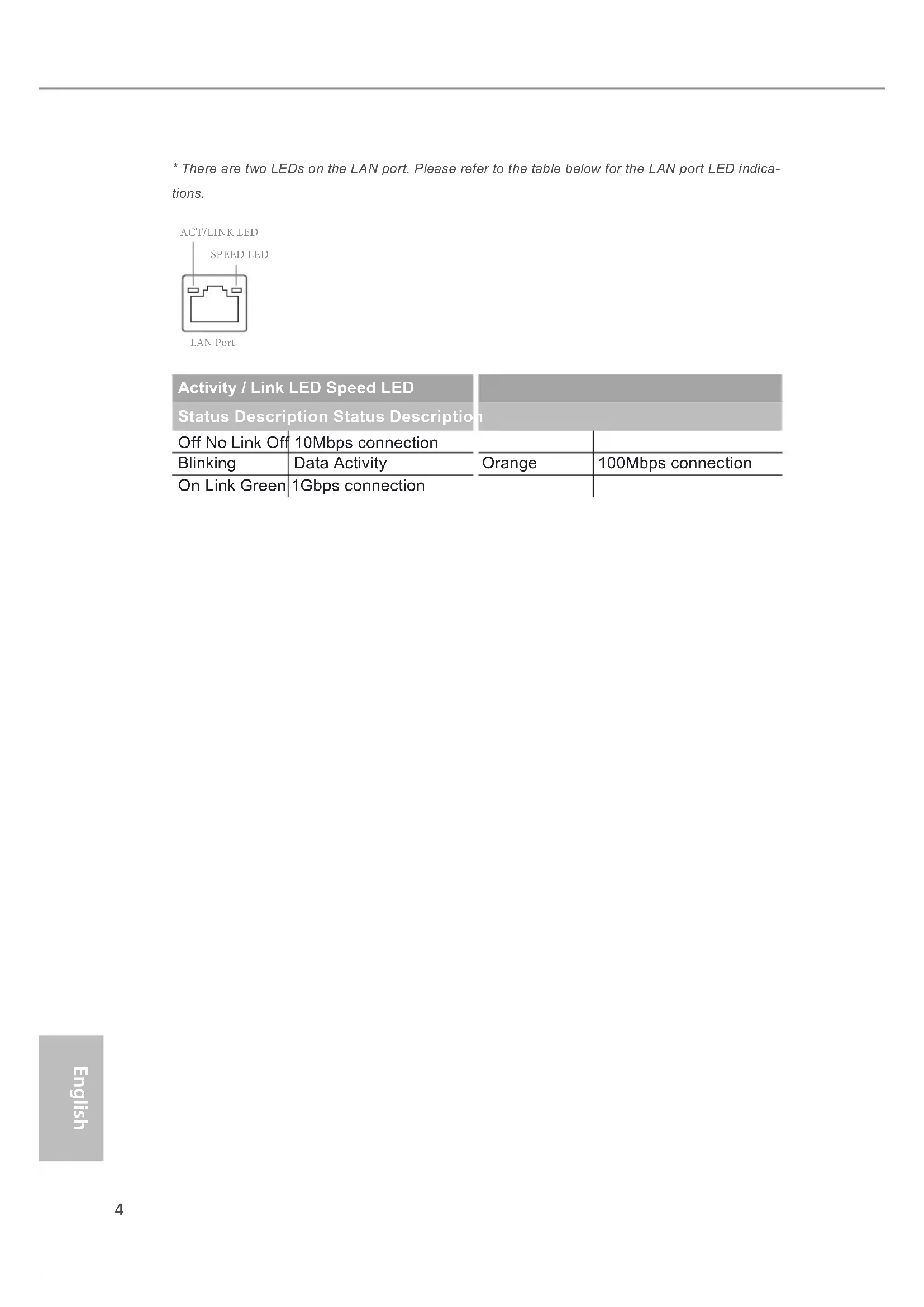
- There are two LEDs on the LAN port. Please refer to the table below for the LAN port LED indica- tions. Activity / Link LED Speed LED Status Description Status Description Off No Link Off 10Mbps connection Blinking Data Activity Orange 100Mbps connection On Link Green 1Gbps connection
Thank you for purchasing ASRock FM2A88X+ BTC motherboard, a reliable moth- erboard produced under ASRock’s consistently stringent quality control. It delivers excellent performance with robust design conforming to ASRock’s commitment to quality and endurance. In this documentation, Chapter 1 and 2 contains the introduction of the motherboard and step-by-step installation guides. Chapter 3 contains the operation guide of the software and utilities. Chapter 4 contains the conguration guide of the BIOS setup. Because the motherboard specications and the BIOS software might be updated, the content of this manual will be subject to change without notice. In case any modications of this manual occur, the updated ver- sion will be available on ASRock website without further notice. You may nd the latest VGA cards and CPU support lists on ASRock website as well. ASRock website http://www.asrock.com If you require technical support related to this motherboard, please visit our website for specic information about the model you are using. www.asrock.com/support/index.asp
- High Density Glass Fabric PCB CPU
- Supports Socket FM2+ 95W / FM2 100W processors
- 4 + 2 Power Phase design Chipset
- AMD A88X (Bolton-D4) Memory
- Dual Channel DDR3 Memory Technology
- Supports DDR3 2400+(OC)/2133(OC)/ 1866(OC)/1600/1333/1066 non-ECC, un-buffered memory (see CAUTION 1)
- Max. capacity of system memory: 64GB (see CAUTION
- SSupports AMD Memory Prole Technology (AMP) up to AMP 2400
- 15μ Gold Contact in DIMM Slots Expan- sion Slot
- 1 x PCI Express 3.0 x16 Slot (PCIE4 @ x16 mode)
- PCIE 3.0 is only supported with FM2+ CPU. With FM2 CPU, it only supports PCIE 2.0.
- Integrated AMD Radeon
R7/R5 Series Graphics in A-series APU
- DirectX 11.1, Pixel Shader 5.0 with FM2+ CPU. DirectX 11, Pixel Shader 5.0 with FM2 CPU.
- Max. shared memory 2GB
- Dual VGA output: support DVI-D and D-Sub by independent display controllers
- Supports Dual-link DVI-D with max. resolution up to 2560x1600 @ 60Hz6 7 English
- Supports D-Sub with max. resolution up to 1920x1200 @ 60Hz
- Supports AMD Steady Video
2.0: New video post processing capability for automatic jitter reduction on home/online video
- Supports HDCP with DVI-D Port
- Supports Full HD 1080p Blu-ray (BD) playback with DVI-D Port Audio
NE5532 Premium Headset Amplier (Supports up to 600 ohm headsets) (Line-Out on rear I/O only) LAN
- Supports Wake-On-WAN (see CAUTION 3)
- Supports Wake-On-LAN
- Supports Lightning/ESD Protection (ASRock Full Spike Protection)
- Supports LAN Cable Detection
- Supports Energy Efcient Ethernet 802.3az
- Supports PXE Rear Panel I/O
- 4 x USB 2.0 Ports (Supports ESD Protection (ASRock Full Spike Protection))
- 2 x USB 3.0 Ports (AMD A88X (Bolton-D4)) (Supports ESD Protection (ASRock Full Spike Protection))
- 1 x RJ-45 LAN Port with LED (ACT/LINK LED and SPEED LED)
- HD Audio Jacks: Line in / Front Speaker / Microphone8 9 English
- 8 x SATA3 6.0 Gb/s Connectors, support RAID (RAID 0, RAID 1, RAID 5 and RAID 10), NCQ, AHCI and Hot Plug Connec- tor
- 2 x CPU Fan Connectors (1 x 4-pin, 1 x 3-pin)
- 3 x Chassis Fan Connectors (1 x 4-pin, 2 x 3-pin)
- 1 x Power Fan Connector (3-pin)
- 1 x Front Panel Audio Connector
- 1 x USB 3.0 Header by AMD A88X (Bolton-D4) (Sup- ports 2 USB 3.0 ports) (Supports ESD Protection (AS- Rock Full Spike Protection)) BIOS Feature
- 64Mb AMI UEFI Legal BIOS with GUI support
- Supports “Plug and Play”
- ACPI 1.1 Compliant wake up events
- DRAM, CPU Voltage multi-adjustment Support
- Drivers, Utilities, AntiVirus Software (Trial Version), Google Chrome Browser and Toolbar, Start8 (30 days trial) Hardware Monitor
- CPU temperature sensing
- Chassis temperature sensing
- CPU/Chassis Quiet Fan
- CPU/Chassis Fan multi-speed control
- For the updated Windows® 10 driver, please visit ASRock’s website for details: http://www.asrock.com
- ErP/EuP ready (ErP/EuP ready power supply is required) WARNING Please realize that there is a certain risk involved with overclocking, including adjusting the setting in the BIOS, applying Untied Overclocking Technology, or using third-party overclocking tools. Overclocking may affect your system’s stability, or even cause damage to the components and devices of your system. It should be done at your own risk and expense. We are not responsible for possible damage caused by overclocking.
- For detailed product information, please visit our website: http://www.asrock.com CAUTION!
1. Whether 2400/2133/1866/1600MHz memory speed is support-
ed depends on the CPU you adopt. If you want to adopt DDR3 2400/2133/1866/1600 memory module on this motherboard, please refer to the memory support list on our website for the compatible memory modules. ASRock website http://www.asrock.com
2. Due to the operating system limitation, the actual memory size
may be less than 4GB for the reservation for system usage un- der Windows
64-bit OS with 64- bit CPU, there is no such limitation. You can use ASRock XFast RAM to utilize the memory that Windows
3. Wake-On-WAN allows you to wake up this system from remote
mobile devices, such as smart phones, tables, or other PCs. It needs third-party softwares and applications to utilize this feature. Please visit our website for Home Cloud topic.10 11 English
ASRock A-Tuning A-Tuning is ASRock’s multi purpose software suite with a new interface, more new features and improved utilities, including XFast RAM, Dehumidier, Good Night LED, FAN-Tastic Tun- ing, OC Tweaker and a whole lot more. ASRock Instant Boot ASRock Instant Boot allows you to turn on your PC in just a few seconds, provides a much more efcient way to save energy, time, money, and improves system running speed for your sys- tem. It leverages the S3 and S4 ACPI features which normally enable the Sleep/Standby and Hibernation modes in Windows
to shorten boot up time. By calling S3 and S4 at specic timing during the shutdown and startup process, Instant Boot allows you to enter your Windows
desktop in a few seconds. ASRock Instant Flash ASRock Instant Flash is a BIOS ash utility embedded in Flash ROM. This convenient BIOS update tool allows you to update system BIOS without entering operating systems rst like MS- DOS or Windows
. With this utility, you can press the <F6> key during the POST or the <F2> key to enter into the BIOS setup menu to access ASRock Instant Flash. Just launch this tool and save the new BIOS le to your USB ash drive, oppy disk or hard drive, then you can update your BIOS only in a few clicks without preparing an additional oppy diskette or other compli- cated ash utility. Please be noted that the USB ash drive or hard drive must use FAT32/16/12 le system. ASRock APP Charger If you desire a faster, less restricted way of charging your Apple devices, such as iPhone/iPad/iPod Touch, ASRock has prepared a wonderful solution for you - ASRock APP Charger. Simply install the APP Charger driver, it makes your iPhone charge much quickly from your computer and up to 40% faster than before. ASRock APP Charger allows you to quickly charge many Apple devices simultaneously and even supports continu- ous charging when your PC enters into Standby mode (S1),10 11 English
Suspend to RAM (S3), hibernation mode (S4) or power off (S5). With APP Charger driver installed, you can easily enjoy the mar- velous charging experience. ASRock XFast LAN ASRock XFast LAN provides a faster internet access, which includes the benefits listed below. LAN Application Prioritiza- tion: You can congure your application’s priority ideally and/or add new programs. Lower Latency in Game: After setting online game’s priority higher, it can lower the latency in games. Trafc Shaping: You can watch Youtube HD videos and download si- multaneously. Real-Time Analysis of Your Data: With the status window, you can easily recognize which data streams you are transferring currently. ASRock XFast RAM ASRock XFast RAM is included in A-Tuning. It fully utilizes the memory space that cannot be used under Windows
32-bit operating systems. ASRock XFast RAM shortens the loading time of previously visited websites, making web surng faster than ever. And it also boosts the speed of Adobe Photoshop 5 times faster. Another advantage of ASRock XFast RAM is that it reduces the frequency of accessing your SSDs or HDDs in order to extend their lifespan. ASRock Crashless BIOS ASRock Crashless BIOS allows users to update their BIOS without fear of failing. If power loss occurs during the BIOS up- date process, ASRock Crashless BIOS will automatically nish the BIOS update procedure after regaining power. Please note that BIOS les need to be placed in the root directory of your USB disk. Only USB2.0 ports support this feature. ASRock OMG (Online Management Guard) Administrators are able to establish an internet curfew or restrict internet access at specied times via OMG. You may schedule the starting and ending hours of internet access granted to other users. In order to prevent users from bypassing OMG, guest accounts without permission to modify the system time are re- quired.12 13 English
ASRock Internet Flash ASRock Internet Flash searches for available UEFI firmware updates from our servers. In other words, the system can auto- detect the latest UEFI from our servers and ash them without entering Windows
OS. ASRock UEFI System Browser ASRock UEFI system browser is a useful tool included in graphical UEFI. It can detect the devices and configurations that users are currently using in their PC. With the UEFI system browser, you can easily examine the current system congura- tion in UEFI setup. ASRock UEFI Tech Service Contact ASRock Tech Service by sending a support request from the UEFI setup utility if you are having trouble with your PC. ASRock Dehumidier Function Users may prevent motherboard damages due to dampness by enabling “Dehumidier Function”. When enabling Dehumidier Function, the computer will power on automatically to dehumidi- fy the system after entering S4/S5 state. ASRock Easy RAID Installer ASRock Easy RAID Installer can help you to copy the RAID driver from a support CD to your USB storage device. After copying the RAID driver to your USB storage device, please change “SATA Mode” to “RAID”, then you can start installing the OS in RAID mode. ASRock Easy Driver Installer For users that don’t have an optical disk drive to install the drivers from our support CD, Easy Driver Installer is a handy tool in the UEFI that installs the LAN driver to your system via an USB storage device, then downloads and installs the other required drivers automatically. ASRock Interactive UEFI ASRock Interactive UEFI is a blend of system configuration tools, cool sound effects and stunning visuals. The unprec- edented UEFI provides a more attractive interface and brings a lot more amusing.12 13 English
ASRock Fast Boot With ASRock’s exclusive Fast Boot technology, it takes less than 1.5 seconds to logon to Windows
8 from a cold boot. No more waiting! The speedy boot will completely change your user experience and behavior. ASRock X-Boost Brilliantly designed for combo overclocking, ASRock X-Boost Technology is able to unleash the hidden power of your CPUs. Simply press “X” when turning on the PC, X-Boost will automati- cally overclock the relative components to get up to 15.77% performance boost! With the smart X-Boost, overclocking CPU can become a near one-button process. ASRock Restart to UEFI Windows
8 brings the ultimate boot up experience. The light- ning boot up speed makes it hard to access the UEFI setup. AS- Rock Restart to UEFI technology is designed for those requiring frequent UEFI access. It is included in ASRock’s exclusive all- in-one A-Tuning tuning program that allows users to easily enter the UEFI automatically when turning on the PC next time. Just simply enable this function; the PC will be assured to access the UEFI directly in the very beginning. ASRock Good Night LED ASRock Good Night LED technology offers you a better sleep- ing environment by extinguishing the unessential LEDs. By enabling Good Night LED in the BIOS, the LAN/Power/HDD LEDs will be switched off when the system is powered on. Good Night LED will automatically switch off the Power and Keyboard LEDs when the system enters into Standby/Hiberna- tion mode as well. ASRock USB Key In a world where time is money, why waste precious time everyday typing usernames to log in to Windows? Why should we even bother memorizing those foot long passwords? Just plug in the USB Key and let your computer log in to windows automatically!14 15 English
ASRock FAN-Tastic Tuning ASRock FAN-Tastic Tuning is included in A-Tuning. Congure up to ve different fan speeds using the graph. The fans will automatically shift to the next speed level when the assigned temperature is met.14 15 English
This is an ATX form factor motherboard. Before you install the motherboard, study the conguration of your chassis to ensure that the motherboard ts into it. Pre-installation Precautions Take note of the following precautions before you install motherboard components or change any motherboard settings. Before you install or remove any component, ensure that the power is switched off or the power cord is detached from the power supply. Failure to do so may cause severe damage to the motherboard, peripherals, and/or components.
1. Unplug the power cord from the wall socket before touching any
2. To avoid damaging the motherboard components due to static elec-
tricity, NEVER place your motherboard directly on the carpet or the like. Also remember to use a grounded wrist strap or touch a safety grounded object before you handle components.
3. Hold components by the edges and do not touch the ICs.
4. Whenever you uninstall any component, place it on a grounded anti-
static pad or in the bag that comes with the component.
5. When placing screws into the screw holes to secure the mother-
board to the chassis, please do not over-tighten the screws! Doing so may damage the motherboard.16 17 English
2.1 CPU Installation
Step 1. Unlock the socket by lifting the lever up to a 90
angle. Step 2. Position the CPU directly above the socket such that the CPU corner with the golden triangle matches the socket corner with a small triangle. Step 3. Carefully insert the CPU into the socket until it ts in place. The CPU ts only in one correct orientation. DO NOT force the CPU into the socket to avoid bending of the pins. Step 4. When the CPU is in place, press it rmly on the socket while you push down the socket lever to secure the CPU. The lever clicks on the side tab to indicate that it is locked.16 17 English
2.2 Installation of CPU Fan and Heatsink
After you install the CPU into this motherboard, it is necessary to install a larger heatsink and cooling fan to dissipate heat. You also need to spray thermal grease between the CPU and the heatsink to improve heat dis- sipation. Make sure that the CPU and the heatsink are securely fastened and in good contact with each other. Then connect the CPU fan to the CPU FAN connector (CPU_FAN1 and CPU_FAN2, see Page 1, No. 2 and No. 3). For proper installation, please kindly refer to the instruction manuals of the CPU fan and the heatsink.18 19 English
This motherboard provides four 240-pin DDR3 (Double Data Rate 3) DIMM slots, and supports Dual Channel Memory Technology. Dual Channel Memory Conguration The DIMM only ts in one correct orientation. It will cause permanent dam- age to the motherboard and the DIMM if you force the DIMM into the slot at incorrect orientation. Priority DDR3_A1 DDR3_A2 DDR3_B1 DDR3_B2 1 Populated Populated 2 Populated Populated 3 Populated Populated Populated Populated
For dual channel conguration, you always need to install identical (the same brand, speed, size and chip-type) DDR3 DIMM pairs.
It is unable to activate Dual Channel Memory Technology with only one or three memory module installed.
It is not allowed to install a DDR or DDR2 memory module into a DDR3 slot; otherwise, this motherboard and DIMM may be damaged.
If you adopt DDR3 2400/2133/1866/1600 memory modules on this moth- erboard, it is recommended to install them on DDR3_A2 and DDR3_B2 slots.18 19 English
2.4 Expansion Slots (PCI and PCI Express Slots)
There are 2 PCI slots and 5 PCI Express slots on this motherboard. PCI Slots: PCI slots are used to install expansion cards that have the 32-bit PCI interface. PCIE Slots: PCIE1 / PCIE2 / PCIE3 (PCIe 2.0 x1 slot) is used for PCI Express cards with x1 lane width cards PCIE4 (PCIe 3.0 x16 slot) is used for PCI Express x16 lane width graphics cards PCIE5 (PCIe 2.0 x16 slot) is used for PCI Express x4 lane width cards PCIe Slot Congurations For a better thermal environment, please connect a chassis fan to the moth- erboard’s chassis fan connector (CHA_FAN1, CHA_FAN2, or CHA_FAN3) when using multiple graphics cards. Before installing an expansion card, please make sure that the power supply is switched off or the power cord is unplugged. Please read the documenta- tion of the expansion card and make necessary hardware settings for the card before you start the installation. PCIE4 PCIE5 Single Graphics Card x16 N/A Two Graphics Cards in CrossFireX
Mode x16 x420 21 English
The illustration shows how jumpers are setup. When the jumper cap is placed on pins, the jumper is “Short”. If no jumper cap is placed on pins, the jumper is “Open”. The illustration shows a 3-pin jumper whose pin1 and pin2 are “Short” when jumper cap is placed on these 2 pins. Jumper Setting Description Clear CMOS Jumper (CLRCMOS1) (see p.1, No. 14) Note: CLRCMOS1 allows you to clear the data in CMOS. To clear and reset the system parameters to default setup, please turn off the computer and unplug the power cord from the power supply. After waiting for 15 seconds, use a jumper cap to short pin2 and pin3 on CLRCMOS1 for 5 seconds. However, please do not clear the CMOS right after you update the BIOS. If you need to clear the CMOS when you just nish updating the BIOS, you must boot up the system rst, and then shut it down before you do the clear-CMOS ac- tion. Please be noted that the password, date, time, user default prole, 1394 GUID and MAC address will be cleared only if the CMOS battery is removed. Clear CMOSDefault USB Power Jumper (3-pin USB01_PWR1) (see p.1, No. 25) +5V (Default) +5VSB Note: USB Power Jumper is specically designed for users who use LED key- board / mouse. (only for the USB01 ports) Pin 1-2 shorted (default): Stable voltage and high current is provided for LED keyboard / mouse. The backlight of your keyboard / mouse will be OFF when the PC is off. Pin 2-3 shorted: +5VSB voltage is provided for LED keyboard / mouse. Enable the wake-up function of your keyboard / mouse. The backlight of your keyboard / mouse will be ON when the PC is in standby mode.22 23 English
2.6 Onboard Headers and Connectors
Onboard headers and connectors are NOT jumpers. Do NOT place jumper caps over these headers and connectors. Placing jumper caps over the headers and connectors will cause permanent damage of the motherboard! USB 2.0 Headers Besides four default USB 2.0 (9-pin USB6_7) ports on the I/O panel, there (see p.1 No. 19) are two USB 2.0 headers on (9-pin USB8_9) this motherboard. Each USB 2.0 (see p.1 No. 18) header can support two USB
6.0 Gb/s data transfer rate.
USB 3.0 Header Besides two default USB 3.0 (19-pin USB3_2_3) ports on the I/O panel, there is (see p.1 No. 7) one USB 3.0 header on this motherboard. This USB 3.0 header can support two USB 3.0 ports.
Front Panel Audio Header This is an interface for the front (9-pin HD_AUDIO1) panel audio cable that allows (see p.1 No. 21) convenient connection and control of audio devices.
MIC_RETPRESENCE#GNDOUT2_RMIC2_RMIC2_LOUT_RET System Panel Header This header accommodates (9-pin PANEL1) several system front panel (see p.1 No. 13) functions.
1. High Denition Audio supports Jack Sensing, but the panel wire on
the chassis must support HDA to function correctly. Please follow the instruction in our manual and chassis manual to install your system.
2. If you use AC’97 audio panel, please install it to the front panel audio
header as below: A. Connect Mic_IN (MIC) to MIC2_L. B. Connect Audio_R (RIN) to OUT2_R and Audio_L (LIN) to OUT2_L. C. Connect Ground (GND) to Ground (GND). D. MIC_RET and OUT_RET are for HD audio panel only. You don’t need to connect them for AC’97 audio panel. E. To activate the front mic. For Windows
bit OS: Go to the “FrontMic” Tab in the Realtek Control panel. Adjust “Recording Volume”. Connect the power switch, reset switch and system status indicator on the chassis to this header according to the pin assignments below. Note the positive and negative pins before connecting the cables. PWRBTN (Power Switch): Connect to the power switch on the chassis front panel. You may con- gure the way to turn off your system using the power switch. RESET (Reset Switch): Connect to the reset switch on the chassis front panel. Press the reset switch to restart the computer if the computer freezes and fails to per- form a normal restart.24 25 English
Power LED Header Please connect the chassis (3-pin PLED1) power LED to this header to (see p.1 No. 16) indicate system power status. The LED is on when the system is operating. The LED keeps blinking in S1 state. The LED is off in S3/S4 state or S5 state (power off). Chassis Speaker Header Please connect the chassis (4-pin SPEAKER 1) speaker to this header. (see p.1 No. 17)
+5VDUMMYDUMMYSPEAKER Chassis and Power Fan Please connect the fan cable Connectors to the fan connector and (4-pin CHA_FAN1) match the black wire to the (see p.1 No. 23) ground pin. (3-pin CHA_FAN2) (see p.1 No. 8) (3-pin CHA_FAN3) (see p.1 No. 15) GND +12V
PLED (System Power LED): Connect to the power status indicator on the chassis front panel. The LED is on when the system is operating. The LED keeps blinking when the sys-tem is in S1 sleep state. The LED is off when the system is in S3/S4 sleep state or powered off (S5). HDLED (Hard Drive Activity LED): Connect to the hard drive activity LED on the chassis front panel. The LED is on when the hard drive is reading or writing data. The front panel design may differ by chassis. A front panel module mainly consists of power switch, reset switch, power LED, hard drive activity LED, speaker and etc. When connecting your chassis front panel module to this header, make sure the wire assignments and the pin assign-ments are matched correctly.24 25 English
(3-pin PWR_FAN1) (see p.1 No. 22) Though this motherboard provides 4-Pin CPU fan (Quiet Fan) support, the 3-Pin CPU fan still can work successfully even without the fan speed control function. If you plan to connect the 3-Pin CPU fan to the CPU fan connector on this motherboard, please connect it to Pin 1-3. ATX Power Connector Please connect an ATX power (24-pin ATXPWR1) supply to this connector. (see p.1 No. 6)
Pin 1-3 Connected 3-Pin Fan Installation
Though this motherboard provides 24-pin ATX power connector, it can still work if you adopt a traditional 20-pin ATX power supply. To use the 20-pin ATX power supply, please plug your power supply along with Pin 1 and Pin 13. 20-Pin ATX Power Supply Installation
CPU Fan Connector Please connect the CPU fan (4-pin CPU_FAN1) cable to the connector and (see p.1 No. 2) match the black wire to the ground pin. (3-pin CPU_FAN2) (see p.1, No. 3) GND+ 12V CPU_ FAN_SPEED
FM2A88X+ BTCFM2A88X+ BTC Serial port Header This COM1 header supports a (9-pin COM1) serial port module. (see p.1 No. 20) CCTS#1RRTS#1DDSR#1DDTR#1RRXD1GNDTTXD1DDCD#1 RRI#1 ATX 12V Power Connector Please connect an ATX 12V (8-pin ATX12V1) power supply to this connector. (see p.1 No. 1) Though this motherboard provides 8-pin ATX 12V power connector, it can still work if you adopt a traditional 4-pin ATX 12V power supply. To use the 4-pin ATX power supply, please plug your power supply along with Pin 1 and Pin 5. 4-Pin ATX 12V Power Supply Installation PCIe Power Connector (4-pin PCIE_PWR1) (see p.1, No. 24) Please connect a 4 pin molex power cable to this connector when more than three graphics cards are installed.26 2726 27 Deutsch FM2A88X+ BTCFM2A88X+ BTC
- AMD A88X (Bolton-D4)
Extreme Memory Prole (XMP)1.3/1.2
- PCB High Density Glass Fabric CPU
- AMD A88X (Bolton-D4) Mémoire
- Supporta Wake-On-WAN
- Supporta Wake-On-LAN
- Supporta “Plug and Play”
- ACPI 1.1 compliance wake up events
- Soporta “jumper free setup”
- High Density Glass Fabric PCB
- AMD A88X (Bolton-D4)
Extreme Memory Prole (XMP)1.3/1.2
- PCIE x1 Gigabit LAN 10/100/1000 Mb/sn
- AMD A88X (Bolton-D4)
- AMD A88X (Bolton-D4)
- AMD A88X (Bolton-D4)
- Supports D-Sub with max. resolution up to 1920x1200 @ 60Hz
- Supports AMD Steady VideoTM 2.0: New video post processing capability for automatic jitter reduction on home/online video
- ACPI 1.1 Compliance Wake Up Events
- ErP/EuP Ready (memerlukan catu daya ErP/EuP ready)Contact Information If you need to contact ASRock or want to know more about ASRock, you’re welcome to visit ASRock’s website at http://www.asrock.com; or you may contact your dealer for further information. For technical questions, please submit a support request form at http://www.asrock.com/support/tsd.asp ASRock Incorporation 2F., No.37, Sec. 2, Jhongyang S. Rd., Beitou District, Taipei City 112, Taiwan (R.O.C.) ASRock EUROPE B.V. Bijsterhuizen 3151 6604 LV Wijchen e Netherlands Phone: +31-24-345-44-33 Fax: +31-24-345-44-38 ASRock America, Inc. 13848 Magnolia Ave, Chino, CA91710 U.S.A. Phone: +1-909-590-8308 Fax: +1-909-590-1026