C621A WS - Motherboard ASROCK - Free user manual and instructions
Find the device manual for free C621A WS ASROCK in PDF.
Download the instructions for your Motherboard in PDF format for free! Find your manual C621A WS - ASROCK and take your electronic device back in hand. On this page are published all the documents necessary for the use of your device. C621A WS by ASROCK.
USER MANUAL C621A WS ASROCK
Version 1.0 Published July 2021 Copyright©2021 ASRock INC. All rights reserved. Copyright Notice: No part of this documentation may be reproduced, transcribed, transmitted, or translated in any language, in any form or by any means, except duplication of documentation by the purchaser for backup purpose, without written consent of ASRock Inc. Products and corporate names appearing in this documentation may or may not be registered trademarks or copyrights of their respective companies, and are used only for identication or explanation and to the owners’ benet, without intent to infringe. Disclaimer: Specications and information contained in this documentation are furnished for informational use only and subject to change without notice, and should not be constructed as a commitment by ASRock. ASRock assumes no responsibility for any errors or omissions that may appear in this documentation. With respect to the contents of this documentation, ASRock does not provide warranty of any kind, either expressed or implied, including but not limited to the implied warranties or conditions of merchantability or tness for a particular purpose. In no event shall ASRock, its directors, ocers, employees, or agents be liable for any indirect, special, incidental, or consequential damages (including damages for loss of prots, loss of business, loss of data, interruption of business and the like), even if ASRock has been advised of the possibility of such damages arising from any defect or error in the documentation or product. is device complies with Part 15 of the FCC Rules. Operation is subject to the following two conditions: (1) this device may not cause harmful interference, and (2) this device must accept any interference received, including interference that may cause undesired operation.
CALIFORNIA, USA ONLY
e Lithium battery adopted on this motherboard contains Perchlorate, a toxic substance controlled in Perchlorate Best Management Practices (BMP) regulations passed by the California Legislature. When you discard the Lithium battery in California, USA, please follow the related regulations in advance. “Perchlorate Material-special handling may apply, see www.dtsc.ca.gov/hazardouswaste/ perchlorate” ASRock Website: http://www.asrock.comAUSTRALIA ONLY Our goods come with guarantees that cannot be excluded under the Australian Consumer Law. You are entitled to a replacement or refund for a major failure and compensation for any other reasonably foreseeable loss or damage caused by our goods. You are also entitled to have the goods repaired or replaced if the goods fail to be of acceptable quality and the failure does not amount to a major failure. If you require assistance please call ASRock Tel : +886-2-28965588 ext.123 (Standard International call charges apply)C621A WS PB 1 English Motherboard Layout
English No. Item Status Description 1 SB_PWR1 Green STB PWR ready 2 FAN_LED1 Amber FAN1 failed 3 FAN_LED2 Amber FAN2 failed 4 FAN_LED3 Amber FAN3 failed 5 FAN_LED4 Amber FAN4 failed 6 FAN_LED5 Amber FAN5 failed 7 BLED1 Green BMC heartbeat LED6 7 English I/O Panel
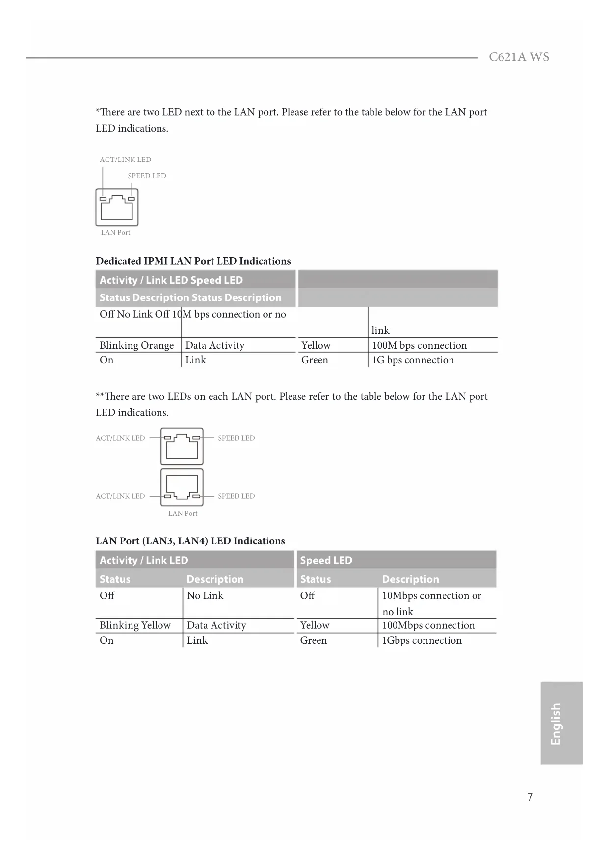
English *ere are two LED next to the LAN port. Please refer to the table below for the LAN port LED indications. Dedicated IPMI LAN Port LED Indications Activity / Link LED Speed LED Status Description Status Description O No Link O 10M bps connection or no link Blinking Orange Data Activity Yellow 100M bps connection On Link Green 1G bps connection **ere are two LEDs on each LAN port. Please refer to the table below for the LAN port LED indications. LAN Port (LAN3, LAN4) LED Indications Activity / Link LED Speed LED Status Description Status Description O No Link O 10Mbps connection or no link Blinking Yellow Data Activity Yellow 100Mbps connection On Link Green 1Gbps connection
SPEED LED8 9 English ***ere are two LEDs on each LAN port. Please refer to the table below for the LAN port LED indications. LAN Port (LAN1, LAN2) LED Indications Activity / Link LED Speed LED Status Description Status Description O No Link O 100Mbps connection or no link Blinking Green Data Activity Yellow 1Gbps connection On Link Green 10Gbps connection
ank you for purchasing ASRock C621A WS motherboard, a reliable motherboard produced under ASRock’s consistently stringent quality control. It delivers excellent performance with robust design conforming to ASRock’s commitment to quality and endurance.
1 x CPU Non-Fabric Carrier (Optional)
1 x I/O Panel Shield If any items are missing or appear damaged, contact your authorized dealer.Because the motherboard specications and the BIOS soware might be updated, the content of this documentation will be subject to change without notice. In case any modications of this documentation occur, the updated version will be available on ASRock’s website without further notice. If you require technical support related to this motherboard, please visit our website for specic information about the model you are using. You may nd the latest VGA cards and CPU support list on ASRock’s website as well. ASRock website http://www.asrock.com.10 11 English
Supports 3rd Generation Intel® Xeon® Scalable Processors
Eight Channel Memory Technology (1DPC)
Supports DDR4 3200/2933/2666/2400/2133/1866 DDR4
Max. capacity of system memory: RDIMM: 64GB, LRDIMM:
- If PCIE2 is occupied, PCIE3 will downgrade to x8 mode. If PCIE4 is occupied, PCIE5 will downgrade to x8 mode. If PCIE6 is occupied, PCIE7 will downgrade to x8 mode. Graphics
Supports D-Sub with max. resolution up to 1920x1200 @ 60Hz LAN 2 x 10 Gigabit LAN 100/1000/2500/5000/10000 Mb/s (Intel® X710-AT2)
Supports Wake-On-LAN
Supports Lightning/ESD Protection
Supports Energy Ecient Ethernet 802.3az
Supports PXEC621A WS
Supports Wake-On-LAN
Supports Lightning/ESD Protection
Supports Energy Ecient Ethernet 802.3az
Supports iKVM and vMedia Storage
- Supports Intel® Optane
- Supports NVMe SSD as boot disks
- Supports ASRock U.2 Ki RAID
Supports RAID 0, RAID 1, RAID 5 and RAID 10 for SATA storage devices
Supports RAID 0, RAID 1, RAID 5 for M.2 NVMe storage devices Rear Panel I/O
1 x UID Switch w/ LED
4 x USB 3.2 Gen1 Ports (Supports ESD Protection)
1 x RJ45 Dedicated IPMI LAN port Connector
1 x 24 pin ATX Power Connector (Hi-Density Power Connector)12 13 English
1 x 8 pin 12V Power Connector (Hi-Density Power Connector)
1 x 4 pin 12V Power Connector (Hi-Density Power Connector)
1 x USB 2.0 Header (Supports 2 USB 2.0 ports) (Supports ESD Protection)
1 x USB 3.2 Gen1 Headers (Support 2 USB 3.2 Gen1 ports) (Supports ESD Protection)
2 x Front Panel Type C USB 3.2 Gen2 Headers (Supports ESD Protection)
1 x Auxiliary Panel Header
1 x CPU HP-SMBus Connector
1 x Dr. Debug with LED BIOS Feature
ACPI 5.0 Compliant wake up events
Fan Tachometer: CPU, Rear, Front Fan Tachometer
Quiet Fan (Auto adjust chassis fan speed by CPU temperature): CPU Fan
Fan Multi-Speed Control: CPU, Rear, Front Fan
Win hyper-V Server 2012 R2
- Please refer to our website for the latest OS support list.
- On Ubuntu 16.04 (64bit) system, Intel Raid mode only supports UEFI BOOT.
- Ubuntu 18.04 (64bit) does not support Intel Raid mode (AHCI only). Certica- tions
ErP/EuP ready (ErP/EuP ready power supply is required) Please realize that there is a certain risk involved with overclocking, including adjusting the setting in the BIOS, applying Untied Overclocking Technology, or using third-party overclocking tools. Overclocking may aect your system’s stability, or even cause damage to the components and devices of your system. It should be done at your own risk and expense. We are not responsible for possible damage caused by overclocking.
- For detailed product information, please visit our website: http://www.asrock.com14 15 English
Chapter 2 Installation
is is an ATX form factor (12” x 9.6”, 30.5 cm x 24.4 cm) motherboard. Before you install the motherboard, study the conguration of your chassis to ensure that the motherboard ts into it.
Place screws into the holes indicated by circles to secure the motherboard to the chassis.
2.2 Pre-installation Precautions
Take note of the following precautions before you install motherboard components or change any motherboard settings.
1. Unplug the power cord from the wall socket before touching any components.
2. To avoid damaging the motherboard’s components due to static electricity, NEVER
place your motherboard directly on the carpet or the like. Also remember to use a grounded wrist strap or touch a safety grounded object before you handle the compo- nents.
3. Hold components by the edges and do not touch the ICs.
4. Whenever you uninstall any component, place it on a grounded anti-static pad or in
the bag that comes with the component.
5. When placing screws into the screw holes to secure the motherboard to the chassis,
please do not over-tighten the screws! Doing so may damage the motherboard. Make sure to unplug the power cord before installing or removing the motherboard. Failure to do so may cause physical injuries to you and damages to motherboard components.Do not over-tighten the screws! Doing so may damage the motherboard.Before you install or remove any component, ensure that the power is switched o or the power cord is detached from the power supply. Failure to do so may cause severe damage to the motherboard, peripherals, and/or components.C621A WS
2.3 Installing the CPU and Heatsink
1. Before you insert the CPU into the socket, please check if the PnP cap is on the socket,
if the CPU surface is unclean, or if there are any bent pins in the socket. Do not force to insert the CPU into the socket if above situation is found. Otherwise, the CPU will be seriously damaged.
1. Before you installed the heatsink, you need to spray thermal interface material between the CPU
and the heatsink to improve heat dissipation.
2. Illustration in this documentation are examples only. Heatsink or fan cooler type may dier.C621A WS
Socket CPU Carrier Heatsink20 21 English
is motherboard provides eight 288-pin DDR4 (Double Data Rate 4) DIMM slots in two groups, and supports Eight Channel Memory Technology. CPU1 A1 B1 C1 D1 E1 F1 G1 H1 1 DIMM
8 DIMMS # # # # # # # # 1. It is not allowed to install a DDR, DDR2 or DDR3 memory module into a DDR4 slot; otherwise, this motherboard and DIMM may be damaged.2. For eight channel conguration, you always need to install identical (the same brand, speed, size and chip-type) DDR4 DIMM pairs.22 23 English
ere are 7 PCIe slots on this motherboard. PCIE slot: PCIE1, PCIE3, PCIE5 and PCIE7 (PCIE 4.0 x16 slot, from CPU1) are used for PCIe x16 lane width cards. PCIE2, PCIE4 and PCIE6 (PCIE 4.0 x8 slot, from CPU1) are used for PCIe x8 lane width cards. Slot Generation Mechanical Electrical Source PCIE7 4.0 x16 x16 CPU1 PCIE6 4.0 x8 x8 CPU1 PCIE5 4.0 x16 x16 CPU1 PCIE4 4.0 x8 x8 CPU1 PCIE3 4.0 x16 x16 CPU1 PCIE2 4.0 x8 x8 CPU1 PCIE1 4.0 x16 x16 CPU1 PCIe Slot Congurations PCIE2 PCIE3 Single PCIE Card N/A x16 Two PCIE Cards x8 x8 PCIE4 PCIE5 Single PCIE Card N/A x16 Two PCIE Cards x8 x8 PCIE6 PCIE7 Single PCIE Card N/A x16 Two PCIE Cards x8 x824 25 English Installing an expansion card Step 1. Before installing an expansion card, please make sure that the power supply is switched o or the power cord is unplugged. Please read the documentation of the expansion card and make necessary hardware settings for the card before you start the installation. Step 2. Remove the system unit cover (if your motherboard is already installed in a chassis). Step 3. Remove the bracket facing the slot that you intend to use. Keep the screws for later use. Step 4. Align the card connector with the slot and press rmly until the card is completely seated on the slot. Step 5. Fasten the card to the chassis with screws. Step 6. Replace the system cover.C621A WS
e illustration shows how jumpers are setup. When the jumper cap is placed on the pins, the jumper is “Short”. If no jumper cap is placed on the pins, the jumper is “Open”. e illustration shows a 3-pin jumper whose pin1 and pin2 are “Short” when a jumper cap is placed on these 2 pins. MiniSAS HD SATA/PCIE Selection Jumper (3-pin MINISAS_1) (see p.1, No. 40) SATA (Default) PCIE CPU PECI Mode Jumper (3-pin PECI1) (see p.1, No. 48) CPU PECI connected to PCH CPU PECI connected to BMC (Default) Security Override Jumper (3-pin SEC_OR1) (see p.1, No. 33) Descriptor Security Override Not override (Default) ME Recovery Jumper (3-pin ME_RECOVERY1) (see p.1, No. 49) Normal Mode (Default) ME Recovery Mode Password Reset Jumper (3-pin PASSWORD_ CLEAR) (see p.1, No. 51) Normal Mode (Default) Password Clear26 27 English BIOS Recovery Jumper (3-pin BIOS_RECOVERY1) (see p.1, No. 45) Normal Mode (Default) Recover BIOS ESPI/LPC Selection Jumper (3-pin ESPI_LPC_SEL1) (see p.1, No. 54) ESPI (Default) LPC ESPI Flash Sharing Jumper (3-pin ESPI_SHARE) (see p.1, No. 42) Master ESPI Flash Sharing (Default) Slave ESPI Flash Sharing e illustration shows how jumpers are setup. When the jumper cap is placed on the pins, the jumper is “Short”. If no jumper cap is placed on the pins, the jumper is “Open”. BIOS Swap Override Jumper (ESPI_MODE1) (see p.1, No. 52) Open: Disable Override (Default) Short: Enable Override 2-pin JumperC621A WS
2.7 Onboard Headers and Connectors
System Panel Header (9-pin PANEL1) (see p.1, No. 29)
GNDRESET#PWRBTN#PLED-PLED+GNDHDLED-HDLED+
GND Connect the power switch, reset switch and system status indicator on the chassis to this header according to the pin assignments. Particularly note the positive and negative pins before connecting the cables. PWRBTN (Power Switch): Connect to the power switch on the chassis front panel. You may congure the way to turn o your system using the power switch. RESET (Reset Switch): Connect to the reset switch on the chassis front panel. Press the reset switch to restart the computer if the computer freezes and fails to perform a normal restart. PLED (System Power LED): Connect to the power status indicator on the chassis front panel. e LED is on when the system is operating. e LED is o when the system is in S4 sleep state or powered o (S5). HDLED (Hard Drive Activity LED): Connect to the hard drive activity LED on the chassis front panel. e LED is on when the hard drive is reading or writing data. e front panel design may dier by chassis. A front panel module mainly consists of power switch, reset switch, power LED, hard drive activity LED, speaker and etc. When connect- ing your chassis front panel module to this header, make sure the wire assignments and the pin assignments are matched correctly. Onboard headers and connectors are NOT jumpers. Do NOT place jumper caps over these headers and connectors. Placing jumper caps over the headers and connectors will cause permanent damage to the motherboard.28 29 English Auxiliary Panel Header (18-pin AUX_PANEL1) (see p.1, No. 30) GND SMB_CLK SMB_Alert CASEOPEN
is header supports multiple functions on the front panel, including the front panel SMB, internet status indicator and chassis intrusion pin. Mini-SAS HD Connector Right-Angle: (SATA_0_3) (see p.1, No. 22) SATA_0_3 is connector supports MiniSAS-to-SATA data cables for internal storage devices with up to 6.0 Gb/s data transfer rate. A. Front panel SMBus connecting pin (6-1 pin FPSMB) is header allows you to connect SMBus (System Management Bus) equipment. It can be used for communication between peripheral equipment in the system, which has slower transmission rates, and power management equipment. B. Internet status indicator (2-pin LAN1_LED, LAN2_LED) ese two 2-pin headers allow you to use the Gigabit internet indicator cable to connect to the LAN status indicator. When this indicator ickers, it means that the internet is prop- erly connected. C. Chassis intrusion pin (2-pin CHASSIS) is header is provided for host computer chassis with chassis intrusion detection designs. In addition, it must also work with external detection equipment, such as a chassis intru- sion detection sensor or a microswitch. When this function is activated, if any chassis component movement occurs, the sensor will immediately detect it and send a signal to this header, and the system will then record this chassis intrusion event. e default setting is set to the CASEOPEN and GND pin; this function is o. D. Locator LED (4-pin LOCATOR) is header is for the locator switch and LED on the front panel. E. System Fault LED (2-pin LOCATOR) is header is for the Fault LED on the system.C621A WS
English USB 3.2 Gen1 Header (19-pin USB3_5_6) (see p.1, No. 6) Besides four default USB 3.2 Gen1 ports on the I/O panel, there is one USB 3.2 Gen1 header on this motherboard. is USB 3.2 Gen1 header can support two USB 3.2 Gen1 ports. System Fan Connectors (6-pin FAN1) (6-pin FAN2) (6-pin FAN3) (6-pin FAN4) (6-pin FAN5) (see p.1, No. 3, 8, 13, 14, 19)
Please connect fan cables to the fan connectors and match the black wire to the ground pin. All fans support Fan Control. Front Panel Type C USB
(20-pin USB31_TC_1) see p.1, No. 23) (20-pin USB31_TC_2) (see p.1, No. 24) ere are two Front Panel Type C USB 3.2 Gen2 Header on this motherboard. ese headers are used for connecting USB 3.2 Gen2 modules for additional USB 3.2 Gen2 ports. *2 Type-C USB headers (USB31_TC1/ USB31_TC2) are shared with 2 SATA 7-pin headers (SSATA_2/SSATA_3) (BOM option). USB 2.0 Connector (USB_1) (see p.1, No. 34) ere is one vertical USB 2.0 port on this motherboard.
is is one header on this motherboard. is USB 2.0 header can support two ports. ATX Power Connector (24-pin ATXPWR1) (see p.1, No. 4)
GND N/A is motherboard provides a 24-pin ATX power connector. To use a 20-pin ATX power supply, please plug it along Pin 1 and Pin 13. ATX 12V Power Connectors (8-pin ATX12V1) (see p.1, No. 5) (4-pin ATX12V2) (see p.1, No. 7)
GND 12V is motherboard provides one 8-pin and one 4-pin ATX 12V power connectors. SATA DOM Power Connector (3-pin SATAPWR1) (see p.1, No. 15) (3-pin SATAPWR2) (see p.1, No. 12) GND +5V +12V Please use a SATA power cable to connect this SATA Power Connector and your SATA HDD for supplying power from the motherboard, when using DC-IN mode without SATA power supply. TPM Header (17-pin TPM1) (see p.1, No. 36)
is connector supports Trusted Platform Module (TPM) system, which can securely store keys, digital certicates, passwords, and data. A TPM system also helps enhance network security, protects digital identities, and ensures platform integrity.C621A WS
is connector supports Trusted Platform Module (TPM) system for SPI interface, which can securely store keys, digital certicates, passwords, and data. A TPM system also helps enhance network security, protects digital identities, and ensures platform integrity. PSU SMBus Header (5-pin PSU_SMB1) (see p.1, No. 2) +3V GND ALERT SMBCLKSMBDATA PSU SMBus monitors the status of the power supply, fan and system temperature. Intelligent Platform Management Bus Header (4-pin IPMB1) (see p.1, No. 43) IPMB_SDA IPMB_SCL No Connect GND This 4-pin connector is used to provide a cabled base-board or front panel connection for value added features and 3rd- party add-in cards, such as Emergency Management cards, that provide management features using the IPMB. Baseboard Management Controller SMBus Header (5-pin BMC_SMB_1) (see p.1, No. 41)
is header is used for the hot plug feature of HDDs on the backplane.32 33 English Serial ATA3 DOM Connectors (SATA_4) (see p.1, No. 18) (SATA_5) (see p.1, No. 16) e SATA3 DOM connectors support both SATA DOMs (Disk-On-Module) and SATA data cables for internal storage devices. Serial ATA3 Connectors Vertical: (SATA_4) (see p.1, No. 18) (SATA_5) (see p.1, No. 16) ese two SATA3 connectors support SATA data cables for internal storage devices with up to 6.0 Gb/s data transfer rate. *2 Type-C USB headers (USB31_TC1/ USB31_TC2) are shared with 2 SATA 7-pin headers (SSATA_2/SSATA_3) (BOM option). Serial Port Header (9-pin COM1) (see p.1, No. 44) CCTS#1RRTS#1DDSR#1DDTR#1RRXD1GNDTTXD1DDCD#1 RRI#1 is COM header supports a serial port module. Clear CMOS Pad (CLR MOS1) (see p.1, No. 58) is allows you to clear the data in CMOS. To clear CMOS, take out the CMOS battery and short the Clear CMOS Pad. Non Maskable Interrupt Button Header (NMI_BTN2) (see p.1, No. 46)
TR1 GND Please connect the thermal sensor cable to either pin 1-2 or pin 2-3 and the other end to the device which you wish to monitor its temperature. Front LAN LED Header (4-pin FRONT_LED_ LAN34) (see p.1, No. 35)
LAN3_LINK is 4-pin connector is used for the front LAN status indicator. Chassis Speaker Header (4-pin SPEAKER1) (see p.1, No. 26)
is header is used for PWM congurations. CPU VSENSE Header (3-pin CPU_VSENSE) (see p.1, No. 10)
is connector supports Intel® Virtual RAID on CPU and NVME/AHCI RAID on CPU PCIE. With the introduction of the Intel VROC product, there are three modes of operation: SKU HW key required Key features Pass-thru Not needed
- Pass-thru SKU features
- RAID 0, 1, 10 Premium ISS VROCPREMMOD VROCISSDMOD
- Standard SKU features
- RAID 5 Write Hole Closure *Only Intel SSDs are supported. *For further details on VROC, please refer to the ocial information released by Intel.C621A WS
With the UID button, You are able to locate the server you’re working on from behind a rack of servers. Unit Identication purpose LED/Switch (UID1) (see p.6, No. 9) When the UID button on the front or rear panel is pressed, the front/rear UID blue LED indicator will be truned on. Press the UID button again to turn o the indicator.
2.9 Driver Installation Guide
To install the drivers to your system, please insert the support CD to your optical drive rst. en, the drivers compatible to your system can be auto-detected and listed on the support CD driver page. Please follow the order from top to bottom to install those required drivers. erefore, the drivers you install can work properly.36 37 English
2.10 M.2_SSD (NGFF) Module Installation Guide
The M.2, also known as the Next Generation Form Factor (NGFF), is a small size and versatile card edge connector that aims to replace mPCIe and mSATA. e Ultra M.2 Socket (M2_1) supports a M.2 SATA3 6.0 Gb/s module or a M.2 PCI Express module up to Gen3 x4 (32Gb/s)
English ABC Step 3 Move the stando based on the module type and length. Skip Step 3 and 4 and go straight to Step
if you are going to use the default nut. Otherwise, release the stando by hand. ABC Step 4 Peel o the yellow protective lm on the nut to be used. Hand tighten the stando into the desired nut location on the motherboard. ABC ABC
Step 5 Align and gently insert the M.2 (NGFF) SSD module into the M.2 slot. Please be aware that the M.2 (NGFF) SSD module only ts in one orientation.
Win hyper-V Server 2012 R2
CCTS#1RRTS#1DDSR#1DDTR#1RRXD1GNDTTXD1
CentOS 6.8 (64 bits) / 7.4 (64 bits)
Win hyper-V Server 2012 R2
CCTS#1RRTS#1DDSR#1DDTR#1RRXD1GNDTTXD1
Supporto WOL (Wake-On-LAN)
Supporto Energy Ecient Ethernet 802.3az
Supporto WOL (Wake-On-LAN)
Supporto Energy Ecient Ethernet 802.3az
2 x Connettori SATA3 6,0 Gb/s
Win hyper-V Server 2012 R2
- Solo Pass-through (no RAID)
CentOS 6.8 (64 bits)/7.4 (64 bits)
Win hyper-V Server 2012 R2
CCTS#1RRTS#1DDSR#1DDTR#1RRXD1GNDTTXD1
2-pin Jumper109 C621A WS
2 x Conectores SATA3 6,0 Gb/s
1 x Conector HP-SMBus CPU
5 x dioda LED awarii wentylatora
Win hyper-V Server 2012 R2
CCTS#1RRTS#1DDSR#1DDTR#1RRXD1GNDTTXD1
Win hyper-V Server 2012 R2
Win hyper-V Server 2012 R2
PCIe Gen3x4 (32 Gb/s)
PCIe Gen3x1 (8 Gb/s)
Win hyper-V Server 2012 R2
2-pin Jumper189 C621A WS
Trusted Platform Module
Trusted Platform Module
Win hyper-V Server 2012 R2
- RAID 5 Write Hole Closure
Server Win hyper-V 2012 R2
Responsible Party Name: ASRock Incorporation Address:13848 Magnolia Ave, Chino, CA91710+1-909-590-8308/+1-909-590-1026 Phone/FaxNo: hereby declares that the product
Product Name : Motherboard Model Number : Conforms to the following specications:
FCC Part 15, Subpart B, Unintentional Radiators
Supplementary Information: is device complies with part 15 of the FCC Rules. Operation is subject to the following two conditions: (1) is device may not cause harmful interference, and (2) this device must accept any interference received, including interference that may cause undesired operation. Representative Person’s Name: James Signature : Date : May 12, 2017
C621A WSEU Declaration of Conformity
For the following equipment:Motherboard(Product Name)C621A WS / ASRock(Model Designation / Trade Name)ASRock Incorporation(Manufacturer Name)2F., No.37, Sec. 2, Jhongyang S. Rd., Beitou District, Taipei City 112, Taiwan (R.O.C.)(Manufacturer Address)ASRock EUROPE B.V.(Company Name)Bijsterhuizen 1111 6546 AR Nijmegen e Netherlands(Company Address)Person responsible for making this declaration:(Name, Surname)A.V.P(Position / Title)August 22, 2021(Date)P/N: 15G062313000AK V1.0 EMC
LVD —Directive 2014/35/EU (from April 20th, 2016) EN 60950-1 : 2011+ A2: 2013 ☐
(EU conformity marking)