X58 Deluxe3 - Motherboard ASROCK - Free user manual and instructions
Find the device manual for free X58 Deluxe3 ASROCK in PDF.
Download the instructions for your Motherboard in PDF format for free! Find your manual X58 Deluxe3 - ASROCK and take your electronic device back in hand. On this page are published all the documents necessary for the use of your device. X58 Deluxe3 by ASROCK.
USER MANUAL X58 Deluxe3 ASROCK
ASRock X58 Deluxe3 Motherboard EnglishEnglish EnglishEnglish English Copyright Notice:Copyright Notice: Copyright Notice:Copyright Notice: Copyright Notice: No part of this installation guide may be reproduced, transcribed, transmitted, or trans- lated in any language, in any form or by any means, except duplication of documen- tation by the purchaser for backup purpose, without written consent of ASRock Inc. Products and corporate names appearing in this guide may or may not be registered trademarks or copyrights of their respective companies, and are used only for identifica- tion or explanation and to the owners’ benefit, without intent to infringe. Disclaimer:Disclaimer: Disclaimer:Disclaimer: Disclaimer: Specifications and information contained in this guide are furnished for informational use only and subject to change without notice, and should not be constructed as a commitment by ASRock. ASRock assumes no responsibility for any errors or omissions that may appear in this guide. With respect to the contents of this guide, ASRock does not provide warranty of any kind, either expressed or implied, including but not limited to the implied warranties or conditions of merchantability or fitness for a particular purpose. In no event shall ASRock, its directors, officers, employees, or agents be liable for any indirect, special, incidental, or consequential damages (including damages for loss of profits, loss of business, loss of data, interruption of business and the like), even if ASRock has been advised of the possibility of such damages arising from any defect or error in the guide or product. This device complies with Part 15 of the FCC Rules. Operation is subject to the following two conditions: (1) this device may not cause harmful interference, and (2) this device must accept any interference received, including interference that may cause undesired operation.
CALIFORNIA, USA ONLY
The Lithium battery adopted on this motherboard contains Perchlorate, a toxic substance controlled in Perchlorate Best Management Practices (BMP) regulations passed by the California Legislature. When you discard the Lithium battery in California, USA, please follow the related regulations in advance. “Perchlorate Material-special handling may apply, see www.dtsc.ca.gov/hazardouswaste/perchlorate” ASRock Website: http://www.asrock.com Published December 2009 Copyright©2009 ASRock INC. All rights reserved.22
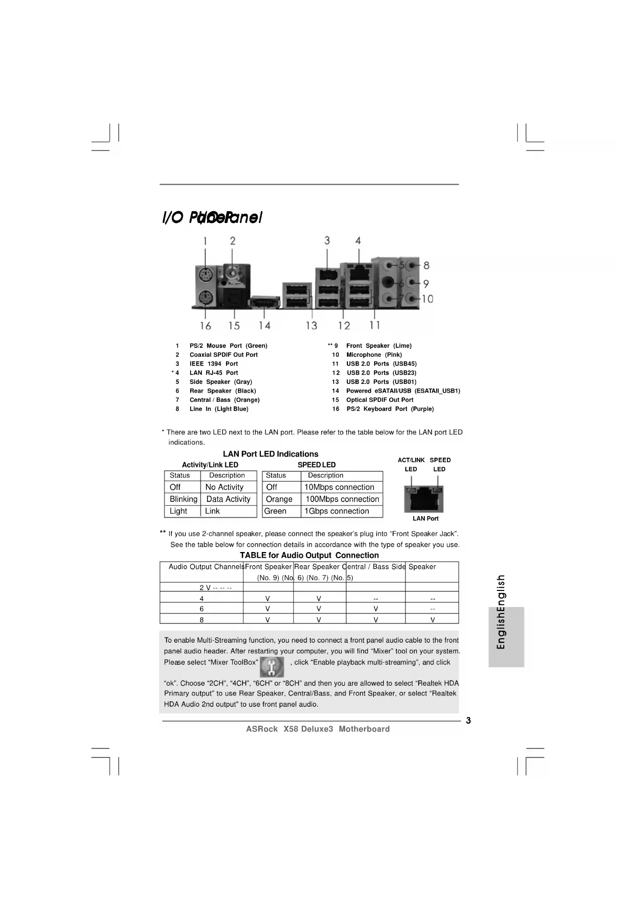
ASRock X58 Deluxe3 Motherboard EnglishEnglish EnglishEnglish English I/O PI/O P I/O PI/O P I/O P anelanel anelanel anel To enable Multi-Streaming function, you need to connect a front panel audio cable to the front panel audio header. After restarting your computer, you will find “Mixer” tool on your system. Please select “Mixer ToolBox” , click “Enable playback multi-streaming”, and click “ok”. Choose “2CH”, “4CH”, “6CH” or “8CH” and then you are allowed to select “Realtek HDA Primary output” to use Rear Speaker, Central/Bass, and Front Speaker, or select “Realtek HDA Audio 2nd output” to use front panel audio. ** If you use 2-channel speaker, please connect the speaker’s plug into “Front Speaker Jack”. See the table below for connection details in accordance with the type of speaker you use. TABLE for Audio Output Connection Audio Output ChannelsFront Speaker Rear Speaker Central / Bass Side Speaker (No. 9) (No. 6) (No. 7) (No. 5) 2 V -- -- -- 4VV---- 6 VVV-- 8 VVVV LAN PortACT/LINK LEDSPEED LED 1 PS/2 Mouse Port (Green) ** 9 Front Speaker (Lime) 2 Coaxial SPDIF Out Port 10 Microphone (Pink) 3 IEEE 1394 Port 11 USB 2.0 Ports (USB45)
- 4 LAN RJ-45 Port 12 USB 2.0 Ports (USB23) 5 Side Speaker (Gray) 13 USB 2.0 Ports (USB01) 6 Rear Speaker (Black) 14 Powered eSATAII/USB (ESATAII_USB1) 7 Central / Bass (Orange) 15 Optical SPDIF Out Port 8 Line In (Light Blue) 16 PS/2 Keyboard Port (Purple)
- There are two LED next to the LAN port. Please refer to the table below for the LAN port LED indications. LAN Port LED Indications Activity/Link LED SPEED LED Status Description Status Description Off No Activity Off 10Mbps connection Blinking Data Activity Orange 100Mbps connection Light Link Green 1Gbps connection44
This motherboard is free bundled with ASRock SATA3 Card. ASRock SATA3 Card is composed of three SATAIII connectors which allow up to 6.0 Gb/s data transfer rate. The red eSATAIII connector (eSATAIII_1) supports external storage devices, and the yellow SATAIII connectors (SATAIII_1_2) support internal storage devices. With ASRock SATA3 Card, you can enjoy the convenience of higher speed data transfer rate on this motherboard.
Before you install ASRock SATA3 Card on this motherboard, please refer to below steps carefully. Step 1. Insert ASRock SATA3 Card into PCIE slot on this motherboard. eSATAIII connector(eSATAIII_1, red)SATAIII connectors(SATAIII_1_2, yellow)1: top2: bottomLED header(LED_HEADER, black)55
ASRock X58 Deluxe3 Motherboard EnglishEnglish EnglishEnglish English Step 3. Connect the chassis HDD LED lead to ASRock SATA3 Card LED header (HDLED-_CHA and HDLED+_CHA). For the bundled motherboard LED lead, the blue lead is “+” electrode, and the black lead is “-” electrode. Make sure you connect the correct lead to ASRock SATA3 Card and system panel header. Step 4. Connect the bundled motherboard LED lead to ASRock SATA3 Card LED header (LED-_MB and LED+_MB) and the system panel header (HDLED- and HDLED+) on this motherboard. Before connecting, please consult the chassis manual for the electrode of the HDD LED lead. Make sure you connect the HDD LED lead to the corresponding electrode pin of LED header.
1. If you use single SATAIII HDD, it is recommended to connect it to SATAIII_1 (top)
2. The red eSATAIII connector (eSATAIII_1) and SATAIII_2 (bottom) connector cannot
work simultaneously. You can only use either one of them. Step 2. If you want to use external storage function, please connect the eSATA cable to the red eSATAIII connector (eSATAIII_1) and the external storage device. If you want to use internal storage function, please connect the SATA data cables to the yellow SATAIII connectors (SATAIII_1_2) and the HDDs.
ASRock USB 3.0 Card allows you to enjoy the high speed data transfer rate up to
5.0 Gb/s, which is ten times faster than current USB 2.0 device (480 Mb/s). With
two USB 3.0 ports on ASRock USB 3.0 Card, you can have a more flexible option to upgrade the USB data transfer rate for your motherboard. Therefore, on this basis of the advantageous data transfer speed and the facilitating mobile capability, USB 3.0 may replace other devices to become a trend for external interface.
Before you install ASRock USB 3.0 Card on your motherboard, please refer to below steps carefully. Step 1. Insert ASRock USB 3.0 Card into PCIE slot on ASRock motherboard. Please make sure to disconnect power supply before installing or removing ASRock USB 3.0 Card. Step 2. Boot your system and install ASRock USB 3.0 Card driver from ASRock support CD. ASRock USB 3.0 driver is located in the following path of ASRock support CD: ..\Drivers\USB3.0\NEC\Win7-64_Win7_Vista64_Vista_XP64_XP (v10170)\NECEL-USB3-Host-Driver-10170-setup.exe Step 3. Restart your system. Then you can freely enjoy the convenience of ASRock USB 3.0 Card.
- Whether USB legacy can work depends on the system motherboard BIOS support. USB 3.0 Ports: Connect USB 3.0devices to USB 3.0ports. 3V_DUAL_POWER Jumper: Short pin1, pin2 to enable USB Wakeup.Short pin2, pin3 to disable USB Wakeupto meet EuP standard.77
Thank you for purchasing ASRock X58 Deluxe3 motherboard, a reliable motherboard produced under ASRock’s consistently stringent quality control. It delivers excellent performance with robust design conforming to ASRock’s commitment to quality and endurance. This Quick Installation Guide contains introduction of the motherboard and step-by-step installation guide. More detailed information of the motherboard can be found in the user manual presented in the Support CD. Because the motherboard specifications and the BIOS software mightbe updated, the content of this manual will be subject to change withoutnotice. In case any modifications of this manual occur, the updatedversion will be available on ASRock website without further notice. Youmay find the latest VGA cards and CPU support lists on ASRock website as well. ASRock website http://www.asrock.com If you require technical support related to this motherboard, please visitour website for specific information about the model you are using.www.asrock.com/support/index.asp
SpecificationsSpecifications SpecificationsSpecifications Specifications Platform - ATX Form Factor: 12.0-in x 9.6-in, 30.5 cm x 24.4 cm - All Solid Capacitor design (100% Japan-made high-quality Conductive Polymer Capacitors) CPU - Intel
i7 Processor Supports Intel
Dynamic Speed Technology - System Bus up to 6400 MT/s; Intel
QuickPath Interconnect - Supports Hyper-Threading Technology (see CAUTION 1) - Supports Untied Overclocking Technology (see CAUTION 2) - Supports EM64T CPU Chipset - Northbridge: Intel
ICH10R Memory - Triple Channel DDR3 Memory Technology (see CAUTION 3) - 6 x DDR3 DIMM slots - Supports DDR3 2000(OC)/1866(OC)/1600(OC)/1333(OC)/ 1066 non-ECC, un-buffered memory - Supports DDR3 ECC, un-buffered memory with Intel
processors 3500 series - Max. capacity of system memory: 24GB (see CAUTION 4) - Supports Intel
Extreme Memory Profile (XMP) Expansion Slot - 4 x PCI Express 2.0 x16 slots (blue @ x8 / x16 mode, orange @ x8 / N/A mode) (Double-wide slot spacing between each PCI-E slot) - 3 x PCI slots - Supports ATI
ASRock X58 Deluxe3 Motherboard EnglishEnglish EnglishEnglish English - 1 x Powered eSATAII/USB Connector - 1 x RJ-45 LAN Port with LED (ACT/LINK LED and SPEED LED) - 1 x IEEE 1394 Port - HD Audio Jack: Side Speaker/Rear Speaker/Central/Bass/ Line in/Front Speaker/Microphone (see CAUTION 5) Connector - 6 x SATAII 3.0Gb/s connectors, support RAID (RAID 0, RAID 1, RAID 10, RAID 5 and Intel Matrix Storage), NCQ, AHCI and “Hot Plug” functions (see CAUTION 6) - 1 x ATA133 IDE connector (supports 2 x IDE devices) - 1 x Floppy connector - 1 x IR header - 1 x COM port header - 1 x HDMI_SPDIF header - 1 x IEEE 1394 header - CPU/Chassis/NB/Power FAN connector - 24 pin ATX power connector - 8 pin 12V power connector - CD in header - Front panel audio connector - 3 x USB 2.0 headers (support 5 USB 2.0 ports) (see CAUTION 7) BIOS Feature - 8Mb AMI BIOS - AMI Legal BIOS - Supports “Plug and Play” - ACPI 1.1 Compliance Wake Up Events - Supports jumperfree - SMBIOS 2.3.1 Support - CPU, DRAM, NB, SB, VTT Voltage Multi-adjustment - Supports I. O. T. (Intelligent Overclocking Technology) - Supports Smart BIOS Support CD - Drivers, Utilities, AntiVirus Software (Trial Version), ASRock Software Suite (CyberLink DVD Suite and Creative Sound Blaster X-Fi MB) (OEM and Trial Version) Unique Feature - ASRock OC Tuner (see CAUTION 8) - Intelligent Energy Saver (see CAUTION 9) - Instant Boot - ASRock Instant Flash (see CAUTION 10) - ASRock OC DNA (see CAUTION 11) - Hybrid Booster: - CPU Frequency Stepless Control (see CAUTION 12) - ASRock U-COP (see CAUTION 13) - Boot Failure Guard (B.F.G.)1010
1. About the setting of “Hyper Threading Technology”, please check page 59
of “User Manual” in the support CD.
2. This motherboard supports Untied Overclocking Technology. Please read
“Untied Overclocking Technology” on page 38 for details.
3. This motherboard supports Triple Channel Memory Technology. Before
you implement Triple Channel Memory Technology, make sure to read the installation guide of memory modules on page 17 for proper installation.
4. Due to the operating system limitation, the actual memory size may be
less than 4GB for the reservation for system usage under Windows
OS with 64-bit CPU, there is no such limitation.
5. For microphone input, this motherboard supports both stereo and mono
modes. For audio output, this motherboard supports 2-channel, 4-channel, 6-channel, and 8-channel modes. Please check the table on page 3 for proper connection.
6. Before installing SATAII hard disk to SATAII connector, please read the
“SATAII Hard Disk Setup Guide” on page 43 of “User Manual” in the support CD to adjust your SATAII hard disk drive to SATAII mode. You can also connect SATA hard disk to SATAII connector directly.
7. Power Management for USB 2.0 works fine under Microsoft
8. It is a user-friendly ASRock overclocking tool which allows you to surveil
your system by hardware monitor function and overclock your hardware devices to get the best system performance under Windows
environment. Please visit our website for the operation procedures of ASRock OC Tuner. ASRock website: http://www.asrock.com WARNING Please realize that there is a certain risk involved with overclocking, including adjusting the setting in the BIOS, applying Untied Overclocking Technology, or using the third- party overclocking tools. Overclocking may affect your system stability, or even cause damage to the components and devices of your system. It should be done at your own risk and expense. We are not responsible for possible damage caused by overclocking. Hardware - CPU Temperature Sensing Monitor - Chassis Temperature Sensing - CPU/Chassis/NB/Power Fan Tachometer - CPU Quiet Fan - Voltage Monitoring: +12V, +5V, +3.3V, CPU Vcore OS - Microsoft
64-bit / XP / XP 64-bit compliant Certifications - FCC, CE, WHQL
- For detailed product information, please visit our website: http://www.asrock.com1111
9. Featuring an advanced proprietary hardware and software design,
Intelligent Energy Saver is a revolutionary technology that delivers unparalleled power savings. In other words, it is able to provide exceptional power saving and improve power efficiency without sacrificing computing performance. Please visit our website for the operation procedures of Intelligent Energy Saver. ASRock website: http://www.asrock.com
10. ASRock Instant Flash is a BIOS flash utility embedded in Flash ROM.
This convenient BIOS update tool allows you to update system BIOS without entering operating systems first like MS-DOS or Windows
. With this utility, you can press <F6> key during the POST or press <F2> key to BIOS setup menu to access ASRock Instant Flash. Just launch this tool and save the new BIOS file to your USB flash drive, floppy disk or hard drive, then you can update your BIOS only in a few clicks without prepar- ing an additional floppy diskette or other complicated flash utility. Please be noted that the USB flash drive or hard drive must use FAT32/16/12 file system.
11. The software name itself – OC DNA literally tells you what it is capable of.
OC DNA, an exclusive utility developed by ASRock, provides a conve- nient way for the user to record the OC settings and share with others. It helps you to save your overclocking record under the operating system and simplifies the complicated recording process of overclocking settings. With OC DNA, you can save your OC settings as a profile and share with your friends! Your friends then can load the OC profile to their own system to get the same OC settings as yours! Please be noticed that the OC profile can only be shared and worked on the same motherboard.
12. Although this motherboard offers stepless control, it is not recommended
to perform over-clocking. Frequencies other than the recommended CPU bus frequencies may cause the instability of the system or damage the CPU.
13. While CPU overheat is detected, the system will automatically shutdown.
Before you resume the system, please check if the CPU fan on the motherboard functions properly and unplug the power cord, then plug it back again. To improve heat dissipation, remember to spray thermal grease between the CPU and the heatsink when you install the PC system.1212
Graphics Card Suppor Graphics Card Suppor Graphics Card Suppor Graphics Card Suppor Graphics Card Suppor t Listt List t Listt List t List (for Windows
Mode, please visit our website for details. ASRock website: http://www.asrock.com/support/index.htm
Graphics Card Support List Graphics Card Support List Graphics Card Support List Graphics Card Support List Graphics Card Support List (for Windows
Graphics Card Suppor Graphics Card Suppor Graphics Card Suppor Graphics Card Suppor Graphics Card Suppor t Listt List t Listt List t List (for Windows
Graphics Card Support List Graphics Card Support List Graphics Card Support List Graphics Card Support List Graphics Card Support List (for Windows
Mode, please visit our website for details. ASRock website: http://www.asrock.com/support/index.htm Gecube GC-HD485PG3-E3 RADEON 4850 Catalyst 8.12 + Hotfix
Graphics Card Support List Graphics Card Support List Graphics Card Support List Graphics Card Support List Graphics Card Support List (for Windows
InstallationInstallation InstallationInstallation Installation Pre-installation PrecautionsPre-installation Precautions Pre-installation PrecautionsPre-installation Precautions Pre-installation Precautions Take note of the following precautions before you install mother- board components or change any motherboard settings.
1. Unplug the power cord from the wall socket before touching any
component. Failure to do so may cause severe damage to the motherboard, peripherals, and/or components.
2. To avoid damaging the motherboard components due to static
electricity, NEVER place your motherboard directly on the carpet or the like. Also remember to use a grounded wrist strap or touch a safety grounded object before you handle components.
3. Hold components by the edges and do not touch the ICs.
4. Whenever you uninstall any component, place it on a grounded
antstatic pad or in the bag that comes with the component.
5. When placing screws into the screw holes to secure the
motherboard to the chassis, please do not over-tighten the screws! Doing so may damage the motherboard.
CPU InstallationCPU Installation CPU InstallationCPU Installation CPU Installation For the installation of Intel 1366-Pin CPU, please follow the steps below. Before you insert the 1366-Pin CPU into the socket, please check ifthe CPU surface is unclean or if there is any bent pin on the socket.Do not force to insert the CPU into the socket if above situation isfound. Otherwise, the CPU will be seriously damaged.1366-Pin Socket Overview1515
ASRock X58 Deluxe3 Motherboard Step 1. Open the socket: Step 1-1. Disengaging the lever by depressing down and out on the hook to clear re- tention tab. Step 1-2. Rotate the load lever to fully open posi- tion at approximately 135 degrees. Step 1-3. Rotate the load plate to fully open posi- tion at approximately 100 degrees. Step 2. Remove PnP Cap (Pick and Place Cap).
1. It is recommended to use the cap tab to handle and avoid kicking
2. This cap must be placed if returning the motherboard for after
service. black lineblack line Pin1 alignment key alignment key Pin1 1366-Pin CPU 1366-Pin Socket Step 3. Insert the 1366-Pin CPU: Step 3-1. Hold the CPU by the edges where are marked with black lines. Step 3-2. Orient the CPU with IHS (Integrated Heat Sink) up. Locate Pin1 and the two ori- entation key notches. orientation key notch orientation key notch For proper inserting, please ensure to match the two orientation key notches of the CPU with the two alignment keys of the socket. EnglishEnglish EnglishEnglish English1616
ASRock X58 Deluxe3 Motherboard EnglishEnglish EnglishEnglish English Step 3-3. Carefully place the CPU into the socket by using a purely vertical motion. Step 3-4. Verify that the CPU is within the socket and properly mated to the orient keys. Step 4. Close the socket: Step 4-1. Rotate the load plate onto the IHS. Step 4-2. While pressing down lightly on load plate, engage the load lever. Step 4-3. Secure load lever with load plate tab under retention tab of load lever.
Installation of CPU Fan and HeatsinkInstallation of CPU Fan and Heatsink Installation of CPU Fan and HeatsinkInstallation of CPU Fan and Heatsink Installation of CPU Fan and Heatsink For proper installation, please kindly refer to the instruction manuals of your CPU fan and heatsink. Below is an example to illustrate the installation of the heatsink for 1366-Pin CPU. Step 1. Apply thermal interface material onto center of IHS on the socket surface. Step 2. Place the heatsink onto the socket. Ensure fan cables are oriented on side closest to the CPU fan connector on the motherboard (CPU_FAN1, see page 2, No. 35). Step 3. Align fasteners with the motherboard throughholes. Step 4. Rotate the fastener clockwise, then press down on fastener caps with thumb to install and lock. Repeat with remaining fasteners. If you press down the fasteners without rotating them clockwise, the heatsink cannot be secured on the motherboard. Step 5. Connect fan header with the CPU fan connector on the motherboard. Step 6. Secure excess cable with tie-wrap to ensure cable does not interfere with fan operation or contact other components.1717
2.3 Installation of Memor2.3 Installation of Memor
2.3 Installation of Memor2.3 Installation of Memor
2.3 Installation of Memor
y Modules (DIMM)y Modules (DIMM) y Modules (DIMM)y Modules (DIMM) y Modules (DIMM) This motherboard provides six 240-pin DDR3 (Double Data Rate 3) DIMM slots, and supports Triple Channel Memory Technology. For triple channel configuration, you always need to install identical (the same brand, speed, size and chip-type) DDR3 DIMM pair in the slots of the same color. In other words, you have to install identi- cal DDR3 DIMM pair in Triple Channel (DDR3_A1, DDR3_B1 and DDR3_C1; White slots; see p.2 No.4), or identical DDR3 DIMM pair in Triple Channel (DDR3_A2, DDR3_B2 and DDR3_C2; Blue slots; see p.2 No.10), so that Triple Channel Memory Technology can be activated. This motherboard also allows you to install six DDR3 DIMMs for triple channel configuration, and please install identical DDR3 DIMMs in all six slots. Recommended Memory Configurations DDR3_A2 DDR3_A1 DDR3_B2 DDR3_B1 DDR3_C2 DDR3_C1 (Blue) (White) (Blue) (White) (Blue) (White) 1 DIMM - Populated - - - - 2 DIMMs - Populated - Populated - - 3 DIMMs - Populated - Populated - Populated 4 DIMMs Populated Populated - Populated - Populated 5 DIMMs Populated Populated Populated Populated - Populated 6 DIMMs Populated Populated Populated Populated Populated Populated
1. Please install the memory module into the white slot (DDR3_A1,
DDR3_B1 or DDR3_C1) for the first priority.
CPU spec definition, the system will not boot if only one DIMM is installed into DDR3_A2, DDR3_B2 or DDR3_C2 slot.
CPU spec definition, XMP DIMMs and DDR3 1600 are supported for one DIMM per channel only.
4. You may install varying memory sizes in Channel A, Channel B and
Channel C. The system maps the total size of the lower-sized channel for the dual-channel or triple-channel configuration. Any excess memory from the higher-sized channel is then mapped for single-channel operation.
5. It is not allowed to install a DDR or DDR2 memory module into
DDR3 slot; otherwise, this motherboard and DIMM may be damaged. EnglishEnglish EnglishEnglish English1818
ASRock X58 Deluxe3 Motherboard EnglishEnglish EnglishEnglish English Installing a DIMMInstalling a DIMM Installing a DIMMInstalling a DIMM Installing a DIMM Please make sure to disconnect power supply before adding or removing DIMMs or the system components. Step 1. Unlock a DIMM slot by pressing the retaining clips outward. Step 2. Align a DIMM on the slot such that the notch on the DIMM matches the break on the slot. The DIMM only fits in one correct orientation. It will cause permanent damage to the motherboard and the DIMM if you force the DIMM into the slot at incorrect orientation. Step 3. Firmly insert the DIMM into the slot until the retaining clips at both ends fully snap back in place and the DIMM is properly seated.1919
2.4 Expansion Slots (PCI and PCI Express Slots)
There are 3 PCI slots and 4 PCI Express slots on this motherboard. PCI slots: PCI slots are used to install expansion cards that have the 32-bit PCI interface. PCIE slots: PCIE1 / PCIE3 (PCIE x16 slot; Blue) is used for PCI Express x16 lane width graphics cards. PCIE2 / PCIE4 (PCIE x16 slot; Orange) is used for PCI Express x16 lane width graphics cards. PCIE1 slot (x16 or x8 mode) PCIE2 slot (x8 mode) PCIE3 slot (x16 or x8 mode) PCIE4 slot (x8 mode) EnglishEnglish EnglishEnglish English2020
1. In single VGA card mode, it is recommended to install a PCI Express
x16 graphics card on PCIE1 slot.
mode, please install PCI Express x16 graphics cards on PCIE1 and PCIE3 slots. Therefore, both these two slots will work at x16 bandwidth.
mode, please install PCI Express x16 graphics cards on PCIE1, PCIE2 and PCIE3 slots. Therefore, PCIE3 slot will work at x16 bandwidth while PCIE1 and PCIE2 slots will work at x8 bandwidth.
mode, please install PCI Express x16 graphics cards on PCIE1, PCIE2, PCIE3 and PCIE4 slots. Therefore, all these four slots will work at x8 bandwidth.
5. Please connect a chassis fan to motherboard chassis fan connector
(CHA_FAN1 or CHA_FAN2) when using multiple graphics cards for better thermal environment. Installing an expansion cardInstalling an expansion card Installing an expansion cardInstalling an expansion card Installing an expansion card Step 1. Before installing the expansion card, please make sure that the power supply is switched off or the power cord is unplugged. Please read the documentation of the expansion card and make necessary hardware settings for the card before you start the installation. Step 2. Remove the system unit cover (if your motherboard is already installed in a chassis). Step 3. Remove the bracket facing the slot that you intend to use. Keep the screws for later use. Step 4. Align the card connector with the slot and press firmly until the card is completely seated on the slot. Step 5. Fasten the card to the chassis with screws. Step 6. Replace the system cover.2121
Operation GuideOperation Guide Operation GuideOperation Guide Operation Guide This motherboard supports NVIDIA
(Scalable Link Interface) technology that allows you to install up to three identical PCI Express x16 graphics cards. Currently, NVIDIA
technology supports Windows
technology support Windows
64-bit OS only. Please follow the installation procedures in this section. Requirements
technology, you should have two identical SLI
-ready graphics cards that are NVIDIA
certified. For 3-Way SLI
technology, you should have three identical 3-Way SLI
-ready graphics cards that are NVIDIA
certified. For Quad SLI
technology, you should have two identical Quad SLI
-ready graphics cards that are NVIDIA
2. Make sure that your graphics card driver supports NVIDIA
technology. Download the driver version 181.20 or later from NVIDIA
3. Make sure that your power supply unit (PSU) can provide at least the
minimum power required by your system. It is recommended to use NVIDIA
certified PSU. Please refer to NVIDIA
website for details.
-ready graphics cards that are NVIDIA
certified be- cause different types of graphics cards will not work together properly. (Even the GPU chips version shall be the same.) Insert one graphics card into PCIE1 slot and the other graphics card to PCIE3 slot. Make sure that the cards are properly seated on the slots. Step2. If required, connect the auxiliary power source to the PCI Express graphics cards. EnglishEnglish EnglishEnglish English2222
ASRock X58 Deluxe3 Motherboard EnglishEnglish EnglishEnglish English Step4. Connect a VGA cable or a DVI cable to the monitor connector or the DVI connector of the graphics card that is inserted to PCIE1 slot. Step3. Align and insert ASRock SLI_Bridge_3S Card to the goldfingers on each graphics card. Make sure ASRock SLI_Bridge_3S Card is firmly in place. ASRock SLI_Bridge_3S Card
-ready graphics cards that are NVIDIA
certi- fied because different types of graphics cards will not work together properly. (Even the GPU chips version shall be the same.) Each graphics card should have two goldfingers for the 3-Way SLI Bridge connector. Insert one graphics card into PCIE1 slot, another graphics card to PCIE2 slot, and the other graph- ics card to PCIE3 slot. Make sure that the cards are properly seated on the slots. Step2. Connect the auxiliary power source to the PCI Express graphics card. Please make sure that both power connectors on the PCI Express graphics card are connected. Repeat this step on the three graphics cards. Two Goldfingers2323
ASRock X58 Deluxe3 Motherboard Step3. Align and insert ASRock 3-Way SLI Bridge Card to the goldfingers on each graphics card. Make sure ASRock 3-Way SLI Bridge Card is firmly in place. Step4. Connect a VGA cable or a DVI cable to the monitor connector or the DVI connector of the graphics card that is inserted to PCIE1 slot. ASRock 3-Way SLI Bridge Card
2.5.2 Driver Installation and Setup2.5.2 Driver Installation and Setup
2.5.2 Driver Installation and Setup2.5.2 Driver Installation and Setup
2.5.2 Driver Installation and Setup
Install the graphics card drivers to your system. After that, you can enable the Multi- Graphics Processing Unit (GPU) feature in the NVIDIA
nView system tray utility. Please follow the below procedures to enable the multi-GPU feature. For Windows
appearing here is a registered trademark of NVIDIA
Technologies Inc., and is used only for identification or explanation and to the owners’ benefit, without intent to infringe. For Windows
mode) A. Follow step A to D on page 24. B. From the pop-up menu, select Set SLI and PhysX configuration. In Select a hardware acceleration setting for PhysX item, please select Enabled. In Select an SLI configuration item, please select Enable 3-way SLI. And click Apply. C. Reboot your system. D. You can freely enjoy the benefit of 3-Way SLI
feature. EnglishEnglish EnglishEnglish English2626
1. If a customer incorrectly configures their system they will not see the
performance benefits of CrossFireX
Ready motherboard and a CrossFireX
Edition co-processor graphics card, must be installed correctly to benefit from the CrossFireX
Edition card with a 16-pipe card, both cards will operate as 12-pipe cards while in CrossFireX
Operation Guide Operation Guide Operation Guide Operation Guide Operation Guide This motherboard supports CrossFireX
technology offers the most advantageous means available of combining multiple high performance Graphics Processing Units (GPU) in a single PC. Combining a range of different operating modes with intelligent software design and an innovative interconnect mechanism, CrossFireX
enables the highest possible level of performance and image quality in any 3D application. Currently CrossFireX
feature is supported with Windows
XP with Service Pack 2 and Vista
feature is supported with Windows
OS only. Please check AMD website for ATI
2.6.1 Graphics Card Setup2.6.1 Graphics Card Setup
2.6.1 Graphics Card Setup2.6.1 Graphics Card Setup
cards may require different methods to enable CrossFireX
feature. In below procedures, we use Radeon HD 3870 X2 as the example graphics card. For other CrossFireX
has released or will release in the future, please refer to ATI
graphics card manuals for detailed installation guide. Step 1. Insert one Radeon graphics card into PCIE1 slot and the other Radeon graph- ics card to PCIE3 slot. Make sure that the cards are properly seated on the slots.2727
ASRock X58 Deluxe3 Motherboard ASRock XFire_Bridge_3S Card Step 3. Connect the DVI monitor cable to the DVI connector on the Radeon graphics card on PCIE1 slot. (You may use the DVI to D-Sub adapter to convert the DVI connector to D-Sub interface, and then connect the D-Sub monitor cable to the DVI to D-Sub adapter.)
-Ready Graphics-Ready Graphics -Ready Graphics-Ready Graphics -Ready Graphics Cards Cards Cards Cards Cards Step 1. Insert Radeon graphics cards into PCIE1, PCIE2, PCIE3 and PCIE4 slots. Make sure that the cards are properly seated on the slots. Step 2. Use one CrossFireX
Bridge to connect Radeon graphics cards on PCIE1 and PCIE2 slots, use another CrossFireX
Bridge to connect Radeon graph- ics cards on PCIE3 and PCIE4 slots, and use the other CrossFireX
Bridge to connect Radeon graphics cards on PCIE2 and PCIE3 slots. (CrossFireX
Bridge is provided with the graphics card you purchase, not bundled with this motherboard. Please refer to your graphics card vendor for details.) CrossFireX
Bridge Step 2. Connect two Radeon graphics cards by installing ASRock XFire_Bridge_3S Card on ASRock XFire_Bridge_3S Card Interconnects on the top of Radeon graphics cards. (If there are two gold fingers on each Radeon graphics card, please use two ASRock XFire_Bridge_3S Cards to connect two Radeon graphics cards.) EnglishEnglish EnglishEnglish English2828
ASRock X58 Deluxe3 Motherboard EnglishEnglish EnglishEnglish English Step 3. Connect the DVI monitor cable to the DVI connector on the Radeon graphics card on PCIE1 slot. (You may use the DVI to D-Sub adapter to convert the DVI connector to D-Sub interface, and then connect the D-Sub monitor cable to the DVI to D-Sub adapter.) The Catalyst Uninstaller is an optional download. We recommend using this utility to uninstall any previously installed Catalyst drivers prior to installation. Please check AMD website for ATI
driver updates. Step 3. Install the required drivers to your system. For Windows
XP Service Pack 2 or higher to be installed (If you have Windows
XP Service Pack 2 or higher installed in your system, there is no need to download it again): http://www.microsoft.com/windowsxp/sp2/default.mspx B. You must have Microsoft .NET Framework installed prior to downloading and installing the CATALYST Control Center. Please check Microsoft website for details. For Windows
OS: Install the CATALYST Control Center. Please check AMD website for details. Step 4. Restart your computer. Step 5. Install the VGA card drivers to your system, and restart your computer. Then you will find “ATI Catalyst Control Center” on your Windows
2.6.2 Driver Installation and Setup2.6.2 Driver Installation and Setup
2.6.2 Driver Installation and Setup2.6.2 Driver Installation and Setup
2.6.2 Driver Installation and Setup
Step 1. Power on your computer and boot into OS. Step 2. Remove the ATI
driver if you have any VGA driver installed in your system.2929
Although you have selected the option “Enable CrossFire
function may not work actually. Your computer will automatically reboot. After restarting your computer, please confirm whether the option “Enable CrossFire
” in “ATI Catalyst Control Center” is selected or not; if not, please select it again, and then you are able to enjoy the benefit of CrossFireX
feature. Step 7. If you install four Radeon graphics cards, please install Hotfix. Please check AMD website for Hotfix information. (Hotfix Version: 8-12-hotfix_vista32_dd_ccc_081215a-73652.exe) Step 8. You can freely enjoy the benefit of CrossFireX
appearing here is a registered trademark of ATI
Technologies Inc., and is used only for identification or explanation and to the owners’ benefit, without intent to infringe.
- For further information of ATI
technology, please check AMD website for updates and details. EnglishEnglish EnglishEnglish English3030
2.8 Jumpers Setup2.8 Jumpers Setup
2.8 Jumpers Setup2.8 Jumpers Setup
The illustration shows how jumpers are setup. When the jumper cap is placed on pins, the jumper is “Short”. If no jumper cap is placed on pins, the jumper is “Open”. The illustration shows a 3-pin jumper whose pin1 and pin2 are “Short” when jumper cap is placed on these 2 pins. Jumper Setting Description PS2_USB_PWR1 Short pin2, pin3 to enable (see p.2 No. 1) +5VSB (standby) for PS/2 or USB wake up events. Note: To select +5VSB, it requires 2 Amp and higher standby current provided by power supply. Clear CMOS Jumper (CLRCMOS1)(see p.2 No. 23) Note: CLRCMOS1 allows you to clear the data in CMOS. The data in CMOS includes system setup information such as system password, date, time, and system setup parameters. To clear and reset the system parameters to default setup, please turn off the computer and unplug the power cord from the power supply. After waiting for 15 seconds, use a jumper cap to short pin2 and pin3 on CLRCMOS1 for 5 seconds. However, please do not clear the CMOS right after you update the BIOS. If you need to clear the CMOS when you just finish updating the BIOS, you must boot up the system first, and then shut it down before you do the clear- CMOS action. Short Open Clear CMOSDefault
2.7 Surround Display Feature
This motherboard supports Surround Display upgrade. With the external add-on PCI Express VGA cards, you can easily enjoy the benefits of Surround Display feature. For the detailed instruction, please refer to the document at the following path in the Support CD: ..\ Surround Display Information3131
2.9 Onboard Headers and Connectors2.9 Onboard Headers and Connectors
2.9 Onboard Headers and Connectors2.9 Onboard Headers and Connectors
2.9 Onboard Headers and Connectors
Onboard headers and connectors are NOT jumpers. Do NOT place jumper caps over these headers and connectors. Placing jumper caps over the headers and connectors will cause permanent dam- age of the motherboard! FDD connector (33-pin FLOPPY1)(see p.2 No. 27) Note: Make sure the red-striped side of the cable is plugged into Pin1 side of the connector. Primary IDE connector (Blue) (39-pin IDE1, see p.2 No. 14) Note: Please refer to the instruction of your IDE device vendor for the details. Serial ATAII Connectors These six Serial ATAII (SATAII) (SATAII_1_2: connectors support SATA datasee p.2, No. 15) cables for internal storage(SATAII_3_4: devices. The current SATAIIsee p.2, No. 16) interface allows up to 3.0 Gb/s(SATAII_5_6: data transfer rate.see p.2, No. 17) connect the black end to the IDE devices connect the blue end to the motherboard 80-conductor ATA 66/100/133 cable
SATAII_5_6 SATAII_3_4 SATAII_1_2
Serial ATA (SATA) Either end of the SATA data cable Data Cable can be connected to the SATA / (Optional) SATAII hard disk or the SATAII connector on this motherboard. EnglishEnglish EnglishEnglish English3232
ASRock X58 Deluxe3 Motherboard EnglishEnglish EnglishEnglish English Front Panel Audio Header This is an interface for front (9-pin HD_AUDIO1) panel audio cable that allows (see p.2 No. 34) convenient connection and control of audio devices. USB 2.0 Headers Besides seven default USB 2.0 (9-pin USB8_9) ports on the I/O panel, there are (see p.2 No. 8) three USB 2.0 headers on this motherboard. USB8_9 and USB6_7 headers can support four USB 2.0 ports (two ports for each (9-pin USB6_7) header). USB10 header can (see p.2 No. 9) support one USB 2.0 port. (4-pin USB10) (see p.2 No. 19) Serial ATA (SATA) Please connect the black end of Power Cable SATA power cable to the power (Optional) connector on each drive. Then connect the white end of SATA power cable to the power connector of the power supply. Infrared Module Header This header supports an optional (5-pin IR1) wireless transmitting and (see p.2 No. 25) receiving infrared module. Internal Audio Connectors This connector allows you (4-pin CD1) to receive stereo audio input (CD1: see p.2 No. 31) from sound sources such as a CD-ROM, DVD-ROM, TV tuner card, or MPEG card. CD1 connect to the power supply connect to the SATA HDD power connector3333
1. High Definition Audio supports Jack Sensing, but the panel wire on
the chassis must support HDA to function correctly. Please follow the instruction in our manual and chassis manual to install your system.
2. If you use AC’97 audio panel, please install it to the front panel audio
header as below: A. Connect Mic_IN (MIC) to MIC2_L. B. Connect Audio_R (RIN) to OUT2_R and Audio_L (LIN) to OUT2_L. C. Connect Ground (GND) to Ground (GND). D. MIC_RET and OUT_RET are for HD audio panel only. You don’t need to connect them for AC’97 audio panel. E. Enter BIOS Setup Utility. Enter Advanced Settings, and then select Chipset Configuration. Set the Front Panel Control option from [Auto] to [Enabled]. F. Enter Windows system. Click the icon on the lower right hand taskbar to enter Realtek HD Audio Manager. For Windows
XP / XP 64-bit OS: Click “Audio I/O”, select “Connector Settings” , choose “Disable front panel jack detection”, and save the change by clicking “OK”. For Windows
64-bit OS: Click the right-top “Folder” icon , choose “Disable front panel jack detection”, and save the change by clicking “OK”. G. To activate the front mic. For Windows
XP / XP 64-bit OS: Please select “Front Mic” as default record device. If you want to hear your voice through front mic, please deselect "Mute" icon in “Front Mic” of “Playback” portion. For Windows
64-bit OS: Go to the "Front Mic" Tab in the Realtek Control panel. Click "Set Default Device" to make the Front Mic as the default record device. System Panel Header This header accommodates (9-pin PANEL1) several system front panel (see p.2 No. 6) functions. Chassis Speaker Header Please connect the chassis (4-pin SPEAKER 1) speaker to this header. (see p.2 No. 18) EnglishEnglish EnglishEnglish English3434
ASRock X58 Deluxe3 Motherboard EnglishEnglish EnglishEnglish English Chassis, NB and Power Fan Connectors Please connect the fan cables (3-pin CHA_FAN1) to the fan connectors and (see p.2 No. 11) match the black wire to the ground pin. (3-pin CHA_FAN2) (see p.2 No. 13) (3-pin NB_FAN1) (see p.2 No. 12) (3-pin PWR_FAN1) (see p.2 No. 33) Though this motherboard provides 4-Pin CPU fan (Quiet Fan) support, the 3-Pin CPU fan still can work successfully even without the fan speed control function. If you plan to connect the 3-Pin CPU fan to the CPU fan connector on this motherboard, please connect it to Pin 1-3. 3-Pin Fan Installation Pin 1-3 Connected ATX Power Connector Please connect an ATX power (24-pin ATXPWR1) supply to this connector. (see p.2, No. 5) 20-Pin ATX Power Supply Installation Though this motherboard provides 24-pin ATX power connector, it can still work if you adopt a traditional 20-pin ATX power supply. To use the 20-pin ATX power supply, please plug your power supply along with Pin 1 and Pin 13.
CPU Fan Connector Please connect a CPU fan cable (4-pin CPU_FAN1) to this connector and match (see p.2 No. 35) the black wire to the ground pin.
ATX 12V Power Connector Please connect an ATX 12V (8-pin ATX12V1) power supply to this connector. (see p.2 No. 36)
ASRock X58 Deluxe3 Motherboard HDMI_SPDIF Header HDMI_SPDIF header, providing (3-pin HDMI_SPDIF1) SPDIF audio output to HDMI VGA (see p.2 No. 28) card, allows the system to con nect HDMI Digital TV/ projector/LCD devices. Please connect the HDMI_SPDIF connector of HDMI VGA card to this header. IEEE 1394 Header Besides one default IEEE 1394 (9-pin FRONT_1394) port on the I/O panel, there is one (see p.2 No. 7) IEEE 1394 header (FRONT_1394) on this motherboard. This IEEE 1394 header can support one IEEE 1394 port. 4-Pin ATX 12V Power Supply Installation Though this motherboard provides 8-pin ATX 12V power connector, it can still work if you adopt a traditional 4-pin ATX 12V power supply. To use the 4-pin ATX power supply, please plug your power supply along with Pin 1 and Pin 5. Serial port Header This COM1 header supports a (9-pin COM1) serial port module. (see p.2 No.26)
Driver Installation Guide Driver Installation Guide Driver Installation Guide Driver Installation Guide Driver Installation Guide To install the drivers to your system, please insert the support CD to your optical drive first. Then, the drivers compatible to your system can be auto-detected and listed on the support CD driver page. Please follow the order from up to bottom side to install those required drivers. Therefore, the drivers you install can work properly.
64-bit / XP / XP 64-bit on your SATA / SATAII HDDs with RAID functions, please refer to the document at the following path in the Support CD for detailed procedures: ..\ RAID Installation Guide
64-bit / XP / XP 64-bit OS on your SATA / SATAII HDDs without RAID functions, please follow below procedures according to the OS you install.
XP / XP 64-bit OS on your SATA / SATAII HDDs without RAID functions, please follow below steps. STEP 1: Set up BIOS. A. Enter BIOS SETUP UTILITY Advanced screen IDE Configuration. B. Set “SATAII Configuration” to [Enhanced], and then in the option “Configure SATAII as”, please set the option to [IDE]. STEP 2: Install Windows
XP / XP 64-bit OS on your system. Using SATA / SATAII HDDs and eSATAII devices without NCQ function3737
64-bit Without RAID Functions 64-bit Without RAID Functions 64-bit Without RAID Functions 64-bit Without RAID Functions 64-bit Without RAID Functions If you want to install Windows
64-bit OS on your SATA / SATAII HDDs without RAID functions, please follow below steps. Using SATA / SATAII HDDs and eSATAII devices without NCQ function STEP 1: Set up BIOS. A. Enter BIOS SETUP UTILITY Advanced screen IDE Configuration. B. Set “SATAII Configuration” to [Enhanced], and then in the option “Configure SATAII as”, please set the option to [IDE]. STEP 2: Install Windows
64-bit OS on your system. Using SATA / SATAII HDDs and eSATAII devices with NCQ function STEP 1: Set Up BIOS. A. Enter BIOS SETUP UTILITY Advanced screen IDE Configuration. B. Set “SATAII Configuration” to [Enhanced], and then in the option “Configure SATAII as”, please set the option to [AHCI]. STEP 2: Install Windows
64-bit optical disk into the optical drive to boot your system, and follow the instruction to install Windows
64-bit OS on your system. When you see “Where do you want to install Windows?” page, please insert the ASRock Support CD into your optical drive, and click the “Load Driver” button on the left on the bottom to load the Intel
AHCI drivers are in the following path in our Support CD: .. \ I386 (For Windows
64-bit OS) After that, please insert Windows
64-bit optical disk into the optical drive again to continue the installation.3838
The Flash Memory on the motherboard stores BIOS Setup Utility. When you start up the computer, please press <F2> during the Power-On-Self-Test (POST) to enter BIOS Setup utility; otherwise, POST continues with its test routines. If you wish to enter BIOS Setup after POST, please restart the system by pressing <Ctl> + <Alt> + <Delete>, or pressing the reset button on the system chassis. The BIOS Setup program is designed to be user-friendly. It is a menu-driven program, which allows you to scroll through its various sub-menus and to select among the predetermined choices. For the detailed information about BIOS Setup, please refer to the User Manual (PDF file) contained in the Support CD.
tware Supportware Suppor tware Supportware Suppor tware Suppor t CD informationt CD information t CD informationt CD information t CD information This motherboard supports various Microsoft
operating systems: 7 / 7 64-bit / Vista
64-bit / XP / XP 64-bit. The Support CD that came with the motherboard contains necessary drivers and useful utilities that will enhance motherboard features. To begin using the Support CD, insert the CD into your CD- ROM drive. It will display the Main Menu automatically if “AUTORUN” is enabled in your computer. If the Main Menu does not appear automatically, locate and double- click on the file “ASSETUP.EXE” from the BIN folder in the Support CD to display the menus.
Untied Overclocking TUntied Overclocking T Untied Overclocking TUntied Overclocking T Untied Overclocking T echnologyechnology echnologyechnology echnology This motherboard supports Untied Overclocking Technology, which means during overclocking, FSB enjoys better margin due to fixed PCI / PCIE buses. Before you enable Untied Overclocking function, please enter “Overclock Mode” option of BIOS setup to set the selection from [Auto] to [Manual]. Therefore, CPU FSB is untied during overclocking, but PCI / PCIE buses are in the fixed mode so that FSB can operate under a more stable overclocking environment. Please refer to the warning on page 10 for the possible overclocking riskbefore you apply Untied Overclocking Technology. EnglishEnglish EnglishEnglish English3939
2.1 CPU Installation2.1 CPU Installation
2.1 CPU Installation2.1 CPU Installation
2.1 CPU Installation
64-bit / XP / XP 64-bit Certifications - FCC, CE, WHQL
AHCI. I driver Intel