PIE611B15E - Cooker BOSCH - Free user manual and instructions
Find the device manual for free PIE611B15E BOSCH in PDF.
| Features | Details |
|---|---|
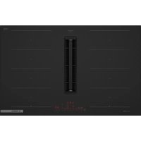
| Product type | Induction cooker |
| Dimensions (W x D x H) | 60 x 60 x 85 cm |
| Number of cooking zones | 4 induction cooking zones |
| Total power | 7400 W |
| Special features | Boost, timer, pan detection |
| Control type | Touch control panel |
| Energy consumption | Energy class A |
| Weight | 38 kg |
| Surface material | Ceramic glass |
| Safety system | Automatic shut-off, child safety |
| Maintenance | Easy cleaning thanks to smooth surface |
| Warranty | 2 years |
Frequently Asked Questions - PIE611B15E BOSCH
User questions about PIE611B15E BOSCH
0 question about this device. Answer the ones you know or ask your own.
Ask a new question about this device
Download the instructions for your Cooker in PDF format for free! Find your manual PIE611B15E - BOSCH and take your electronic device back in hand. On this page are published all the documents necessary for the use of your device. PIE611B15E by BOSCH.
USER MANUAL PIE611B15E BOSCH
m = 311
27
29
m = 311
31
m = 311

33
34
35
36
m = 311 ;
38
m = 311
40
41
42
43
m = 311
45
m = 311
47
m = 311
49
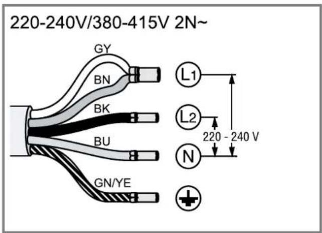
220-240V/380-415V 2N~
50
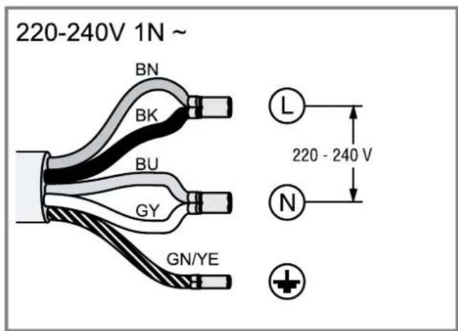
220-240V 1N~
51
es
After unpacking all parts, check for any damage in transit and completeness of the delivery. Fig. 1
QR code for the installation video
This is were you will find the QR code for the installation video. Fig. 2
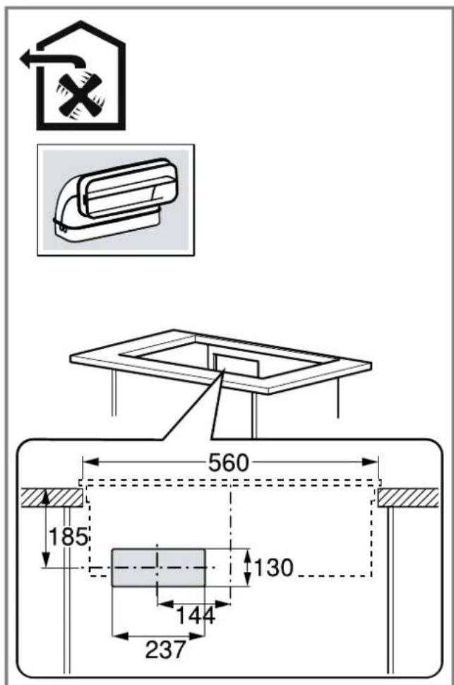
Appliance dimensions
You will find the dimensions of the appliance here Fig. 1
Installation dimensions for flat duct bends
This is where you can find an overview of the installation dimensions for the flat duct bends.
Side view:
→Fig.4,→Fig.5,→Fig.6
Front view:
Fig. 7
Installation variants
This is where you can find an overview of the different installation variants.
Odour filter and adapter for circulating-air mode:
Fig. 8
Acoustics filter and seal for air extraction mode:
Fjg. 9
Note: Channels suitable for installation can be obtained from customer service, our website or from specialist retailers.
Safety clearances
Comply with the safety clearances for the appliance.
Clearances to the overflow container:
Fig. 10
Position of the overflow container:
Fig. 11
The performance is optimal at a clearance of 50mm between the unit back panel and the wall. The performance is reduced at a smaller clearance.
Fig. 12
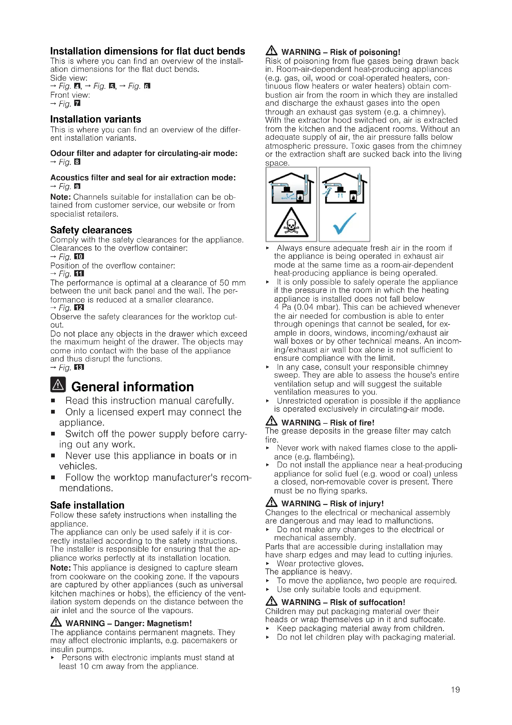
Observe the safety clearances for the worktop cutout.
Do not place any objects in the drawer which exceed the maximum height of the drawer. The objects may come into contact with the base of the appliance and thus disrupt the functions.
→Fig.

General information
- Read this instruction manual carefully.
Only a licensed expert may connect the appliance. - Switch off the power supply before carrying out any work.
- Never use this appliance in boats or in vehicles.
- Follow the worktop manufacturer's recommendations.
Safe installation
Follow these safety instructions when installing the appliance.
The appliance can only be used safely if it is correctly installed according to the safety instructions. The installer is responsible for ensuring that the appliance works perfectly at its installation location.
Note: This appliance is designed to capture steam from cookware on the cooking zone. If the vapours are captured by other appliances (such as universal kitchen machines or hobs), the efficiency of the ventilation system depends on the distance between the air inlet and the source of the vapours.

WARNING - Danger: Magnetism!
The appliance contains permanent magnets. They may affect electronic implants, e.g. pacemakers or insulin pumps.
Persons with electronic implants must stand at least 10cm away from the appliance.
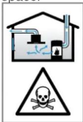
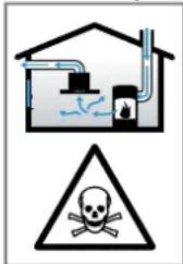
WARNING - Risk of poisoning!
Risk of poisoning from flue gases being drawn back in. Room-air-dependent heat-producing appliances (e.g. gas, oil, wood or coal-operated heaters, continuous flow heaters or water heaters) obtain combustion air from the room in which they are installed and discharge the exhaust gases into the open through an exhaust gas system (e.g. a chimney). With the extractor hood switched on, air is extracted from the kitchen and the adjacent rooms. Without an adequate supply of air, the air pressure falls below atmospheric pressure. Toxic gases from the chimney or the extraction shaft are sucked back into the living space.
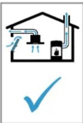
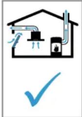
Always ensure adequate fresh air in the room if the appliance is being operated in exhaust air mode at the same time as a room-air-dependent heat-producing appliance is being operated.
- It is only possible to safely operate the appliance if the pressure in the room in which the heating appliance is installed does not fall below 4 Pa (0.04 mbar). This can be achieved whenever the air needed for combustion is able to enter through openings that cannot be sealed, for example in doors, windows, incoming/exhaust air wall boxes or by other technical means. An incoming/exhaust air wall box alone is not sufficient to ensure compliance with the limit.
In any case, consult your responsible chimney sweep. They are able to assess the house's entire ventilation setup and will suggest the suitable ventilation measures to you.
Unrestricted operation is possible if the appliance is operated exclusively in circulating-air mode.
WARNING - Risk of fire!
The grease deposits in the grease filter may catch fire.
- Never work with naked flames close to the appliance (e.g. flambéing).
- Do not install the appliance near a heat-producing appliance for solid fuel (e.g. wood or coal) unless a closed, non-removable cover is present. There must be no flying sparks.
WARNING - Risk of injury!
Changes to the electrical or mechanical assembly are dangerous and may lead to malfunctions.
- Do not make any changes to the electrical or mechanical assembly.
Parts that are accessible during installation may have sharp edges and may lead to cutting injuries.
Wear protective gloves.
The appliance is heavy.
To move the appliance, two people are required.
Use only suitable tools and equipment.
WARNING - Risk of suffocation!
Children may put packaging material over their heads or wrap themselves up in it and suffocate.
- Keep packaging material away from children.
Do not let children play with packaging material.
WARNING - Risk of poisoning!
Risk of poisoning from flue gases being drawn back in.
- Do not emit the exhaust air into a smoke or exhaust gas flue that is in operation.
- Do not emit the exhaust air into a shaft that is used to ventilate installation rooms for heat-producing appliances.
If the exhaust air is to be conveyed into a smoke or exhaust gas flue, you must obtain the consent of the heating engineer responsible.
Risk of poisoning from flue gases being drawn back in.
If an extractor hood with an open-flued heat production source is installed, the power supply for the extractor hood must be provided with a suitable safety switch.
Information about the electrical connection
In order to safely connect the appliance to the electrical system, follow these instructions.
WARNING - Risk of electric shock!
It must always be possible to disconnect the appliance from the electricity supply. The appliance must only be connected to a mains socket that has been installed correctly.
An all-pole isolating switch must be integrated into the permanent electrical installation in accordance with the conditions of overvoltage category III and in accordance with the installation regulations.
The permanent electrical installation must only be wired by a professional electrician. We recommend installing a residual-current circuit breaker (RCCB) in the appliance's power supply circuit.
- Do not kink or trap the connection cable, and keep it away from sharp edges.
- Route the connection cable in such a way that it does not touch the hot casing.
- Use only the connection cable that is supplied with the appliance or is provided by technical after-sales service.
This appliance complies with the EC interference suppression regulations.
The appliance corresponds to protection class 1. You should therefore only use the appliance with a protective earth connection.
The manufacturer shall assume no liability for malfunctions or damage resulting from incorrect electrical wiring.
Preparing the electrical connection
Requirement: Only after-sales service staff who have been trained accordingly may carry out work on the inside of the appliance or replace the power cord.
- Observe the information about the electrical connection.
An incorrect installation, an improper installation or connection invalidates the warranty. - If a longer mains power cable is required, contact the after-sales service. Connecting cables up to 2.20m are available.
- On appliances without a preinstalled cable, insert the power cable into the mains socket.
Opening the mains socket
- Use a screwdriver to lift the cover of the mains outlet.
$$ \rightarrow F i g. 1 4 $$
Preparing the mains socket
- Undo the screw.
$$ \rightarrow \text {F i g .} $$
- Use a screwdriver to lift the strain relief.
$$ \rightarrow \text {F i g .} 1 6 $$
- Loosen the strain relief.
$$ \rightarrow \text {F i g .} $$
Connecting the cable to the mains socket
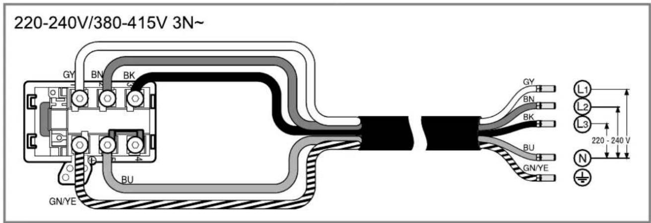
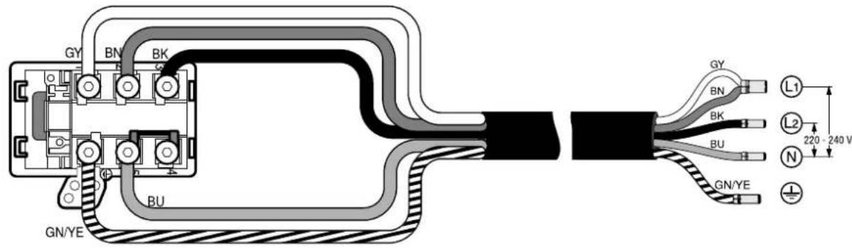
- For 3N connect the cable to the mains socket in accordance with the following figure.
$$ \rightarrow \text {F i g .} 1 8 $$
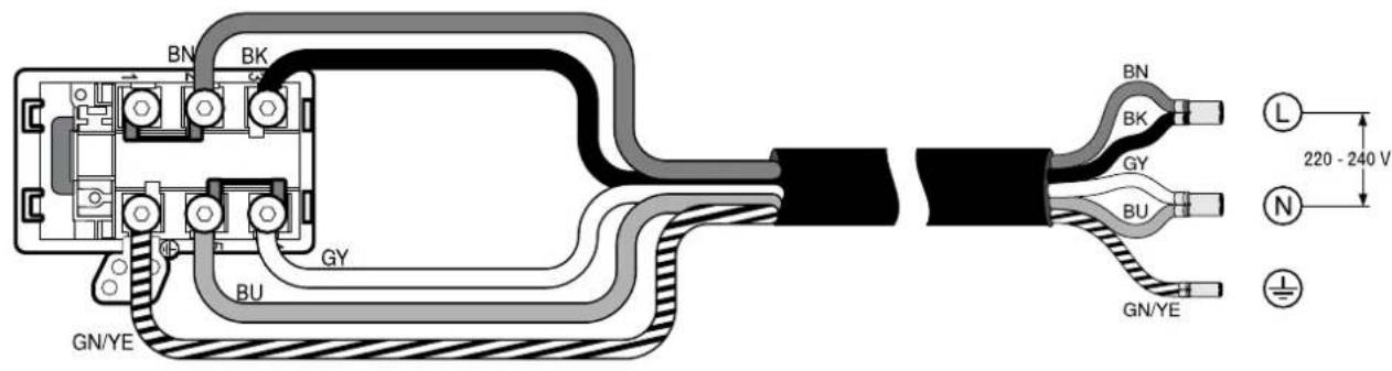
- For 2 N ,connect the cable to the mains socket in accordance with the following figure.
$$ \rightarrow \text {F i g .} \tag {19} $$
- For 1 N, connect the cable to the mains socket in accordance with the following figure.
$$ \rightarrow \text {F i g .} 2 0 $$
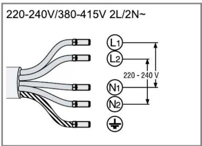
- For 2L / 2N connect the cable to the mains socket in accordance with the following figure.
$$ \rightarrow \text {F i g .} 2 1 $$
-
Note the colours of the cables.
-
BN: Brown
- BU: Blue
- GN/YE: Yellow and green
- BK: Black
-
GY: Grey
-
If required, install the enclosed copper bridges in accordance with the connection diagram.
- Connect the cables and then tighten the screws of the mains socket.
- For a 1N^ or 2L/2N connection in accordance with the connection diagram, 1 corresponds to the fan motor.
- For a 2N^ / 3N^ connection, phase L1 (grey) corresponds to the fan motor.
Secure the cable in the mains socket
- Use the strain relief to secure the power cable in place.
-
Tighten the screw at the correct position.
-
Do not use a cordless screwdriver.
$$ \rightarrow \text {F i g .} $$
- To facilitate closing the mains socket, arrange the cables in the central area of the mains socket.
- Close the cover on the mains socket.
Instructions for the exhaust air pipe
The appliance manufacturer does not provide any warranty for faults attributable to the pipeline.
Use a short, straight exhaust air pipe with as large a pipe diameter as possible.
- Long, rough exhaust air pipes, many pipe bends or small pipe diameters reduce the suction power and increase the fan noise.
Use an exhaust air pipe that is made of non-combustible material.
To prevent condensate from returning, fit the exhaust pipe with a 1^ gradient from the appliance.
Flat ducts
Use flat ducts with an inner cross-section that corresponds to the diameter of the round pipes:
Diameter of 150~mm corresponds to approx. 177~cm^2
Use sealing strips for different pipe diameters.
- Do not use any flat ducts with sharp bends.
Round pipes
Round pipes with an inner diameter of 150~mm
Instructions for the air extraction mode
For air extraction mode, a one-way flap should be installed.
Notes
If a one-way flap is not included with the appliance, one can be ordered from a specialist retailer.
If the exhaust air is conveyed through the external wall, a telescopic duct should be used.
Checking the units
- Check whether the fitted unit is level and has sufficient load-bearing capacity.
The maximum weight of the appliance is approx. 25kg
The worktop into which you are fitting the appliance must be able to withstand loads of approx. 60kg
- Ensure that the stability of the fitted unit is also guaranteed following cut-out work.
-
Use suitable substructures to ensure the load-bearing capacity and stability, particularly in the case of thin worktops.
-
Take the appliance weight, including additional load, into consideration.
-
Use heat-resistant and moisture-resistant reinforcement material.
-
Ensure that the fitted unit is heat-resistant up to 90^ .
- Do not support any other appliances, e.g. ovens, refrigerators, dishwashers or washing machines.
- Only check that the appliance is level once it has been installed in the installation opening.
- You can freely select the clearance to a top cabinet. In doing so, take into consideration the ease of use and ergonomics when using the plate.
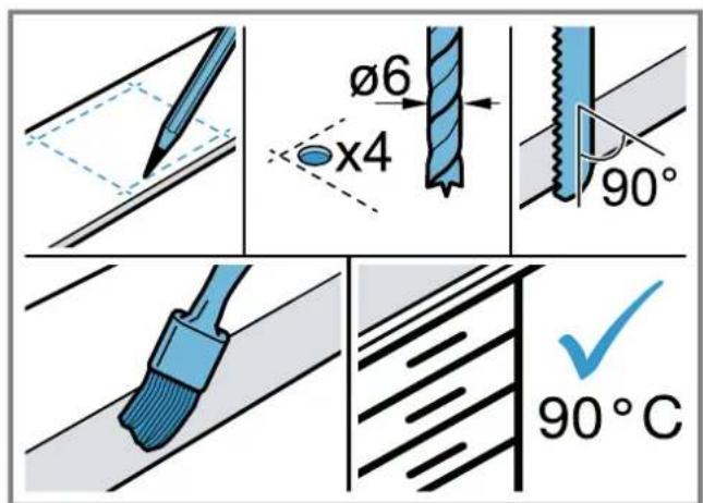
Preparing the units
Requirement: The fitted units are heat-resistant up to 90^
$$ \rightarrow F i g. 1 3 $$
- Mark the unit cut-out in accordance with the installation diagram.
- Drill four holes with a diameter of 6mm Fig. 23
- Ensure that the angle of the cut surface to the worktop is 90^ .
$$ \rightarrow \text {F i g .} 2 3 $$
Observing the minimum clearances when installing above a drawer
- When removing the overflow container on integrated appliances, take the minimum clearances into consideration.
$$ \rightarrow F i g. \quad 1 0 $$
- Observe the position of the overflow container.
$$ \rightarrow \text {F i g .} $$
Preparing the unit for circulating-air mode with the adapter
Notes
We do not recommend to install on a nonthermally insulated outer wall or above a cold floor ( ≥ 0.5W / m^2 C).
Air outlets must not be directed at other appliances, they should be parted by a separation panel. If you cannot install any separation panels, refer to other installation types..
- Observe the relevant dimensions when combining with the adapter for the cut-out in the back wall. Fig. 24
- Measure the thickness of the worktop. Transfer the measurement to the template and draw a line that corresponds to it.
$$ \rightarrow \text {F i g .} 2 5 $$
- Cut the template along the marked line for worktop thickness A, the cut centre line B and the reference line to the inner air outlet C.
-
Mark the centre of the cut-out in the worktop as the centre line on the back panel of the unit. Fig. 26
-
Align the template to the centre line of the back panel of the unit and to the lower edge of the work surface.
- Use the template to make the cut-out in the back panel.
- After making the cut-outs, remove any shavings.
- Seal the cut surfaces so that they are heat-resistant and waterproof.
$$ \rightarrow \text {F i g .} $$
Ventilation
-
In circulating-air mode, establish an air outlet in the unit's plinth.
-
Provide a minimum air outlet cross-section of approx. 400~cm^2
- Make the outlet opening in the base panel as large as possible in order to keep draughts and noise to a minimum.
-
Make the outlet opening by shortening the plinth or by using suitable ventilation grilles or a lamellar plinth.
-
To guarantee that the appliance works correctly, ventilate the hob appropriately via an air outlet with a minimum cross-section of 200~cm^2 in the base unit.
Installing an appliance featuring circulating-air mode with adapter
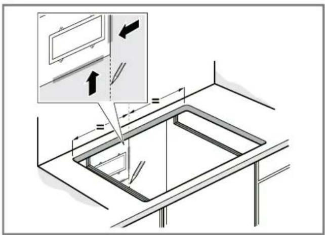
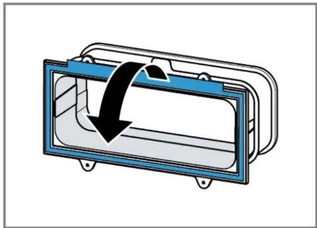
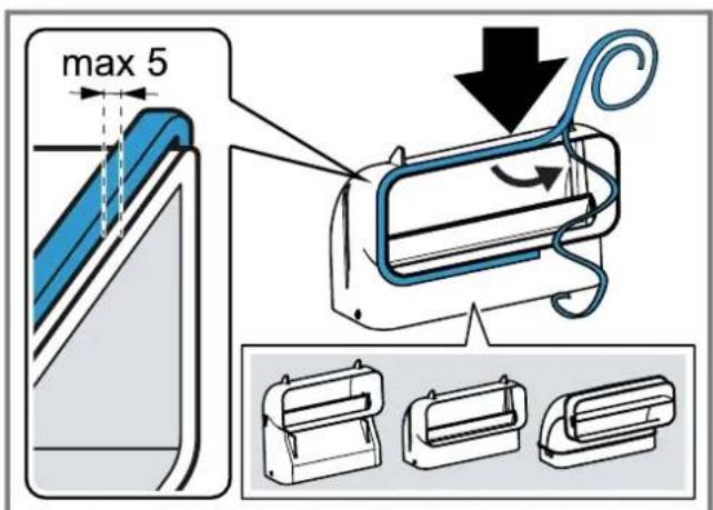
Attaching the seal to the adapter
- Attach the seal to the adapter with max. 5 mm to the edge.
$$ \rightarrow \text {F i g .} 2 7 $$
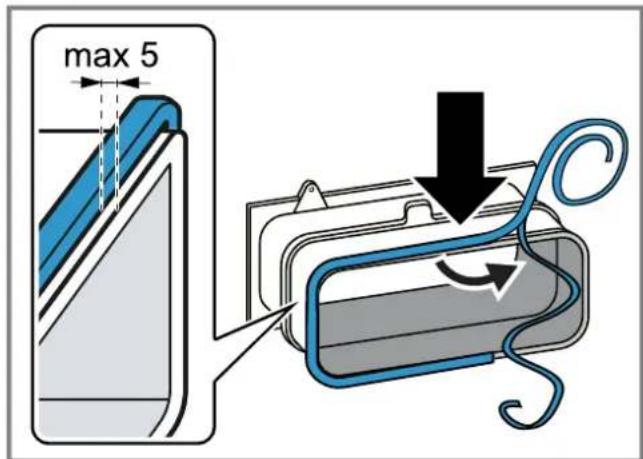
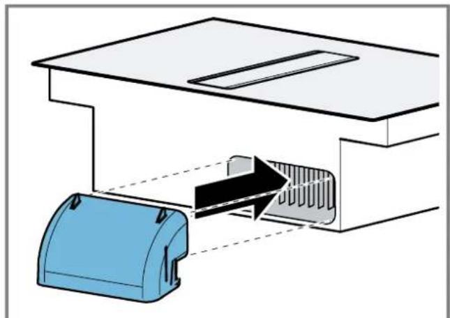
Attaching the adapter
- Clean and degrease the adhesive surface around the cut-out in the unit's back panel.
- Insert the adapter into the outlet opening on the rear of the hob.
$$ \rightarrow \text {F i g .} 2 8 $$
- Remove the adhesive tape's protective film from the adapter.
$$ \rightarrow \text {F i g .} 2 9 $$
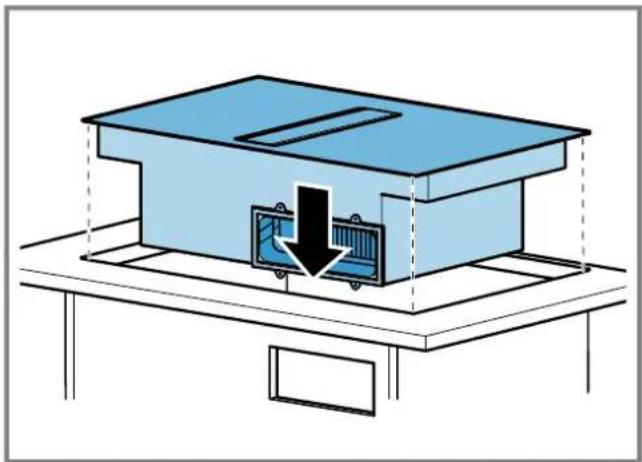
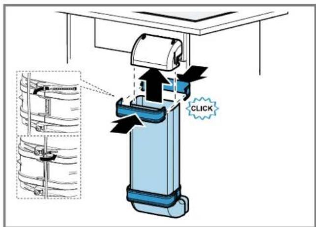
Inserting the appliance into the worktop cut-out
- Ensure that the connection cable is connected to the appliance.
- Carefully insert the appliance into the worktop cutout.
$$ \rightarrow \text {F i g .} 3 0 $$
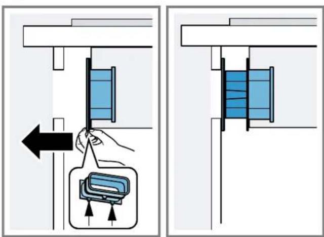
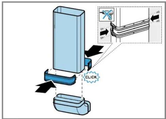
Securing the adapter
- Hold the adapter at the central holder and use the side holders to slide it towards the unit's back panel in the base unit, then affix it.
$$ \rightarrow F i g. \quad 3 1 $$
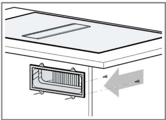
- If required, also use screws to secure it.
$$ \rightarrow \text {F i g .} 3 2 $$
Preparing the unit for circulating-air mode with a circulating-air duct
-
If required, remove the unit's back wall.
-
Observe the relevant dimensions when combining with the flat duct elbow for the cut-out in the back wall.
$$ \rightarrow \text {F i g .} \quad 3 3 $$
-
In circulating-air mode, establish an air outlet in the unit's plinth.
-
Provide a minimum air outlet cross-section of approx. 400~cm^2
-
Make the outlet opening in the base panel as large as possible in order to keep draughts and noise to a minimum.
-
Make the outlet opening by shortening the plinth or by using suitable ventilation grilles or a lamellar plinth.
-
To guarantee that the appliance works correctly, ventilate the hob appropriately via an air outlet with a minimum cross-section of 200~cm^2 in the base unit.
- After making the cut-outs, remove any shavings.
- Seal the cut surfaces so that they are heat-resistant and waterproof.
$$ \rightarrow \text {F i g .} 2 3 $$
Installing the appliance for air recirculation mode with circulating-air duct
- For circulating-air mode, use the seal, the circulating-air duct, the diffuser and the odour filter.
- Observe the dimensions for the different flat duct bends. Page 19
Securing the seal
- Secure the enclosed seal on the flat duct elbow at a maximum of 5mm from the edge.
$$ \rightarrow \text {F i g .} \quad 3 4 $$
Inserting the flat duct elbow
$$ \rightarrow F i g. \quad \boxed {R 5} $$
- Insert the flat duct elbow into the outlet opening on the rear of the appliance.
Inserting the appliance into the worktop cut-out
- Ensure that the connection cable is connected to the appliance.
- Carefully insert the appliance into the worktop cutout.
$$ \rightarrow \text {F i g .} 3 6 $$
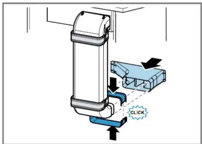
Establishing the pipework between the appliance and the diffuser
-
Connect the components of the circulating-air duct to each other.
-
Secure the flat duct pipe connector by engaging it in place.
- For an additional fixing, screw the flat duct pipe connector together using 4 × PT 4 × 8 ~mm screws for plastic.
$$ \rightarrow \text {F i g .} \quad 3 7 $$
$$ \rightarrow \text {F i g .} 3 8 $$
$$ \rightarrow \text {F i g .} \quad 3 9 $$
- Connect the circulating-air duct to the flat duct elbow on the rear of the hob.
- Connect the diffuser to the circulating-air duct.
Preparing the unit for air extraction mode
- If required, remove the unit's back wall.
- Observe the relevant dimensions when combining with a flat duct elbow for the cut-out in the back wall.
$$ \rightarrow F i g. \boxed {2 0} $$
- After making the cut-outs, remove any shavings.
- Seal the cut surfaces so that they are heat-resistant and waterproof.
$$ \rightarrow F i g. \quad 4 1 $$
Install the appliance for air extraction mode
- For air extraction mode, use the seal and the acoustics filters.
- Observe the instructions for the exhaust air pipe. Page 20
Securing the seal
- Secure the enclosed seal on the flat duct elbow at a maximum of 5mm from the edge.
$$ \rightarrow F i g. \quad 3 4 $$
Establishing the piping
- Insert the flat duct elbow into the outlet opening on the rear of the appliance.
$$ \rightarrow \text {F i g .} \quad 3 5 $$
- If required, install additional piping elements.
Inserting the appliance into the worktop cut-out
- Ensure that the connection cable is connected to the appliance.
- Carefully insert the appliance into the worktop cutout.
$$ \rightarrow \text {F i g .} 3 6 $$
Connecting the exhaust air pipe
- Secure the exhaust air pipe to the flat duct bend.
- Establish the connection to the exhaust air opening.
- Seal the joints appropriately.
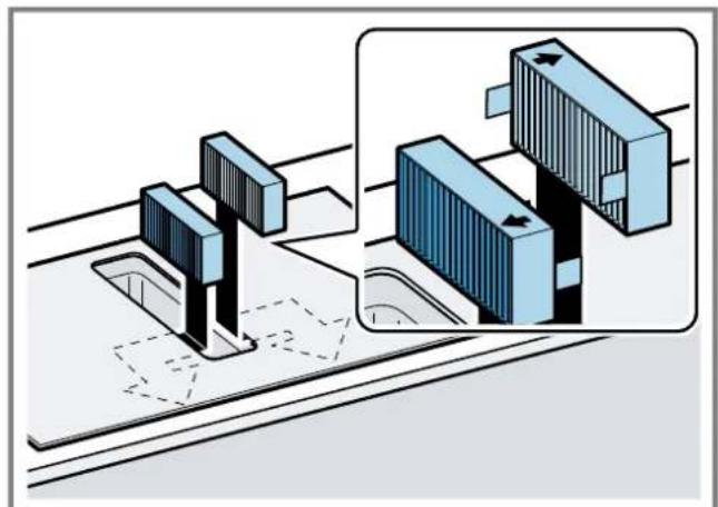
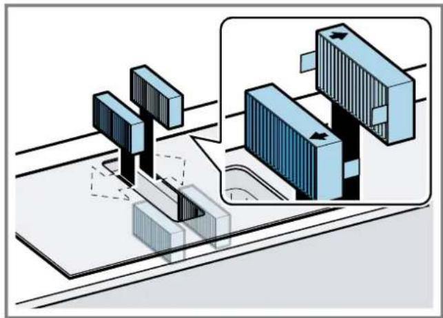
Inserting filters
Note: For circulating-air mode, insert the odour filters.
For air extraction mode, insert the acoustics filters.
- Observe the filters' air flow direction.
- Insert two of the filters into the left and right of the appliance, and slide them forwards.
$$ \rightarrow \text {F i g .} $$
$$ \rightarrow \text {F i g .} \quad 4 8 $$
- Insert the other filters into the left and right of the appliance.
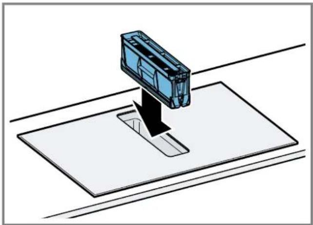
Inserting grease filters
- Insert the grease filter.
$$ \rightarrow \text {F i g .} 4 4 $$
Establishing the connection to the power supply
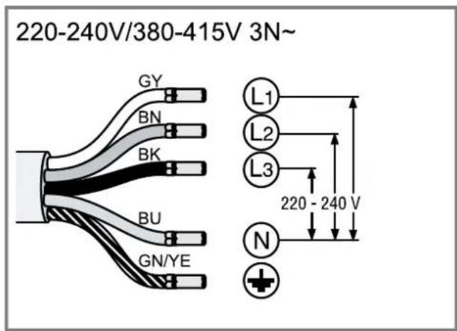
- Observe the connection data on the rating plate.
- For 3N connect the cable to the mains socket in accordance with the figure.
$$ \rightarrow \text {F i g .} \quad 4 5 $$
- For 2N connect the cable to the mains socket in accordance with the figure.
$$ \rightarrow \text {F i g .} \quad 4 6 $$
- For 1 N, connect the cable to the mains socket in accordance with the figure.
$$ \rightarrow \text {F i g .} \quad 4 7 $$
- For 2L / 2N connect the cable to the mains socket in accordance with the figure.
$$ \rightarrow \text {F i g .} \quad 4 8 $$
-
Note the colours of the cables.
-
BN: Brown
- BU: Blue
- GN/YE: Yellow and green
- BK: Black
-
GY: Grey
-
If required, arrange the supplied wire end ferrules differently depending on the type of connection.
- To connect two cables, if required, use a wire end ferrule.
Shorten the wires.
- Remove the insulation.
Checking the function
- Switch on the appliance.
- If 0400 Eogts up the appliance is not connected correctly. "Checking and correcting the electrical connection", Page 23
- If no faults appear in the appliance's display, use the operating instructions to check that the ventilation is working.
Checking and correcting the electrical connection
- Disconnect the appliance from the power supply.
- Check whether the connection to the appliance and the building-side connection correspond to the connection diagram in these installation instructions. "Preparing the electrical connection", Page 20 "Establishing the connection to the power supply", Page 22
3.For 3N observe the following figure. Fig.49
4.For 2N observe the following figure. Fig.50
5.For 1 N, observe the following figure. Fig.51
Switching the display for air extraction mode
- If required for the air extraction mode and the air recirculation mode, change the display of the electronic control in the basic settings.
- Observe the basic settings section in the instruction manual.
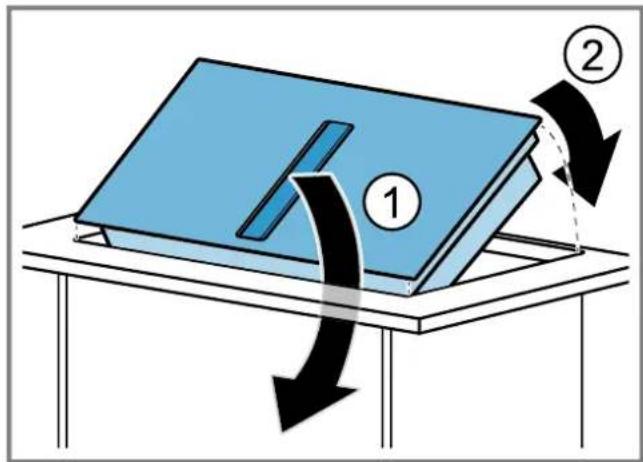
Removing the appliance
ATTENTION!
Tools may damage the appliance frame.
Do not perish out the appliance from above.
1. Disconnect the appliance from the power supply.
2. Remove the exhaust air duct or undo the circulating-air connections.
3. Push out the appliance from below.
fr
ADVARSEL-Fare for forgiving!
ADVARSEL - Brandfare!
Fedtaflejringer i fedtfiltret kan blive antaendt.
ADVARSEL-Fare for forgiving!
Fastgoring at taeling
- Fastgor den medfolgende taeling pa fladkanalbogen maks. 5 mm fra kanten. Fig.34
Fastgoring at taeling
- Fastgor den medfolgende taeling pa fladkanalbogeningen maks. 5 mm fra kanten. Fig.34
Monteringsmal for flat rorbend
Her finner du en oversikt over monteringsmalene for flate rorbend.
Sett fra sider:
→Fig.4→Fig.5→Fig.6
Sett fortra:
Fig. 7
ADVARSEL-Fare for forgiving!
ADVARSEL-Fare for forgiving!
Ynoeic yia Tov aywyo aaywnc Tou aepa
O kataaekuaoTHC TNC oukeunc dev avaalapavei kaia euhvni TIC diapptupic, nou ofeilovtai OTO tmuTsw owAnvWv.
XpooiopoioTe evav kovTo, eueuypmao oAAnva Eepiaou u eia kaTaTO duvatov eyaan diaeTPO OAnva.
Oi eyaai, Tpaeeic oanvce anaywng Tou aepa, OI naaeK aumuace n oikpec diaetpoi oanvW Ueivouv Tnv ixuc avappoonc kai auqavouv Tov 0puo tou avmuotnpa.
Xpoaioiopoioe evav oawiva Eaepiou aio uEuphiKTo uAIko.
Tia va aonoouyete nV eIIOptpooh ouuukwpatoc, TOnoEETnoTe Tov oAAnva Eeapioou ano Tn epia Tnc ouokcunc eKion 1°.
EnirEaKovlaia
Xpnoiopoioite enitea kavai, two oioiw n eowtepiok diatoan avtioxei otn diaeppto two opoyyuaw owv:
H diapetoc 150 mm avtiotoxie i nepiou oe 177 cm2.
- 2E nepinwnnou diaepouov oiaetpoi twv owAnvw tooTheeawipdec steyavoinonc.
Mn xpoaiopoinieite einieδa kavaiia μe anotouec aayc kateuuvong.
Tpoyyuoi oawlvec
Xpnoiopoieite otpoyuouc oawhvec iia eowtepi kδiμεtpo a10 150 mm.
Ynoeic yia Tn Iaoupyia Eaepioou
Be3oNaChbIe paCToHHN
Co6nIpaTe 6e3oNaChbIe pacCTOaHINn IINBaWero np6o- pa.
PacctoHHe Do EMKoCTn DnA CnBa NnHHe KnKocTn:
→PUC.10
PacnonoXeHne EMKoCTn DnA CNBa NnHei KIOCTn:
→PUC.11
OttmaBnaM OUHCTb DOCTnraeTcA,ecn paCctoHne MeJy 3aDHeN CTeHKn Me6eN IN CTeHOI COCTaBnEET 50 MM. Pn HeOCTaTOOH PACCToHH MOnHOCt b CHINKaET- C
→PUC.12
BbIepKNaBte 6e3oNaChbIe pacCTOaHH npN BblOnHeHHn Bblpe3a B cToJIeHHuE.
He KlaIaIte B BbIbNkHoi RnK npeMTeB, BbICota KOTOp bIX npeBbIwaet MaKcImaJIbHyIO BbICOTy Rnika. TaKne npEeMetb MOrT yInpaTbcB OCHOBaHne npnbopa, TEm caMbIM MeWAr erO paBoTe.
→PUC.13

O6uNe yka3aHnA
BHHMaTeIbHo npOHTaIte daHHepe pyKOBODCTBO.
ToIbKO KBaIIHΦIuPObaHHbI CneuaJIInCT MoKET BbIINHHTb NOkJIIOueHHe IprIbopa.
Ipeed npoBeHnem IIO6bix pa60T OTKHOHTe noauy 3JKeKtpo3Heprn.
3anpeaaetcHcnoB3oBaTb np6op Ha loKax HnB aBTOMO6nax.
Co6HoJaTe peKOMeHdaqun npOn3BOHTeJI CTOJeuHnUbl.
Be30nacHocTb npn MOHTaKe
Pny yctaHOBKe np6opacobnoaTe daHHbIe yka3aHnI NO texHnke 6e3oNaChOCTn.
Be3onacHocTb 3KcPnyataunrapaHTnpyETcaToIbKO npn KbaIINpOBAHHoY cTaHOBKe C co6NIOHeHNm HCTpyKuIN NO MOHTaKy. 3a npAInbHOCTb yCTaHOBKN OTBeTCTBeHHOCt b HecET YcTAHOBUnK.
3aMeTka: 3OT np6op npedHa3Hauen dIy ynaBnBaHH naPob Pn npiroTOBHeHH B nocye, cToIe Ha 3OHe HarpEba. Ecn npbl npOn3BOaRdI pyrIe np6Opbl (HanpImep, KxOHbIe KOMbAHbI NII BapOHyIe NaHeII), 3ΦΦeKTHBHOCTb CNTeMb BEHTnAun 6yDet 3aBcEt b OT pacCToHHMaKJy BO3dyX03a6Opom m MeCTOM BbIXOda napOB.
I NPEyIpeXJEHNE -OnaCHOCTb:MarHeTn3M!
Pn6bOp cOepKHT NOCToHHBle MaHHTbl. OHN MoYr BO3-DeiCTBOBaTb Ha BxHBJeHHBie 3JeKTPOHHBle np6bOpbl, HApimep, Ha KapDIOCTMMyIaTOpbl nnn HHCyINHOBBie NOMbl.
IiucamC3JIeKTKPOHHbIMNIMnlaHTaTaMn 3anpeuaetc np6nKaTbcaK np6bopy 6nHexe, yem Ha 10 cm.
NPEyPExKDEHNE -OnacHoctb OTPaBHeHnA!
Brahytbe 6bpatHO Otpa6oTaBwne Ra3bl Moryt cTaTb npuHnHoi OtpaBHeHH. NCTOCHNKN PnAmEHn C NOBODOM BO3DyxaH3 NOMEeHHa (HaNPmep, pa6oTaUoJne Ha r3e, XKnKOMToNNBe, ApOBax nIN yrIe HArpeBaTeEN, IpOTOnHbE BoHOHarpeBaTeEN, 60nIepbI) nONyauKT B03dyx DNJIcKnRaHH
TOnJIbBa N3 NOMeUeHn, rIe OHN yCTaHOBHeHb, a OTPa6oTbUWe Ra3bI OTXoJr Tyepe3 BByTAAKHyO CnCTEmy (HaNPmep, BByTAKKHyIO Tpy6y) n3 NOMeUeHn Ha yLIuCy. Bo BpemraPabOTbI BByTAAKKn I3 KxHN IpaONlaRAOUIXc PdOM NOMeUeHN yDAJIReTCB BO3dyx. Be3 DOCTaOuHOro pNtOKa ATMocΦepHOrO BO3dyxA B NOMeUeHne DaBJIeHne MOKeT YMeHbWHTbcR, IN TOKCHNbIE Ra3bl N3 DbIMOXoJa HIN BEHTIIaun HAHyT BCaCbIbATbcr O6paTHO B XInIOe NOMeUeHne.
Bcerda obecneuBaIte npitOK doCTaTOHOro KOJIueCTBa BO3dyxa, ecIn npin6Op nNcTouHnK PIIaMeHN C NODBOOM BO3dyxa n3 NOMEUeHH pa6OtaHOT ONDHOpeMeHNO B peJHKMe OTbOda BO3dyxa.
Be3onacbIM dIgEKcNpyataun np6opacOTkpbItbIM nIamaHem RnRETCaONHXeHne DaBHeHHe He 6Oonee YEm Ha4Pa(0,04M6ap).3TO MoKeT 6bTB DoCTnHyTo,ecn Tpe6yEmbldCINrAHHBO3DyX 6yTeNocTyNaTbYepe3 He3aKpbBaEMbIE OTBepTna,HaNPmEp,BDbepx,OKHax,C NOMoBcIO CTEHHO KOpOa CnCTeMb IpNToka/OTBoDa BO3Dyxa ININ HbIX TEXNHuecknx Mep.Bcero OINn pINTOHO-BBITAAHKnIaanHe ObecneHT rapaHTNO CO6IIIODeHn PpeDJIbHOrO 3HaueHn.
B liobocntyaunno6paauuTceb3a coBeTom K KomteHTHomy nuy,OTBeTCTBeHHOMy 3a 3KcPiyaTuHIO ouNCTky Tpy6,CnocO6HOMy OueHNTb BEHTNIJIauoHHUo CnCTemy Bcero Doma n npedNoXtB Bam peIeHne no pniHATNO COOTBeTCTByUOxN Mep.
Ecn np6op pa6oTaET NCKIIOHTeBHO BpeKIMe CUPKyJIaUN BO3Dyxa,TO 3KcNpyataunn BO3MOxHa 6e3 OrpaHHeHH.
I PNEyIPEXJEHNE -Onachoctb Bo3ropaHHa!
OTnoKeHnJXnpaB XnpoynabNBAuOeM FnIbTpE MOryT BCnblxHyTb.
Hnkorga HpepaotateCOTKpbTbIMnIaMeHemPdOM C np6opom (Haepmep, pAm6npoBaHne).
Pn6bop MoKHO yCTaHaBnBaTb B6H3N nCTOHNka DnCkHraHn TBepDOro TOnnBa (HAnpMep, dpoBa HnIyrolb), ecIn npedycmTopeHa uehha HecbemHa 3a- uHTnaHn NaHeB. He donKHo 6bItb pa3netaOuNXcNckp.
I NPEUYPEXKDEHNE -OnacHocTb TpaBMnpoBaHHa!
H3MeHeHne MexaHuecko Hn 3NeKtpueecko KOHcTpkyu MoKet CTaTb HCTOuyHKOM ONaCHOCTN IN PpNBcETN K BblxOdy np6opa n3 cTpor.
- 13MeHHeMexaHnueeCKo INI 3JIeKTPnueeCKO KOHCTpyKcnn 3aIpeUeHO.
Ietann,OTKpbItbIe npn MOHTaKe,MOyT 6bITb OCTpbIMN npnbecTN K nope3aM.
- IcnoIb3yIte 3aIuNTHbIe nepuAtKn.
PnIbOp TAnKeJIbI.
Iraero nepemeseHHnoTpebyOTc2yeNoBeKa. - IcnoIb3yIe ToIbKO NoIxOJaUHe BCnOMaTeJIbHbIe cpeIcTBA.
A NPEdYIpeXJEHNE -OnachocTb ydysb!
TeMOry3aBepHyTbCByyNaKOBOHbIMaTePnAn HnHa-DeTberoce6eHa roNoBvN3aOxHyTbCra.
He noDnyckaTe DeTe K ynaKOBouHomy MaTePnany.
He no3BOJIaIe Te DeTAM IrpaTb C yIaNKOBOUHbIM MaTePnaJOM.
I PPEyIPEKJEHNE -Onachocb oTpabJeHHa!
Brahytble obaPATHO B NOMeHne OtpaOTabuHne ra3bl MoryT CTaTB npuHNO OTPaBHeHH.
BbTJHKHO B03DyH He DOnJIeH BByXoNtB uepe3 DbIMOBYIO Tpy6y HnB03DyXoBOO npn Hx 3KcnnyaTaun.
Длг OTBDA BByTJHHO BO3DyHa He CJIeDyET NcIOnIb3O-BaTb BEHTKaHAn, CnyJkaUIMДЯ BeHTnlaUIN NOMEueHIN, B KOTOpbIX YCTaHOBHeHb INCTOuHNKII PJIaMeHN.
PnIOKnOueHNNBbTJHKNHeNCNoJIb3yeMOMyDbIMoxOdy,HeoXoDIMO NOyUHTb pa3peuHne B CneuaJIb-HoINHCTaHcH,OTBeauOeJ3a 3KcIpyaTaunHO uHCTKy Tpy6.
BTHyTbe 6paTHo B NOMEUHHe OtpaOToABuHne ra3bl MOryt CTaTB npuHnOH OTPaBJIeHH.
PnU yCTaHOBKe BbITJAKKIN NOMeueHnAX, Ie npCytCTByET NCTOCHN K PnAmEH C NOBODOM BO3dyXa N3 NOMeIeHNA, CNCTema NODaUN NITAHN BbITAAKKN DOJIHXA 6bITb 06OpyDoBaHa FyHKnei abapmHOro OTKnIOUeHn.
Yka3aHn no noKnIOueHHo K 3JIeKTpocetN
ДябezоносогиpoДКИчeyн npH6opaK 3NeKtpocetN co6HIOdaIte daHHbIe INCHTpkyuIN.
I PEPENPEKDEHNE -Onachoctb npaHexnnaektpnueckm TOKOM!
CneNyet o6ecneHb BO3MOxHOCb OTKHoueHn npnbopa ot 3JIeKtpocetN B IHOBOMoMeHT. 3TOI np6Op MOxHO IOKIOUOATb K cETN TObKO Upe3 npaBnIbHO yCTaHOBNeHHyO paCnpedeIeNTbHyO Kopo6Ky.
B ctaioHapHo 3neKtponpoBoDke Heo6xoDIMO npedyCMOTpeTb CnueaIbHbI BblIOHaTeNb Ira pa3MbkaHnaBCex nIOIOcOB corlaCHO ycIOBnAM kateropn NepeHaipxKeHHI IIN corlaCHO ycIOBnAM MOHTaKa.
IoiKluoyehne ctaunohapHoro 3eKtpoobopyoBaHHn DOJXHO pOni3BOIDtBCr TOnbKO KBaIIuNpOBoHHbIM 3eKtpnKOM.Mb peKomeHdyem yCTaHOBt b yCTpoCTBO 3aUHTHO OTKluoyehn (Y3O) B 3eKtpuecko ce nni CHa6KeHHn Pnp6OpOB.
PpocneIte, YTo6bI cTeBOI Ka6eJIb He 6bl 3aKaT, HpeerH6anr HaxOHNCR BdaJIN OT OCTpbIX KpOMOK.
IpoKnaDbBaIe cTeBoi Ka6enb TaK, YTO6b OH He Ka- canca HarpeTOrO Kopnyca npnbopa.
IcnoIb3yIteToIbKOceTeBOKKa6eJIb,BXOJaUH B KOMnIeKTNoCTaBKnPn6opaHnNoCTaBnReMbIcePBHCHOH cnJxboi.
3TOT np6op COOTBETCTByet Tpe6oBaHnM npaBn EC no nOdaBneHIO paDionomex.
Pn6op COOTBETCTByeKNaCCy 3aunTb1 I, NO3OMy OH DOnJKeH 3KcNlyaTHPOBaTbcra TOnbKO c 3a3eMnIHOUM npoBODOM.
IpnH3BoDHTenbHe Hecet OTBcTBeHHocTH 3a HeHCnPaBHOCTH NIN BO3MOXHbIE NOBpeKdEHN, KOTOpbIE MOryT6bITb C8r3aHbI C HECOOTBeTCTByUcIM 3JIeKTpueckm MOHTaXOM.
IodrotOBka K 3neKtpponoKnIOueHnIO
Tpe6oBaHHe:Pa60TaB C BHyTpEHHMn YactaMn Pnp6opa HINI PPOIN3BOIDHT 3aMeHy CeTeBOrO Ka6eJr MOryT TOnbKO npOweDnne ObyeHHe CneuaNCTbI cepBnCHOn CnyKbI.
- C6bIIOaIte yka3aHnno NO NkIIOUeHNIO K 3JIeKTPocETN. B clyuae HeKOppeKTHoN c6OpKn, HecOoTBcTCTByHOuei yCTAHOBKn IIN NoNkIIOUeHNr rapaHTnHa npbOp nepeCTaet DeIcTBOBaTb.
- EcIn Bam Tpe6yETc 60Jee dHHbI cTeBOI Ka6JIb, 6paTntecb B cepBnchHyIO cnJx6y. B HAnuHmEIOCTc Ka6eH NINHOI Do 2,20 M.
- Пиу установке пиборов 6e3 ппдварпьho CMOHTHpoBaHHoro Ka6eЯ Heo6xOДМо провети ceTeBOI Ka-6eBJ KpacnppeJenTIELBHOKopo6ke.
OTkpbBaHne pacnpedeHtTeNbHO Kopo6Kn
- PpHnOaHmHMe KpbIuKy paCnpeJeHtBHoN KOPO6Kn C NOMoUbO OTBepTK.
→PUC.14
NoIroTOBka pacnpedeJIHTeJbHOKopo6Kn
1.Ocna6bTe BnHT.
PNC. 15
2.Пинлдимпte Ka6eIbHbI amOpTHaTOp OTBepTKoI.
PNC.16
3. Ocna6bTe ΦKcaunio Ka6enbHoro amOptn3aTopa.
→PUC.17
PoiKluoyehne Ka6eJn K pacnpedeHntb-HoN Kopo6Ke
1.ПодкючiteКлему3NKабелKpacpeintelhoN Kopo6ke,KaK noka3aHOHa cneDyHoueM pncyhke.
→PUC.18
2.ПодключiteКлемmy 2N ka6eЯKpacpepeinteHNoi Kopo6ke,KaK poka3aHoHa cIeMyoEeM pncyHke.
→PUC.19
3.ПодкючiteКлемmy1NKa6eЯKpacpeTeHbHOB Kopo6ke,KakNOKa3aHOHaCneDyHoUeM pncyHke.
→PMC.20
4.ПОДКЛIOUHTe KJIeMMy 2 L/2 N Ka6eR KpacpepeIeINTeBHOH Kopo6Ke, KaK nOKa3aHo Ha cJeDyIooMe pncyHke.
→PUC.21
-
YuHTbIaIte UBeT KaIeJIe.
-
BN: KOpHHeBbI
BU: cHnH
GN/YE:KjHtBnH3eHbH
-BK:YeHbI
-GY:cepbl -
Пи HeOxOAnMOCTN yctaHOBHTe NOCTaBnREMbIe B KOMPJIeKTe MeHbIe IepEmbUKN COrJaCHO CXeMe NODKJIIOUChEHNJ.
7.ПоДКЛIOHHTe Ka6eJIa,а3aTeM 3aTЯHITe BnHTbI Ha pacnpedeJIteNtBJHOJ Kopo6Ke. - Cornaccho cxeme nodkluoyehn noikluoyehn1 N\~nn2 L/2N cooTBeTCTByet pa3a 1 3neKtpoBnraTeIeBentnIaTopa.
9.ПОДКИЮЧЕНIO 2N-/3N-COOTBETCTByeT Φa3a L1 (cepbI) 3JIeKTPoDnBURAteIe BENTIITOPa.
Фнкаця КбелЯВpacnpeДЛТьНОйКоробke
- 3aФнксypуTe ceTeBOI Ka6eJIb Ka6eJIbHbIM amOpTN3aTOpom.
2.3aTnHTe BNTB npaBnHOM NOIOXKeHHN.
He nCnoIb3yIte aKKymIaTOpHbI raKOBepr.
→PUC.22
- YTo6bI yInpOCTnTb 3aKpbIBaHHe pacnPpeJenlTeNbHO KoP06Kn, paCNOJIOKe TKe Ka6eN B cpeHne YacTn Kopo6Kn.
- 3aKpoIe KpbIshKy po3eKn.
Yka3aHnnoOTbOyBO3dyXa
PpOINBODIeNb npHOpa He Daet rapaHTn B cnyae peKnaMaun, KacaHOuNXcYyactKOB Tpy6oNPOBoDa dIra OTBODa BO3dyxa.
IcnoB3yTe KopoTkyIO npAmyIO BbITaXHyIO Tpy6y, IMeIOUIO NO BO3MOxHOCHTo 6OJIbWoINaMeTp.
IINHHbIe WepoxOBaTbe BbITaKhbIe TpybI,60nbUoe KOJIuYeCTBO KOIeH NnTpybMaIOrO DaMaTePa yMeHbIaIOT MOUHOCTb BbITaKKN yBeJIuHbAIO T yM oT paObTbI BeHTnIATopa.
NcnoB3yIte BbITXHbIe Tpy6blnHEBOcPnaMeHHIOx-Ca MaTePnaIOB.
TTo6bI npEIOBpAHTb BO3BpaT KOHDeHCata, yCTaHOBnTe BbITKHyTOpy6y noYrnom 1° K np6bopy.
ПлOCKне Каналы
NcnoB3yIte nIOCKne KaHaNbl, BHyTppeHHee CeeyHee KOTOp bIX COOTBeCTByET dHaMeTpy KpyIbIX Tpy6:
Dnametp 150 MM COOTBETCTByET npm. 177 cm².
Ipn HecooTBeCTBn DnaMeTpoB Tpy6 nCnoJb3yTe repMeTu3npuOuOJeHTy.
He nCnonb3yIte nIIOCKne KaHaJIbI cpe3KIMn N3rN6aMn.
KpyrIbIe Tpy6bl
PekomeHnyeMbI BHyTppeHHN dHaMeTp Kpyrblx Tpy6 - 150 MM.
YkaHnIpeKnMaOTbOaBO3yXa
BpeKIMe OToBa BO3dyxa DOJIkHa 6bITb yCTaHOBJeHa 3acNoHka 6paTHoI Tn.
PpIMeuaHn
Ecn 3acnoHka o6paTHoI Tn He BXOHT B KOMnneKT noCTaBKn np6opa, eM MoXHo PnpO6pctu B CneuaN3nPobAHHom MaarHe.
EcnBbTAAHHO B03dyx OTBOHTC Hpe3 HapyKHyO CTeHy, CneDyeT NcNOJIb3OBaTb TeteCKONUeCKN BeHTINRAuOHnBu KaHaJ, npoxoAunB CteHe.
PpOBepKa Me6eJn
- Y6eIntecb, yTO Me6eNb IJI BCTpaNBaHnY cTaHOBneHa pOBHo n CnOcO6Ha BbIepKaTb HArpy3Ky. MakcImaJIbHbI BEc np6opa coCTaBnaET npIM. 25 Kr. CToJeuHnua, B KOTOpyIO BCTpaNBaETc np6Op, DOnKHa BblEepKbBaTb HArpy3Ky npIM. 60 Kr.
2.ПослЕБынгеляВь�ретусоювocьMe6eINДЯВCTpaHbHaN. -
CnEduT oBecneuMb HecCyUyO cnOCo6HocTb N yCTOnuHBOCTb c NOMOUsbIO NOxOJaUNX ONOpHBIX KOHCTpyKcN,OCo6eHHo Y TOHKIN CTJeWHNU.
-
YUHTbIBaIe BeC npH6opa, BKNIOuaA DonONHITeNbHyIO HArpy3ky.
-
IcnoIb3yIte JapOpnpOHyBn IN BnaRoCToKm MaTePnAn.
-
Y6eIntecb, yTO Me6eIb IINB BCTpaHbHa CnOCo6Ha Bbl-epKHBaTb Tempepatyp Do 90^
5.He BcTpaHbAte DyXOBbIe Wkafo, XONoDnBnKN, NocyDOMoeuHbIe MaunHbI, CTnpaJIbHbIe MaunHbI n DpyryTOxHNky no np6opom. - Tocnoctb pacnoonKeHn np6opBa B rOpntaHbHOIIOCKOCTn CneJyET npOBepNTb nocJe erO yCTaHOBKn BMOHTaKHBn IpoeM.
- PacToHHe Do HaBeCHOro WkaFa MoXHo Bb6paTb No CBOeMy yCMOTpeHHIO. Pn HcNoB3OBaHH N aHEny uHTbBaTe ydoCTBO n 3pRoHOMKy.
PnroTOBka Me6eH
Tpe6oBaHHe:Me6eIbIaBcTpauBaHnBbIepKuBaETemnepatpydo 90^
$$ \rightarrow P u c. \quad 1 3 $$
$$ \rightarrow P _ {U C}. \quad 2 3 $$
$$ \rightarrow P u c. \quad 2 3 $$
- Pa3MeTbTe MeCTo BbIpe3a B Me6eHN B COOTBeTCTBHN CO CXEMO yCTaHOBKN.
2.ПосверпгечырOTьерснДиametpOM6MM. - Y6eIntecb, yTO yrO1 Cpe3a OTHOCTeBHO NOBepxHOCn CToneuHnUcB coCTaBnE90°
Pn yCTaHOBKe HaB BbIDBHXHbIM AUNKOM BblepXHBaIe MHHMaJIbHbIe OTCTynbl.
$$ \rightarrow P _ {H C}. \quad 1 0 $$
$$ \rightarrow P u c. \square $$
1.ПиСНТИЕМКОCTNДЯСЛВА ПИШЕДЖИДКОCTNHa yctaHOBJIeHHOMпибореco6HJaTeMHIMMaJIbHbIeOT- CTybl.
2.YuHTbBaIte paacnoIOXKeHHe EMKoCTn dIa CnIBa NIIshHeJNIDKoCTn.
IodrotobKa Me6eN K yctaHOBKe npH6opa dna uHpKuJauuN Bo3dyXa c aanTepom
PpIMeuaHn
YcTaHOBka Ha BHeUHei CTeHe 6e3 TeIIOJIOJIaUNn HnHaI HeOTaIIINBaEMbIM NOnOM He peKOMeHdyETcA ( ≥ 0,5BT / M^2 C)
He nodklouaHTe cToPOHy Ha BbIyB HAnpMyIO KdpYrMn npnbopam 6e3 neperopOoK. EcnH HeBO3MOxHO yCTaHOBt b neperopOoKn CM. "pyrHne cnocobbl yctaHOBKn".
1.ПиКOM6HINHPOBAHNc aadantepom yuHTbIaBte COOTBetCTBne pa3MepOB Bbpe3a B 3aDHei CTeHKe.
$$ \rightarrow P u c. \boxed {2 4} $$
2 N3mepbTe TOnuHnY CToJeunuI. IpeHenCe 3aMep Ha 100 H npOBeDHTe COOTBETCTBYUOyU YINHO.
$$ \rightarrow P u c. \quad 2 5 $$
- BbipeKbTe 7a6Ioh no pa3MeueHHo IINHn IJI TOIuHbI CToneuHnUbI A, CEHTpaIbHoN IINHn Bbipe3a B n KOHTpObnHOI INHn IINBHyTpEHHero BbIyCKHoro OTBepCTnA C.
- OTMeTbTe ueHTp Bbipe3a B CToneWHnue ueHTpaJIbHOJ HnHe Ha 3aDHeI CTeHKe Me6eII.
$$ \rightarrow P _ {M C}. \quad 2 6 $$
- BbipOBHnTe WApON No ceHTpaIbHOJ IINHH Ha 3aHne CTeHKe Me6eNn N NO HxKHeMy KpaO CToneuHnUbl.
- CdelaIaTe BbIpe3 B 3aIHei CTeHKe B COOTBeTCTBnC Ila- 6IOHOm.
- NocJe BbInOpHeHnB BbIpe3a ydaJIte OOnIKN.
- 3aRepeMeTHN3HpyIe CTbIKN TePMOCTOKNM IN BOHOHeNPOHnUcaeMbIM repMeTNIKOM.
$$ \rightarrow P u c. \boxed {2 3} $$
Bentna
1.YcTaHOBnTe BO3DyUHbI KLnAnaH B COKone DnpeKHMa CnpKyJrCIN BO3DyXa.
MHHMaJIbHoe NOppeuHoe CeueHne BO3dUshoro KlaIaHa DOJIHKHO 6bITb pIM.400 cm².
BbIyckHoe OTBepCTHe BcOKoJIe DOLJHKHO 6bITb DOCTaTOUHO 60JIbUIM, YTO6bl CHN3NTb MOUHOCTb TARn I ObecneHTb Hn3KIn yPoBeHb Wyma.
CdeNaTe BbIXoHoe CTBepCTNe, YKOPOTNB 0OKoNbHbIe peIKN, NIO6 HcNOb3yIe COOTBeTCTBYIOUHe BEHTINRAuONHHbe peWetTKN INI INNTyCa.
- TTo6bI npn6op FyHKUHOHPOBaI npaBnIbHo, oecneYbTe npTOK Bo3dyxa K BapOHH NaHeH Npe3 OTBepCTne DIIra BixOda Bo3dyxa C MINHMaJIbHbIM NonepeuHbIM CeueHem 200cM² B HnKHeM WkaFy.
YcTaHOBka np6opacpeKHMOM UnpKyIaun Bo3dyxa c aanTePOM Kpenenne ynIoTHHTeHa aanTepe
3aKpeNTE yIIOTHnTeIb Ha aIaIaTepe Ha pacCToHnn He 60Jee 5 MM OT Kpa.
$$ \rightarrow P _ {U C}. \quad 2 7 $$
YcTaHOBKa aDanTepa
- OuHCTHe N o6e3KnPbTe NOBepxHocTb npHKLeNBaHHa BO-Kpyr Bbipe3a B 3aDHei CTehKe Me6eHN.
2.YcTaHOBnTe aAnTep B BbInyckHoe OTBepCTne B 3aHHe Yactn BapOHyI NaHEnI.
$$ \rightarrow P u c. \quad 2 8 $$
- CHIMITE 3aunthyIO nnEHKy c anaTepa.
$$ \rightarrow P u c. 2 9 $$
YctaHOBbKnpH6opa B Bblpe3 B CToJeHHnCe
- Y6eIntecb, yTO cTeBoi KaebIb NpIKJIOUeH K npIbOpy.
2.AkkypathO yctaHOBtpe np60b B bIpe3 cToJeuHnUb.
$$ \rightarrow P u c. \boxed {3 0} $$
Фнкациаадпета
- YdepknBaCpeHnIdepKaTeIb aanTepa, CdbNbIte ero 60KOBbIMn DepkTaIeMn K 3aDHe nCTeHKe B HxHHeM uKafty npKneTe.
$$ \rightarrow P _ {H C}. \tag {31} $$
2.Пи Heo6xOIMOCTHI DOONHHTeNbHO 3aФHKcpyTe aanTep BNHTAMN.
→PUC.32
IodrotOBka Me6eHN K yctaHOBKe np6opa dJa CHPKyJauu BO3dyxa C cHPKyJauuHOHbIM KaHaJOM
1.Пин HeobxOДMOCTH CHIMITE 3aHIO CTeHKy Me6eHn.
2.ПиКOM6HINPOBaHnC nIOCKm KaHaIOM yHTbIaNTe COOTBETCTBnE pa3MePoB BbIpe3a B 3aIHeN CTeHKe. P_NC
3.YctaHOBHTe BO3dyuHbI KlaNaH B LOKone DnpeKIma CnpKyJauuBO3dyxa.
MHHMaJIbHoe nonpeuHoe ceeHne BO3dUHOro KlaNaHa DOJXHO 6bTb npm.400 cm².
BbIyckHoe OTBepCTne B zuKone DOnJxHO 6bITb DOCTaTOUHO 60JIbWHM, YTO6bI CHN3HTb MOUHOCTb TARH N OBeCneuHTb Hn3Km yPOBEH Wyma.
CenaiTe BbIXoHoe OTBepCTne, yKopoTnB 0OKoJIbHbIe peKN, nIO BCNoIb3yTe COOTBeTCTBYOUINE BEHTINRAUHOHHbe peWetTK NII INHTyCa.
- TTo6bI npn6op fynKunOHPOBaI npaBnIbHo, oecneYbTe npTOK Bo3dyxa K BapOuHoi naHei Ype3 OTBepCTne DnB BixOda Bo3dyxa C MINHMajlbHbIM NonepeyHbIM ce- yehnem 200cM² B HxKhem uKaФy.
- NocJe BbInonHeHH BBype3a ydaJIte OINIKN.
- 3aRepeMTeH3npyIe CTbIKN TePMOCTOKNIM N BOHOENPOHNIaemMbIM TepMeTNIKOM.
→PUC.28
YcTaHOBbKa npH6opa IJIpa6OtIb BpeKHeMe UnpKyJUaCn BO3dyXa C npKpyauoHHbIM KaHaJOM
- HcnoIb3yIte yIINoTHInTeI, cIpyKyIaIIOHHb KaHaJI, dIΦ-Фу3Op IФИbTp IaI ydaIeHnI 3aIaxOB BpeKIMpe-цIpyKyIaIuN BO3dyxa.
2 YHTbBaIte pa3Mepepa3NHyBX NIOCKNX BO3dyXOBO- IOB. CtpaHua 72
ФнкацулNotHTteJIa
3aKpEnIe BXOJnB KOMNJIeKT NocTaBN yNIOHTeNB Ha NIOCKOM KaHane He daJIbWe 5 MM OT Kpa.
→PUC.34
YctaHOBka IIOCKORO KaHaJa
- YctaHOBNTe NIOCKN KaHaN B BbInyCKHoe OTBepCTne Ha 3aDHei CTehKe np6opa.
→PUC.35
YctahOBka np6opa B Bbipe3 B CToJeHHne
- Y6eIntecb, yTo cTeBOI Ka6eB IIOKIIIOUeH K npIbOpy.
2.AKKypaTHO ycTaHOBNTe npH6Op B BBIpe3 CToneWHNbbl. P_NC 36
YcTaHOBbCA ChCTeMbI Tpy6 MeHdy npH6Opom HnΦΦy3OpOM
- CoeINHnTe KOMnHOHeTbI UInPKyLnUOHHOro KaHaJa MeKdy co6oJ.
3aKpeHnTe CoeHHnTeIIN PLOCKHX BO3DyXoBOIOB, 3a-ΦHKcHPOBaB IN CO UeHNKOM.
ДлбболгеНаджногфкcaипркpyтnte coedinHnTeь пLOCKORO BO3dYXOBODa 4 BHTamДлгпаCTNkA PT 4x8MM.
→PUC.37
2.ПодсоeннiteиркулсnoHHьканCпLOСКИМВО3-ухбODOMK3aДнeЧаNTBapOчHOn NaHeNl.
→PUC. 38
3.ПодсоeДинITEДИФузОРКцИрКУлЯинOHOMYKaHany. →Pnc.39
IodrotOBKa Me6eHn IJIy yCTaHOBKn peKnMa OTBOda BO3dyxa
- Ппн HeoboxdmoCTN CHIMITE 3aHIO CTeHKy Me6eJI.
2.ПиКOM6HINHPOBAHN CПLOCKIM KaHAnOM yHTbIaTe COOTBETCTBNE pa3MepOB BbIpe3a B 3aDHeN CTeHKe.
→Pnc.40
3. NocJe BbInONHeHnBbIpe3a ydaJIte OINKn
4. 3aRepeMeTn3npyTe CbIKN TepMOCTOKNM N BOHOHePNOHuaeMbIM TepMetIKOM.
→PUC.41
YcTaHOBka npH6opa IJIpa6OtBI BpeKHMe OTBOJa BO3Iyxa
- B pexnme oTbOa Bo3dyxa HcNoJIb3yIe yIINOTHInTeN bIyMOnOrNoIaIOUHe ΦIbTpbl.
2 Co6nOdaTe yka3aHn no pa6oTe BpeKIme OTbOda BO3dyxa. CtpaHnca 74
ФнкациулnotHTeJIa
3aKpeHNTe BXOJNIN B KOMNIEKT NOCTABKN yIIOHTHe b Ha NIOCKOM KaHane He daJIbWe 5 MM OT Kpa.
→PUC.34
YctaHOBKa CnCTembl Tpy6
- YctaHOBNTe PIOCKN KaHaN B BbInyCKHoe OTBepCTne Ha 3aDHeN CTehKe npio6opa.
→PUC.35
2.Пи Heo6xOdMocTN MoHTnpyTe DoNoHHTeNbHbIe 3neMeHTbI CnCTeMbI Tpy6.
YctahOBka np6opa B Bbipe3 B CToJeHHne
- Y6eIntecb, yTO cTeBoi Ka6eBIO NOKIIIOueH K npN6Opy.
2.AKKypaTHO yCTAHOBNTe np6Op B BBpe3 CToneuHnubI. P_NC 36
POncoeHHeHne BbITaHHoN Tpy6bl
- 3aKpeIe TByTIAKHyIO Tpy6y Ha KOnHe IIOCKORO BO3dyXOBoJa.
- BbIIOJIHInTe coeAnHeHne C bItaXKbIM OTBepCTnEM.
- 3arepMeTn3npyIe MeCTa COeINHeHr COOTBcTbYIO-
YctaHOBkaΦHbTpO8
3aMeKa:BpeKHeIeKpyuynyctaHOBnTeΦnbltpbl, nOrloaIOUne 3anax.
BpeKIMe oTbOda BO3dyxa ycTaHOBnTe 乌MONorNoaIOuIneФHbTpbl.
- 06paTHe BnMaHHe Ha HAnpaBHeHne Bo3DyUHoro NotoKa ΦNtBPOB.
- BcTaBbTe B npH6Op Dba FnIbTpca CneBa H cnpaBa H CdBnHbTe Hx BnepeJ.
→PUC.49
- BcTaBbTe B npH6op dpyrne DBa fNtbpI cNeBa n cnpaBA.
→Pnc.48
YcTaHOBka HnpoylaBnBaIOUeO hNlbTpa
YcTaHOBnTe KInpoynabNBAIOUINI ΦHbTp. →Pnc. 44
3neKtpnueckoe noDKIIOUeHne
- YuHTbBaIe npaMeTpbl NOdklOueHnHa TInOBo Ta-6JNueKe.
2.ПоДКЛЮЧИТЕКLEММУ3Nka6eЯKpacpepeHITeHbHOKopo6Ke, KaK nOKa3aHoHa pucyHke.→PcC.45
3.ПоДКЛЮЧИТЕКLEММу2Nka6eЯнкpacnpedeJIHTeHOBKopo6Ke, KaK NOKa3aHoHa pucyHKe.→PcC.46
4.ПоДКЛЮЧITEКLEМу 1 N ka6eЯ KpacpeJeNTeHOBKopo6Ke, KaK nOKa3aHo Ha pUCyHKe.→Pnc.47
5.ПоДКЛIOHHTe KIeMMy 2L/2N Ka6eЯ KpacpepeHntelb-HoI Kopo6Ke, KaK noka3aHo Ha pncyHke. P_NC 43 -
YuTbIbaIe UBeT KaBenei.
-
BN:kopnueBbI
- BU: cHHN
GN/YE:KjTbHn3eHbH -
BK:черньi
-GY:cepbii -
YKopoTHe KINbI KaBenei.
-
YdaIaIte H3OJIaIciuIO.
-
B 3aBnCmOCTn OT Tnna NODKJIoueHn, npi Heo6xoJMoCTn paCnONIOXHTe Ka6eNbHbIe 3aXHMbl, NOcTaBnREMbIe B KOMNJIeKTe, No-pa3HOMy.
8.Пи Heo6xOdHmocTH HcNoIb3yIte Ka6eIbHbIe 3aXHMbl dIra coeDInHeHH IByx Ka6eIeI.
PpOBepka pa6oTbI
- BkIIOHTe npH6Op.
- EcJH 3aRopaeTcAOpEeOpNkHueH HeKOppeKTHO. "PpOBepKa NOTnJaKa NODKnHoueHHK 3NeKtpocEt", CtpaHnua 77
- EcIn Ha DnCnlee np6opa He noRbIeTcHnDnKaun OuN6ok, npOBepbTe pa60Ty BeHTnlaun, cNeDu pyKoBOCTBy NO 3Kcnnyataun.
PpOBepKa H OTJaKn Ka NODKJIHOueHn K 3JneK- Tpocetn
- OToeDHHTe npH6op ot cetn.
- Y6eIntecb, yTO NOkHIOueHHe Ha npiope H IOKIIIOueHHe Ha CTeHe COOTBeTCTByIOT CXEme NOKIIIOueHnB INHCTpyKUIN N OMTaKy. "NoIroTobKa K 3NeKtpoNODKIOueHnO", CtpaHnua 74 "3NeKtpuYeCKoe NOkHIOueHne", CtpaHnua 76
3.ДЯ3NobpaTneBHIMaHHeHaCneDyUOuINpncyHOK. →PnC.49
4.Ди2NobpaTneBHIMaHHeHaCJeDyUOuINpucyHOK. P_NC 50
5.ДЯ1NobpaTHTeBHIMaHHeHaCJIeIyUOuINpUCyHOK. →PcC.51
IpepeHaCTpOJa HnDnKaun Ha peKHM OTBOda BO3dyxa
- Пи Нeo6хоДмOCТи NepeHAcTpoIe COOTBETCTByIOUIM M obpa3OM 3NEKtpOHHe OynpAbeHne B 6a3OBbIX yCTaHOB- Kax ДЯ ржIMа OTbOda BO3dYxa.
- CM. rnaBy «Ba30BbIe yCTaHOBKN» B pyKOBoIDCTBe no 3Kc- nlyataun.
Demontan npn6opa
BHIMAHNE!
PnHcNoB3OBAHm HcTpymeHTOB MoKHO NOBpeHb paMy np6opa.
He n3BnEkaTe npnbop cBepxy.
1. OToeDHHte npHbOp OT 3JKeKTPocetH.
2. CHIMTE BbITXHON KaHAN INN OcIa6Be coeINHeHne DnR CUPKyJIaUN BO3Dyxa.
3. N3BLeKeKHe npH6Op, BbIToJIKNHyB eO cHn3y.