
4334D - Electric saw MAKITA - Free user manual and instructions
Find the device manual for free 4334D MAKITA in PDF.
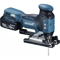
| Product type | Cordless jigsaw |
| Brand | Makita |
| Model | 4334D |
| Stroke length | 26 mm |
| Maximum cutting capacity (wood) | 135 mm |
| Maximum cutting capacity (mild steel) | 10 mm |
| Maximum cutting capacity (aluminum) | 20 mm |
| Variable speed | 500 - 2800 strokes/min (adjustable to 5 positions) |
| Orbital action | Yes, 4 positions (0 to III) |
| Power source | 18 V Ni-MH battery |
| Charger | Model DC1801 (rapid charger) |
| Net weight | 3.3 kg |
| Total length | 281 mm |
| Anti-split device | Yes, removable |
| Plastic base plate | Optional (protects delicate surfaces) |
| Rip guide | Optional (for straight cuts up to 150 mm) |
| Circle guide | Optional (radius up to 200 mm) |
| Dust extraction nozzle | Optional (connection to a Makita vacuum cleaner) |
| Bevel cut | Yes, from 0° to 45° (left and right) |
| Plunge cut | Possible (method B without starter hole) |
| Light | No (not mentioned) |
| Safety | Safety button (prevents accidental starts) |
| Maintenance | Cleaning the blade holder fixture; replacement of carbon brushes |
| Noise level | Pressure: 85 dB(A); Power: 98 dB(A) |
| Vibration | Weighted acceleration: 6 m/s² |
Frequently Asked Questions - 4334D MAKITA
User questions about 4334D MAKITA
0 question about this device. Answer the ones you know or ask your own.
Ask a new question about this device
Download the instructions for your Electric saw in PDF format for free! Find your manual 4334D - MAKITA and take your electronic device back in hand. On this page are published all the documents necessary for the use of your device. 4334D by MAKITA.
USER MANUAL 4334D MAKITA
Explanation of general view
1 Button
2 Battery cartridge
3 Charging light
4 Lever
5 Lock-off button
6 Switch trigger
7 Speed adjusting dial
8 Base
9 Anti-splintering device
10 Screw
11 Plastic base plate
12 Hex wrench
13 Bolt
14 Guide rule
15 Threaded knob
16 Circular guide
17 Pin
18 Vacuum head
19 Blade installing lever
20 Blade holder
21 Clamp
22 Roller
23 Slot
24 Blade
25 Hold blade against blade holder
26 Cutting line
27 Base securing lever
28 Dent mark
29 Slot
30 Graduations
31 Limit mark
32 Screwdriver
33 Brush holder cap
SPECIFICATIONS
Model 4334D
Length of stroke 26 mm
Max. cutting capacities
Wood 135 mm
Mild steel 10 mm
Aluminum 20 mm
Strokes per minute 500-2,800
Overall length 281 mm
Net weight 3.3 kg
Rated voltage D.C. 18 V
- Due to our continuing program of research and development, the specifications herein are subject to change without notice.
Note: Specifications may differ from country to country.
Safety hints
For your own safety, please refer to the enclosed safety instructions.
IMPORTANT SAFETY INSTRUCTIONS
FOR CHARGER & BATTERY
ENC001-3
- SAVE THESE INSTRUCTIONS - This manual contains important safety and operating instructions for battery charger.
- Before using battery charger, read all instructions and cautionary markings on (1) battery charger, (2) battery, and (3) product using battery.
- CAUTION - To reduce risk of injury, charge only MAKITA type rechargeable batteries. Other types of batteries may burst causing personal injury and damage.
- Do not expose charger to rain or snow.
- Use of an attachment not recommended or 3. sold by the battery charger manufacturer may result in a risk of fire, electric shock, or injury to persons.
- To reduce risk of damage to electric plug and cord, pull by plug rather than cord when disconnecting charger.
-
Make sure cord is located so that it will not be stepped on, tripped over, or otherwise subjected to damage or stress.
-
Do not operate charger with damaged cord or plug - replace them immediately.
- Do not operate charger if it has received a sharp blow, been dropped, or otherwise damaged in any way; take it to a qualified serviceman.
- Do not disassemble charger or battery cartridge; take it to a qualified serviceman when service or repair is required. Incorrect reassembly may result in a risk of electric shock or fire.
- To reduce risk of electric shock, unplug charger from outlet before attempting any maintenance or cleaning. Turning off controls will not reduce this risk.
- The battery charger is not intended for use by young children or infirm persons without supervision.
- Young children should be supervised to ensure that they do not play with the battery charger.
- If operating time has become excessively shorter, stop operating immediately. It may result in a risk of overheating, possible burns and even an explosion.
- If electrolyte gets into your eyes, rinse them out with clear water and seek medical attention right away. It may result in loss of your eyesight.
ADDITIONAL SAFETY RULES FOR CHARGER & BATTERY CARTRIDGE
- Do not charge battery cartridge when temperature is BELOW 10^ (50^) or ABOVE 40^ (104^) .
- Do not attempt to use a step-up transformer, an engine generator or DC power receptacle. 3. Do not allow anything to cover or clog the charger vents.
Always cover the battery terminals with the battery cover when the battery cartridge is not used.
- Do not short the battery cartridge:
(1) Do not touch the terminals with any conductive material.
(2) Avoid storing battery cartridge in a container with other metal objects such as nails, coins, etc.
(3) Do not expose battery cartridge to water rain.
A battery short can cause a large current flow, overheating, possible burns and even a break down.
- Do not store the tool and battery cartridge in locations where the temperature may reach or exceed 50^ (122^) .
- Do not incinerate the battery cartridge even if it is severely damaged or is completely worn out. The battery cartridge can explode in a fire
- Be careful not to drop, shake or strike battery.
-
Do not charge inside a box or container of at kind. The battery must be placed in a well ventilated area during charging.
-
Check for the proper clearance beneath the workpiece before cutting so that the blade will not strike the floor, workbench, etc.
- Hold the tool firmly.
- Check the blade is not contacting the workpiece before the switch is turned on.
8r Keep hands away from moving parts. - Do not leave the tool running. Operate the tool now, only when hand-held.
- Always switch off and wait for the blade to come to a complete stop before removing the blade from the workpiece.
- Do not touch the blade or the workpiece immediately after operation; they may be extremely hot and could burn your skin.
SAVE THESE INSTRUCTIONS.
ADDITIONAL SAFETY RULES FOR TOOL
ENB030-1
Installing or removing battery cartridge (Fig. 1)
Always switch off the tool before insertion or removal of the battery cartridge.
- To remove the battery cartridge, withdraw it from the seat-tool while pressing the buttons on both sides of the seat cartridge.
- Be aware that this tool is always in an operating condition, because it does not have to be plugged into an electrical outlet.
- Hold tool by insulated gripping surfaces when performing an operation where the cutting too may contact hidden wiring. Contact with a "live" wire will make exposed metal parts of the tool "live" and shock the operator.
- Avoid cutting nails. Inspect for and remove all nails from the workpiece before operation.
- Do not cut hollow pipe.
- Do not cut oversize workpiece.
To insert the battery cartridge, align the tongue on the battery cartridge with the groove in the housing and slip it into place. Always insert it all the way until it locks in place with a little click. If not, it may accidentally fall out of the tool, causing injury to you or someone around you.
Do not use force when inserting the battery cartridge. If the cartridge does not slide in easily, it is not being inserted correctly.
Charging (Fig. 2)
Your new battery cartridge is not charged. You will need to charge it before use. Use the battery charger Mo DC1801 to charge the battery cartridge.
Plug the battery charger into the proper A/C voltage source. The charging light will flash in green color. Insert the battery cartridge so that the plus and minus terminals on the battery cartridge are on the same sides as respective markings on the battery charger. Insert the cartridge fully into the port so that it rests on the charge port floor. When the battery cartridge is inserted, the charging light color will change from green to red and charging will begin. The charging light will remain lit steadily during charging. When the charging light color changes from red to green, the charging cycle is complete.
If you leave the battery cartridge in the charger after the charging cycle is complete, the charger will switch in its "trickle charge (maintenance charge)" mode which will last approximately 24 hours. After charging, unplug the charger from the power source. Refer to the table below for the charging time.
| Battery type | city (mAh) | Number of cells | Charging time |
| 1822 | 2,000 | 15 | Approx. 60 min. |
| 1833 | 2,200 | 15 | Approx. 65 min. |
| 1834 | 2,600 | 15 | Approx. 75 min. |
| 1835 | 3,000 | 15 | Approx. 90 min. |
CAUTION:
The battery charger Model DC1801 is for charging Makita battery cartridge. Never use it for other purposes or for other manufacturer's batteries.
- When you charge a new battery cartridge or a battery cartridge which has not been used for a long period time, it may not accept a full charge. This is a normal condition and does not indicate a problem. Your recharge the battery cartridge fully after discharging it completely and recharging a couple of times.
- If you charge a battery cartridge from a just-operated tool or a battery cartridge which has been left in a location exposed to direct sunlight or heat for a long time, the charging light may flash in red color. If you occurs, wait for a while. Charging will begin after the battery cartridge cools. The battery cartridge will cool faster if you remove the battery cartridge from the battery charger.
- If the charging light flashes alternately in green and red color, a problem exists and charging is not possible. The terminals on the charger or battery cartridge are clogged with dust or the battery cartridge is worn by the damaged.
Trickle charge (Maintenance charge)
If you leave the battery cartridge in the charger to prevent spontaneous discharging after full charge, the charger will switch into its "trickle charge (maintenance charge)" mode and keep the battery cartridge fresh fully charged.
Tips for maintaining maximum battery life
- Charge the battery cartridge before completely discharged.
Always stop tool operation and charge the battery cartridge when you notice less tool power. - Never recharge a fully charged battery cartridge.
Overcharging shortens the battery service life. - Charge the battery cartridge with room temperature at 10^ - 40^ (50^ - 104^)
Let a hot battery cartridge cool down before charging it. - Charge the Nickel Metal Hydride battery cartridge when you do not use it for more than six months.
Selecting the cutting action (Fig. 3)
This tool can be operated with an orbital or a straight line cutting action.
To change the cutting action, just turn the lever to the desired cutting action position. Refer to the table to help determine the appropriate cutting action.
| Position C | Cutting action Applications | |
| O | Straight line cutting action For cutting mild steel, stainless steel and plastics. For clean cuts in wood and plywood. | |
| I Small | orbit cutting action For cutting mild steel, aluminum and hard wood. | |
| II | Medium orbit cutting action For cutting wood and plywood. For fast cutting in aluminum and mild steel. | |
| III | Large orbit cutting action For fast cutting in wood and plywood. | |
Switch action (Fig. 4)
CAUTION:
Before inserting the battery cartridge into the tool, it always check to see that the switch trigger actually properly and returns to the "OFF" position when released.
- To prevent the switch trigger from being accidentally pulled, a lock-off button is provided. To start the depress the lock-off button and pull the switch to Release the switch trigger to stop.
Speed adjusting dial (Fig. 5)
The tool speed can be adjusted and maintained between 500 and 2,800 strokes per minute by turning the adjusting dial. The dial is marked 1 (lowest speed to 5 (full speed).
Refer to the table below to select the proper speed for the workpiece to be cut. However, the appropriate speed may differ with the type or thickness of the workpiece. In general, higher speeds will allow you to get workpieces faster but the service life of the blade will be reduced.
| Workpiece to be cut | Number on adjusting dial |
| Wood 3 - 5 | |
| Mild steel 3 - 5 | |
| Stainless steel 3 - | 4 |
| Aluminum 2 - 3 | |
| Plastics 1 - 4 |
CAUTION:
Adjust the speed adjusting dial only within the range of numbers 1 through 5. Do not force the dial beyond this range or damage to the tool may result.
Anti-splintering device (Fig. 6)
To reduce the potential for workpiece surface splintering, the anti-splintering device can be used. Fit it into the base from below so that it surrounds the side of the blade.
Plastic base plate (optional accessory)
(Fig. 7)
Use the plastic base plate when cutting decorative veneers, plastics, etc. It protects sensitive or delicate surfaces from damage. To replace the base plate, 4. remove the four screws.
Guide rule (rip fence; optional accessory)
(Fig. 8)
When cutting widths of under 150~mm repeatedly, use of the guide rule will assure fast, clean, straight cuts. To install it, loosen the bolt on the front of the base. Slip in the guide rule and secure the bolt.
Circular guide (optional accessory) (Fig. 9)
Use of the circular guide insures clean, smooth Re cutting of circles (radius: under 200~mm .Insert the1. pin through the center hole and secure it with the threaded knob. Move the base of the tool forward 2. fully. Then install the circular guide on the base in the same manner as the guide rule.
Vacuum head (optional accessory)
(Fig. 10 & 11)
The vacuum head is recommended to perform cleaning operations. Install the plastic cover on the tool by fitting it into the notches in the tool. 5.
To attach the vacuum head on the tool, insert the h of the vacuum head into the hole in the base. The vacuum head can be installed on either left or right side of the base. Then connect a Makita vacuum cleaner to the vacuum head.
Installing or removing the saw blade
CAUTION:
- Always be sure that the tool is switched off and the battery cartridge is removed before installing or removing the blade.
- Always clean off the blade and blade holder before installing the blade. Chips or foreign matter on them may cause insufficient securing of the blade, possibly resulting in blade breakage or serious injury.
Installation
1.1. Push the blade installing lever in the (1) direction to release it. (Fig. 12)
Pull the blade installing lever in the (2) direction until it stops with a little click. If you have difficulty pulling it out, try to do so while moving it back and forth in the (3) direction.
Rotate the blade installing lever in the (4) direction until the clamp protrudes 5 - 7mm from the blade holder. (Fig. 13)
CAUTION:
If you rotate the blade installing lever excessively, the clamp will also rotate and finally come off. In this case, re-install it properly as lately described in "Installing clamp".
With the blade teeth facing forward, insert the blade into the blade holder as far as it will go. Make sure that the back edge of the blade fits properly into the groove of the roller. (Fig. 14)
- With the blade held against the blade holder, pause to rotate the blade installing lever in the (5) direction. Stops until it stops. (Fig. 15)
With the blade installing lever held in this position, push it in the (6) direction. Then rotate the blade installing lever to its original position. (Fig. 16)
Removal
e1. Push the blade installing lever in the (1) direction to release it. (Fig. 17)
2. Pull the blade installing lever in the (2) direction the until it stops with a little click. If you have difficulty pulling it out, try to do so while moving it back and forth in the (3) direction.
3. Rotate the blade installing lever in the (4) direction and remove the blade. (Fig. 18)
-
Rotate the blade installing lever in the (5) direction until it stops. (Fig. 19)
-
With the blade installing lever held in this position, a hockush it in the (6) direction. Then rotate the blade installing lever to its original position. (Fig. 20)
OPERATION
Cutting operation
CAUTION:
- Always hold the tool with the base flush with the workpiece. Failure to do so may cause a slanted cutting surface and blade breakage.
- Advance the tool very slowly when cutting curves scrolling. Forcing the tool may cause a slanted cutting surface and blade breakage.
Finishing edges (Fig. 27)
To trim edges or make slight dimensional adjustments, run the blade lightly along the cut edges.
Metal cutting
Always use a suitable coolant (cutting oil) when cutting metal. Failure to do so will cause significant blade wear. The underside of the workpiece can be greased instead of using a coolant.
Turn the tool on without the blade making any conmbaintenance
Rest the base flat on the workpiece and gently move the tool forward along the previously marked cutting CAUTION:
the tool forward along the previously marked cutting line. (Fig. 21) Always be sure that the tool is switched off and the battery cartridge is removed before carrying out any
Bevel cutting (Fig. 22 & 23)
CAUTION:
Always remove the battery from the tool before making any adjustments.
With the base tilted, you can make bevel cuts at an angle the blade holder.
angle between 0^ and 45^ (left or right). Loosen the base securing lever and move the base so that the
dent mark in the motor housing is aligned with the push the blade installing lever in the (1) direction in the base. Tilt the base until the desired bevel angle to release it. (Fig. 28)
is obtained. The edge of the motor housing indicates the bevel angle by graduations. The tighten the base securing lever to secure the base.
NOTE:
Always remove the plastic cover (chip shield) from tool when you make bevel cuts using an optional guide rule (rip fence) or circular guide.
Flush cutting (Fig. 24)
Loosen th base securing lever and slide the base all the way back. Then tighten the base securing lever to secure the base. 1.
Cutouts (Fig. 25 & 26)
Cutouts can be made with either of two methods A B.
A) Boring a starting hole: For internal cutouts without a lead-in cut from a edge, pre-drill a starting hole more than 12mm diameter. Insert the blade into this hole and hold the tool firmly against the workpiece to start your cut.
B) Plunge cutting:
You need not bore a starting hole or make a lead-in cut if you carefully do as follows.
- Tilt the tool up on the front edge of the base with the blade point positioned just above the workpiece surface.
- Apply pressure to the tool so that the front edge of the base will not move when you switch on the tool and gently lower the back end of the tool slowly.
- As the blade slices into the workpiece, slowly lower the base of the tool down onto the workpiece surface.
- Complete the cut in the normal manner.
Cleaning clamp on blade holder
If chips or foreign matter get into the clamp on the blade holder, clean out the clamp after removing it
from the blade holder.
Removing clamp
-
Push the blade installing lever in the (1) direction. Angle to release it. (Fig. 28)
-
Pull the blade installing lever in the (2) direction, use until it stops with a little click. If you have difficulty pulling it out, try to do so while moving it back and forth in the (3) direction.
The Rotate the blade installing lever in the (4) direction until it stops. The clamp will protrude from the blade holder. (Fig. 29 & 30) - Remove the clamp from the blade holder while rotating the clamp in the (5) direction. (Fig. 31)
Tlstalling clamp
-
Make sure that the blade installing lever has been rotated in the (4) direction until it stops. (Fig. 32)
-
Insert the clamp into the blade holder while rotating it in the (6) direction one quarter to one full to so that its slot will face forward. (Fig. 33)
CAUTION:
in Do not rotate the clamp more than one full turn when inserting in into the blade holder. If you do so, the blade may not be tightened firmly.
3. Grasp the clamp with your fingers so that it will not turn, then rotate the blade installing lever in the (7) direction until it stops. The clamp will go in the blade holder. (Fig. 34)
Replacing carbon brushes (Fig. 35 & 36)
Remove and check the carbon brushes regularly. Replace when they wear down to the limit mark. Keep the carbon brushes clean and free to slip in the holders. Both carbon brushes should be replaced at the same time. Use only identical carbon brushes.
Use a screwdriver to remove the brush holder caps. Take out the worn carbon brushes, insert the new ones and secure the brush holder caps.
To maintain product safety and reliability, repairs, maintenance or adjustment should be carried out by a Makita Authorized Service Center.
FRANÇAIS
Descriptif
1 Bouton
12 Clé hexagonale
24 Lame
2 Batterie
13 Boulon
Nominate spanning D.C. 18 V
VEILIGHEIDSVOORSCHRIFTEN VOOR ACCULADER EN ACCU
These accessories or attachments are recommended for use with your Makita tool specified in this manual. Use of any other accessories or attachments might present a risk of injury to persons. The accessories or attachments should be used only in the proper and intended manner.
F ACCESSOIRES
ATTENTION :
EC-DECLARATION OF CONFORMITY
The undersigned, Yasuhiko Kanzaki, authorized by Makita Corporation of America, 2650 Buford Highway, Buford, GA30518 declares that this product
(Serial No.: series production) manufactured by Makita Corporation of America in U.S.A is in compliance with the following standards standardized documents,
EN50260, EN55014,
in accordance with Council Directives, 89/336/EEC and 98/37/EC.
ITALIANO
Michigan Drive, Tongwell, Milton Keynes,
Bucks MK15 8JD, ENGLAND
PORTUGUES
de accordo com as directivas 89/336/CEE e 98/37/CE do Conselho.
NORSK
EUs SAMSVARS-ERKLÄERING
EU-DEKLARATION OM KONFORMITET
- Undertegnede, Yasuhiko Kanzaki, med fuldmagt fra 2. Makita Corporation of America, 2650 Buford Highway
Buford, GA30518, erklærhermed, at dette produit (Lobenummer:serieproduktion)
fremstillet at Makita Corporation of America in U.S.A.almistanut Makita Corporation of America in U.S.A er i overensstemmelse med de folgende standarder vastaa seuraavia standardeja tai stardadoituja asia-eller normsættende dokumenter, kirjoja
EN50260, EN55014
i overensstemmelse med Radets Direktiver 89/336/EEC og 98/37/EC.
SUOMI
VAKUUTUS EC-VASTAAVUDESTA
(AuXwAp: npaywyn oεipac)
Katakeuaevo ano Tnv Makita Corporation of America in U.S.A, Bpioketai oeuwvia e ta akoloutheta npotuna n tuonoineva yypapa,
EN50260, EN55014
Michigan Drive, Tongwell, Milton Keynes,
Bucks MK15 8JD, ENGLAND
ENGLISH
EC-DECLARATION OF CONFORMITY
The undersigned, Yasuhiko Kanzaki, authorized by Kang Lung Tamura Electronics Co., Ltd. No. 4 Industry 1st Street, Ping Tung Industry District Chiao Nan Li, Ping Tung City, Taiwan declares that this battery charger (Serial No.: series production) manufactured by Kao Lung Tamura Electronics Co., Ltd. in Taiwan is in compliance with the following standards or standardized documents, EN60335, EN55014, EN61000* in accordance with Council Directives, 73/23/EEC and 89/336/EEC.
*from 1st Jan. 2001
FRANÇAISE
DECLARATION DE CONFORMITE CE
Michigan Drive, Tongwell, Milton Keynes, Bucks MK15 8JD, ENGLAND
PORTUGUES
EU-DEKLARATION OM KONFORMITET
Undertegnede, Yasuhiko Kanzaki, med fuldmagt fra
Kao Lung Tamura Electronics Co., Ltd. No. 4 Indu
1st Street, Ping Tung Industry District Chiao Nan L
Ping Tung City, Taiwan, erklærhermed, at dette
batteriopladeren
- Undertegnede, Yasuhiko Kanzaki, med fullmakt fra
- Kao Lung Tamura Electronics Co., Ltd. No. 4 Industry
- 1st Street, Ping Tung Industry District Chiao Nan Li,
- Ping Tung City, Taiwan bekrefter herved at dette
- batterilader
O unoypawv, Yasuhiko Kanzaki,
EouoiobotnuevoacnoTnv tvaepiaKao Lung
Jamura Electronics Co., Ltd. No. 4 Industry 1st
Street, Ping Tung Industry District Chiao Nan Li,
Ping Tung City, Taiwan, oovcio auto to
oprtiots maataipia
(AuEwAp: npaywyn eipac)
kaataokekuaoévo ano tny Etaipelia Kao Lung
Tamura Electronics Co., Ltd. 0tnv Taiwan, piokeTai oE ouuwovia e Ta aKoAouOa npotuna n tuonoineva eyypapa,
Michigan Drive, Tongwell, Milton Keynes,
Bucks MK15 8JD, ENGLAND
ENGLISH
Noise And Vibration Of Model 4334D
The typical A-weighted noise levels are
sound pressure level: 85 dB (A)
sound power level: 98 dB (A)
- Wear ear protection. -
The typical weighted root mean square acceleration value is 6 m/s
PORTUGUES
Ruido e Vibracao do Modelo 4334D
- Explanation of general view
- SPECIFICATIONS
- Model 4334D
- Safety hints
- IMPORTANT SAFETY INSTRUCTIONS
- FOR CHARGER & BATTERY
- ADDITIONAL SAFETY RULES FOR CHARGER & BATTERY CARTRIDGE
- ADDITIONAL SAFETY RULES FOR TOOL
- Installing or removing battery cartridge (Fig. 1)
- Charging (Fig. 2)
- CAUTION:
- Trickle charge (Maintenance charge)
- Tips for maintaining maximum battery life
- Selecting the cutting action (Fig. 3)
- Switch action (Fig. 4)
- Speed adjusting dial (Fig. 5)
- Anti-splintering device (Fig. 6)
- Plastic base plate (optional accessory)
- (Fig. 7)
- Guide rule (rip fence; optional accessory)
- (Fig. 8)
- Circular guide (optional accessory) (Fig. 9)
- Vacuum head (optional accessory)
- (Fig. 10 & 11)
- Installing or removing the saw blade
- Installation
- Removal
- OPERATION
- Cutting operation
- Finishing edges (Fig. 27)
- Metal cutting
- Bevel cutting (Fig. 22 & 23)
- NOTE:
- Flush cutting (Fig. 24)
- Cutouts (Fig. 25 & 26)
- Cleaning clamp on blade holder
- Removing clamp
- Tlstalling clamp
- Replacing carbon brushes (Fig. 35 & 36)
- FRANÇAIS
- Descriptif
- VEILIGHEIDSVOORSCHRIFTEN VOOR ACCULADER EN ACCU
- F ACCESSOIRES
- ATTENTION :
- EC-DECLARATION OF CONFORMITY
- ITALIANO
- PORTUGUES
- NORSK
- EUs SAMSVARS-ERKLÄERING
- EU-DEKLARATION OM KONFORMITET
- SUOMI
- VAKUUTUS EC-VASTAAVUDESTA
- ENGLISH
- FRANÇAISE
- DECLARATION DE CONFORMITE CE
- Noise And Vibration Of Model 4334D
- Ruido e Vibracao do Modelo 4334D
Brand : MAKITA
Model : 4334D
Category : Electric saw