
JV001G - Electric saw MAKITA - Free user manual and instructions
Find the device manual for free JV001G MAKITA in PDF.
| Product type | Cordless jigsaw |
| Brand | Makita |
| Model | JV001G |
| Stroke length | 26 mm |
| Strokes per minute | 800 - 3500 min⁻¹ |
| Blade type | Type B (universal) |
| Max cutting capacity (wood) | 135 mm |
| Max cutting capacity (mild steel) | 10 mm |
| Max cutting capacity (aluminum) | 20 mm |
| Rated voltage | 36 V - 40 V max. DC |
| Total length (with BL4025) | 283 mm |
| Net weight | 2.6 - 2.9 kg (depending on battery) |
| Compatible batteries | BL4020, BL4025, BL4040, BL4040F (Li-ion 36 V) |
| Compatible chargers | DC40RA, DC40RB, DC40RC, DC40WA |
| Cutting motion | Orbital (4 positions) and straight |
| Speed setting | 6-position dial |
| Electronic functions | Soft start, constant speed control, electric brake |
| Front light | LED with 3 brightness levels |
| Bevel cutting capacity | 0° to 45° (left and right) |
| Anti-splinter device | Yes, removable |
| Dust extraction port | Yes (optional accessory) |
| Parallel guide | Yes (optional accessory) |
| Storage hex wrench | Integrated |
| Sound pressure level | 90 dB(A) |
| Vibration level (wood) | 4.6 m/s² (K=2.5) |
| Vibration level (sheet metal) | 4.8 m/s² (K=1.5) |
| Protection systems | Overload, overheating, total discharge |
Frequently Asked Questions - JV001G MAKITA
User questions about JV001G MAKITA
0 question about this device. Answer the ones you know or ask your own.
Ask a new question about this device
Download the instructions for your Electric saw in PDF format for free! Find your manual JV001G - MAKITA and take your electronic device back in hand. On this page are published all the documents necessary for the use of your device. JV001G by MAKITA.
USER MANUAL JV001G MAKITA
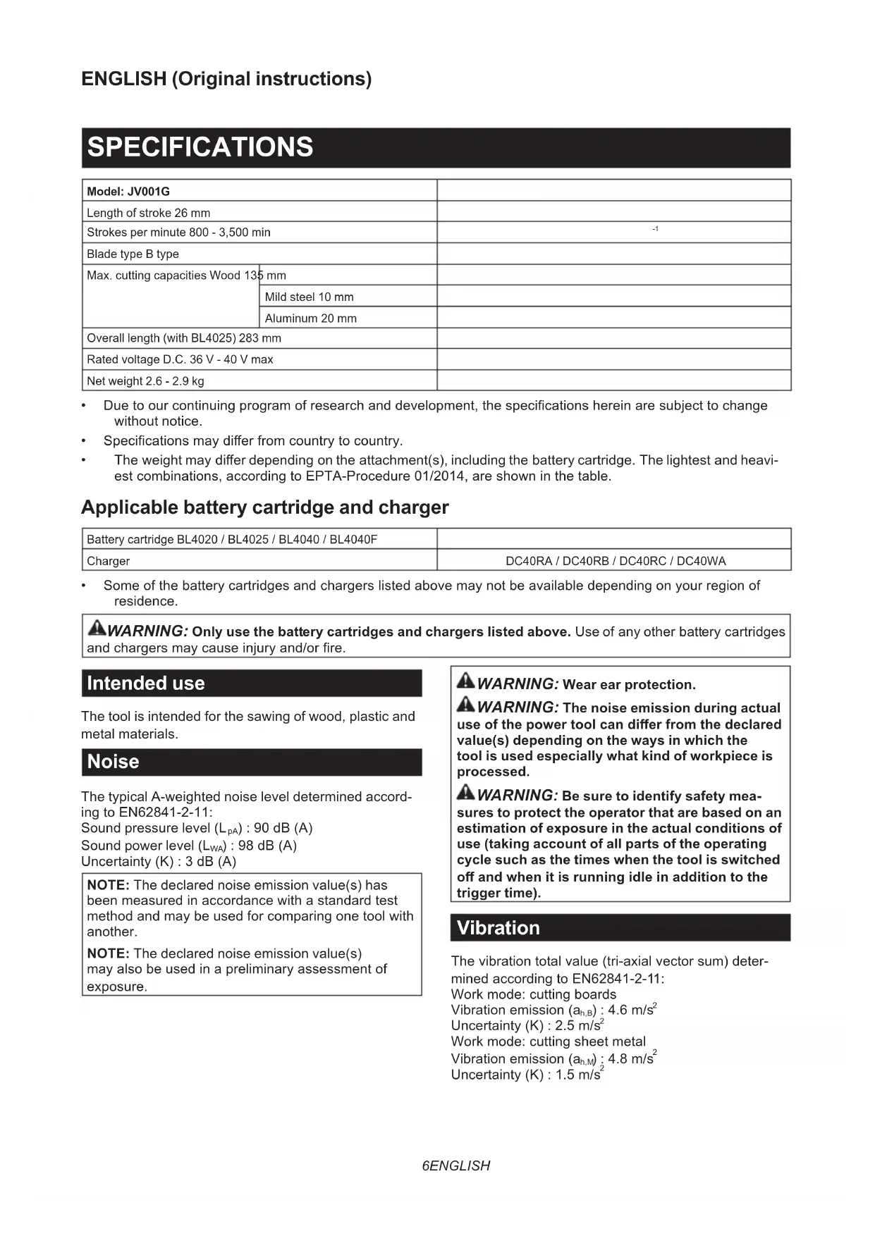
| SPECIFICATIONS | |
| Model: JV001G | |
| Length of stroke 26 mm | |
| Strokes per minute 800 - 3,500 min | -1 |
| Blade type B type | |
| Max. cutting capacities Wood 135 mm | |
| Mild steel 10 mm | |
| Aluminum 20 mm | |
| Overall length (with BL4025) 283 mm | |
| Rated voltage D.C. 36 V - 40 V max | |
| Net weight 2.6 - 2.9 kg | |
Due to our continuing program of research and development, the specifications herein are subject to change without notice.
- Specifications may differ from country to country.
The weight may differ depending on the attachment(s), including the battery cartridge. The lightest and heaviest combinations, according to EPTA-Procedure 01/2014, are shown in the table.
Applicable battery cartridge and charger
| Battery cartridge BL4020 / BL4025 / BL4040 / BL4040F | |
| Charger | DC40RA / DC40RB / DC40RC / DC40WA |
Some of the battery cartridges and chargers listed above may not be available depending on your region of residence.
WARNING: Only use the battery cartridges and chargers listed above. Use of any other battery cartridges and chargers may cause injury and/or fire.
Intended use
The tool is intended for the sawing of wood, plastic and metal materials.
Noise
The typical A-weighted noise level determined according to EN62841-2-11:
Sound pressure level (LpA):90 dB (A)
Sound power level (LWA):98 dB (A)
Uncertainty (K): 3 dB (A)
NOTE: The declared noise emission value(s) has been measured in accordance with a standard test method and may be used for comparing one tool with another.
NOTE: The declared noise emission value(s) may also be used in a preliminary assessment of exposure.
WARNING: Wear ear protection.
WARNING: The noise emission during actual use of the power tool can differ from the declared value(s) depending on the ways in which the tool is used especially what kind of workpiece is processed.
WARNING: Be sure to identify safety measures to protect the operator that are based on an estimation of exposure in the actual conditions of use (taking account of all parts of the operating cycle such as the times when the tool is switched off and when it is running idle in addition to the trigger time).
Vibration
The vibration total value (tri-axial vector sum) determined according to EN62841-2-11:
Work mode: cutting boards
Vibration emission (ah,B):4.6m / s2
Uncertainty (K): 2.5m / s2
Work mode: cutting sheet metal
Vibration emission (ah,M):4.8m / s2
Uncertainty (K): 1.5m / s2
NOTE: The declared vibration total value(s) has been measured in accordance with a standard test method and may be used for comparing one tool with another.
NOTE: The declared vibration total value(s) may also be used in a preliminary assessment of exposure.
WARNING: The vibration emission during actual use of the power tool can differ from the declared value(s) depending on the ways in which the tool is used especially what kind of workpiece is processed.
WARNING: Be sure to identify safety measures to protect the operator that are based on an estimation of exposure in the actual conditions of use (taking account of all parts of the operating cycle such as the times when the tool is switched off and when it is running idle in addition to the trigger time).
Declarations of Conformity
For European countries only
The Declarations of conformity are included in Annex A to this instruction manual.
SAFETYWARNINGS
General power tool safety warnings
WARNING Read all safety warnings, instructions, illustrations and specifications provided with this power tool. Failure to follow all instructions listed below may result in electric shock, fire and/or serious injury.
Save all warnings and instructions for future reference.
The term "power tool" in the warnings refers to your mains-operated (corded) power tool or battery-operated (cordless) power tool.
Cordless jig saw safety warnings
- Hold the power tool by insulated gripping surfaces, when performing an operation where the cutting accessory may contact hidden wiring. Cutting accessory contacting a "live" wire may make exposed metal parts of the power tool "live" and could give the operator an electric shock.
- Use clamps or another practical way to secure and support the workpiece to a stable platform. Holding the workpiece by hand or against your body leaves it unstable and may lead to loss of control.
- Always use safety glasses or goggles. Ordinary eye or sun glasses are NOT safety glasses.
- Avoid cutting nails. Inspect workpiece for any nails and remove them before operation.
- Do not cut oversize workpiece.
- Check for the proper clearance around the
workpiece before cutting so that the jig saw blade will not strike the floor, workbench, etc.
- Hold the tool firmly.
- Make sure the jig saw blade is not contacting the workpiece before the switch is turned on.
- Keep hands away from moving parts.
- Do not leave the tool running. Operate the tool only when hand-held.
- Always switch off and wait for the jig saw blade to come to a complete stop before removing the jig saw blade from the workpiece.
- Do not touch the jig saw blade or the workpiece immediately after operation; they may be extremely hot and could burn your skin.
- Do not operate the tool at no-load unnecessarily.
- Some material contains chemicals which may be toxic. Take caution to prevent dust inhalation and skin contact. Follow material supplier safety data.
- Always use the correct dust mask/respirator for the material and application you are working with.
SAVE THESE INSTRUCTIONS.
WARNING: DO NOT let comfort or familiarity with product (gained from repeated use) replace strict adherence to safety rules for the subject product. MISUSE or failure to follow the safety rules stated in this instruction manual may cause serious personal injury.
Important safety instructions for battery cartridge
- Before using battery cartridge, read all instructions and cautionary markings on (1) battery charger, (2) battery, and (3) product using battery.
- Do not disassemble or tamper with the battery cartridge. It may result in a fire, excessive heat, or explosion.
- If operating time has become excessively shorter, stop operating immediately. It may result in a risk of overheating, possible burns and even an explosion.
- If electrolyte gets into your eyes, rinse them out with clear water and seek medical attention right away. It may result in loss of your eyesight.
- Do not short the battery cartridge:
(1) Do not touch the terminals with any conductive material.
(2) Avoid storing battery cartridge in a container with other metal objects such as nails, coins, etc.
(3) Do not expose battery cartridge to water or rain. A battery short can cause a large current flow, overheating, possible burns and even a breakdown.
- Do not store and use the tool and battery cartridge in locations where the temperature may
reach or exceed 50ircC (122ircF)
- Do not incinerate the battery cartridge even if it is severely damaged or is completely worn out. The battery cartridge can explode in a fire.
- Do not nail, cut, crush, throw, drop the battery cartridge, or hit against a hard object to the battery cartridge. Such conduct may result in a fire, excessive heat, or explosion.
- Do not use a damaged battery.
- The contained lithium-ion batteries are subject to the Dangerous Goods Legislation requirements.
For commercial transports e.g. by third parties, forwarding agents, special requirement on packaging and labeling must be observed.
For preparation of the item being shipped, consulting an expert for hazardous material is required. Please also observe possibly more detailed national regulations.
Tape or mask off open contacts and pack up the battery in such a manner that it cannot move around in the packaging.
- When disposing the battery cartridge, remove it from the tool and dispose of it in a safe place. Follow your local regulations relating to disposal of battery.
- Use the batteries only with the products specified by Makita. Installing the batteries to non-compliant products may result in a fire, excessive heat, explosion, or leak of electrolyte.
- If the tool is not used for a long period of time, the battery must be removed from the tool.
- During and after use, the battery cartridge may take on heat which can cause burns or low temperature burns. Pay attention to the handling of hot battery cartridges.
- Do not touch the terminal of the tool immediately after use as it may get hot enough to cause burns.
- Do not allow chips, dust, or soil stuck into the terminals, holes, and grooves of the battery cartridge. It may cause heating, catching fire, burst and malfunction of the tool or battery cartridge, resulting in burns or personal injury.
- Unless the tool supports the use near high-voltage electrical power lines, do not use the battery cartridge near high-voltage electrical power lines. It may result in a malfunction or breakdown of the tool or battery cartridge.
- Keep the battery away from children.
SAVE THESE INSTRUCTIONS.
CAUTION: Only use genuine Makita batteries.
Use of non-genuine Makita batteries, or batteries that have been altered, may result in the battery bursting causing fires, personal injury and damage. It will also void the Makita warranty for the Makita tool and charger.
Tips for maintaining maximum battery life
- Charge the battery cartridge before completely discharged. Always stop tool operation and charge the battery cartridge when you notice
less tool power.
- Never recharge a fully charged battery cartridge. Overcharging shortens the battery service life.
- Charge the battery cartridge with room temperature at 10ircC - 40ircC (50°F - 104°F). Let a hot battery cartridge cool down before charging it.
- When not using the battery cartridge, remove it from the tool or the charger.
- Charge the battery cartridge if you do not use it for a long period (more than six months).
FUNCTIONAL DESCRIPTION
CAUTION: Always be sure that the tool is switched off and the battery cartridge is removed before adjusting or checking function on the tool.
Installing or removing battery cartridge
CAUTION: Always switch off the tool before installing or removing of the battery cartridge.
CAUTION: Hold the tool and the battery cartridge firmly when installing or removing battery cartridge. Failure to hold the tool and the battery cartridge firmly may cause them to slip off your hands and result in damage to the tool and battery cartridge and a personal injury.
To install the battery cartridge, align the tongue on the battery cartridge with the groove in the housing and slip it into place. Insert it all the way until it locks in place with a little click. If you can see the red indicator as shown in the figure, it is not locked completely.
To remove the battery cartridge, slide it from the tool while sliding the button on the front of the cartridge.
Fig.1: 1. Red indicator 2. Button 3. Battery cartridge
CAUTION: Always install the battery cartridge fully until the red indicator cannot be seen. If not, it may accidentally fall out of the tool, causing injury to you or someone around you.
CAUTION: Do not install the battery cartridge forcibly. If the cartridge does not slide in easily, it is not being inserted correctly.
Indicating the remaining battery capacity
Press the check button on the battery cartridge to indicate the remaining battery capacity. The indicator lamps light up for a few seconds.
Fig.2: 1. Indicator lamps 2. Check button
| Indicator lamps Remaining | capacity | ||
| Lighted Off | Blinking | ||
| 75% to 100% | |||
| 50% to 75% | |||
| 25% to 50% | |||
| 0% to 25% | |||
| Charge the battery. | |||
| The battery may have malfunctioned. | |||
NOTE: Depending on the conditions of use and the ambient temperature, the indication may differ slightly from the actual capacity.
NOTE: The first (far left) indicator lamp will blink when the battery protection system works.
Tool / battery protection system
The tool is equipped with a tool/battery protection system. This system automatically cuts off power to the motor to extend tool and battery life. The tool will automatically stop during operation if the tool or battery is placed under one of the following conditions:
Overload protection
When the battery is operated in a manner that causes it to draw an abnormally high current, the tool automatically stops without any indication. In this situation, turn the tool off and stop the application that caused the tool to become overloaded. Then turn the tool on to restart.
Overheat protection
When the tool or battery is overheated, the tool stops automatically and the lamp blinks. In this case, let the tool and battery cool before turning the tool on again.
Overdischarge protection
When the battery capacity is not enough, the tool stops automatically. In this case, remove the battery from the tool and charge the battery.
Protections against other causes
Protection system is also designed for other causes that could damage the tool and allows the tool to stop automatically. Take all the following steps to clear the causes, when the tool has been brought to a temporary halt or stop in operation.
- Turn the tool off, and then turn it on again to restart.
- Charge the battery(ies) or replace it/them with recharged battery(ies).
- Let the tool and battery(ies) cool down.
If no improvement can be found by restoring protection system, then contact your local Makita Service Center.
Selecting the cutting action
This tool can be operated with an orbital or a straight line (up and down) cutting action. The orbital cutting action thrusts the jig saw blade forward and increases cutting speed.
Fig.3: 1. Cutting action changing lever
To change the cutting action, turn the cutting action changing lever to the desired cutting action position. Refer to the table to select the appropriate cutting action.
| Position Cutting action Applications | |
| 0 Straight line cutting action | For cutting mild steel, stainless steel and plastics. |
| For clean cuts in wood and plywood. | |
| I Small orbital cutting action | For cutting mild steel, aluminum and hard wood. |
| II Medium orbital cutting action | For cutting wood and plywood. |
| For fast cutting in aluminum and mild steel. | |
| III Large orbital cutting action | For fast cutting in wood and plywood. |
Lighting up the front lamp
CAUTION: Do not look in the light or see the source of light directly.
Press the lock switch to turn on the lamp. Press the lock switch again to turn off the lamp.
Fig.4: 1. Lock switch 2. Lamp
The brightness has three levels. To change the brightness of the lamp, press and hold the lock switch when turning on the lamp. About 1 second after pressing and holding the lock switch, the brightness of the lamp will start to decrease. The brightness returns to the highest level from the lowest level and repeats the decrease. Release the lock switch when you reach the desired brightness. It turns the tool into standby mode, too.
NOTICE: When the tool is overheated, the lamp blinks. Cool down the tool fully before operating the tool again.
NOTE: Press and hold the lock switch continuously to cycle through the three brightness levels.
NOTE: The brightness of the lamp cannot be adjusted while the tool is in standby mode. To adjust the brightness, turn the tool off and then on again.
NOTE: The lamp lights up at the same brightness level as the last time the tool was used.
NOTE: Use a dry cloth to wipe the dirt off the lens of the lamp. Be careful not to scratch the lens of lamp, or it may lower the illumination.
Switch action
To turn on the tool, press the lock switch. The tool turns into the standby mode. To start the tool, press the ON/ standby switch in the standby mode. To stop the tool, press the ON/standby switch again. The tool turns into the standby mode. To turn off the tool, press the lock switch in the standby mode.
Fig.5: 1. Lock switch 2. ON/standby switch
NOTE: If the tool is left for 10 seconds without any operation in the standby mode, the tool automatically turns off and the lamp goes off.
NOTE: You can also stop and turn off the tool by pressing the lock switch while the tool is operating.
Speed adjusting dial
Fig.6: 1. Speed adjusting dial
The tool speed can be adjusted by turning the speed adjusting dial. You can get the highest speed at 6 and the lowest speed at 1.
Refer to the table to select the proper speed for the workpiece to be cut. However, the appropriate speed may differ with the type or thickness of the workpiece. In general, higher speeds will allow you to cut workpieces faster but the service life of the jig saw blade will be reduced.
| Workpiece Number | |
| Wood 4 - 6 | |
| Mild steel 3 - 6 | |
| Stainless steel 3 - 4 | |
| Aluminum 3 - 6 | |
| Plastics 1 - 4 |
NOTICE: The speed adjusting dial can be turned only as far as 6 and back to 1. Do not force it past 6 or 1, or the speed adjusting function may no longer work.
Electronic function
The tool is equipped with the electronic functions for easy operation.
Soft start
The soft-start function minimizes start-up shock, and makes the tool start smoothly.
Constant speed control
Electronic speed control for obtaining constant speed. Possible to get fine finish, because the rotating speed is kept constant even under load condition.
Soft no-load rotation
When the speed adjusting dial is set to "3" or higher, the tool automatically reduces the speed at no-load to reduce the vibration and align the jig saw blade with the cutting line easily. Once the tool starts cutting the workpiece, the tool speed increase and reach the preset speed.
NOTE: When the temperature is low, this function may not be available. This function also may not be available depending on the type of the material.
NOTE: If the speed does not decrease after cutting the workpiece, turn off the tool and then turn on it again.
Disabling or enabling the soft no-load rotation function
To disable or enable the soft no-load rotation function, follow the steps below.
- Make sure that the tool is turned off.
- Set the speed adjusting dial to "1".
- Press the lock switch to turn on the tool.
- Turn the speed adjusting dial to "6", and then set it back to "1".
The lamp blinks twice when the soft no-load rotation function is disabled or enabled. To enable or disable this function again, perform the same procedure again.
NOTE: If the soft no-load rotation function is disabled, the lamp blinks twice when the tool is turned on.
NOTE: You can also disable or enable the soft no-load rotation function by changing the speed adjusting dial to "6" - "1" - "6".
Electric brake
This tool is equipped with an electric brake. If the tool consistently fails to quickly stop after the switch trigger is released, have the tool serviced at a Makita service center.
ASSEMBLY
CAUTION: Always be sure that the tool is switched off and the battery cartridge is removed before carrying out any work on the tool.
Installing or removing jig saw blade
CAUTION: Always clean out all chips or foreign matter adhering to the jig saw blade and/or blade holder. Failure to do so may cause insufficient tightening of the jig saw blade, resulting in a serious personal injury.
CAUTION: Do not touch the jig saw blade or the workpiece immediately after operation. They may be extremely hot and could burn your skin.
CAUTION: Always secure the jig saw blade firmly. Insufficient tightening of the jig saw blade may cause the blade breakage or serious personal injury.
CAUTION: When you remove the jig saw blade, be careful not to hurt your fingers with the top of the jig saw blade or the tips of workpiece.
Before installing the jig saw blade, make sure that the jig saw blade clamp lever is in the released position.
To install the jig saw blade, insert the jig saw blade
(teeth facing forward) into the jig saw blade holder until it latches. The jig saw blade clamp lever moves to the fixed position by itself and the jig saw blade is locked. Make sure that the back edge of the jig saw blade fits into the roller. Pull the jig saw blade lightly to make sure that the jig saw blade does not fall off during operation.
Fig.7: 1. Jig saw blade clamp lever (fixed position) 2. Jig saw blade clamp lever (released position)
▶ Fig.8: 1. Jig saw blade holder 2. Jig saw blade clamp lever (released position) 3. Jig saw blade 4. Roller
CAUTION: Do not open the tool opener excessively, or it may cause tool damage.
To remove the jig saw blade, open the tool opener forward as far as it will go. This allows the jig saw blade to be released.
Fig.9: 1. Jig saw blade holder 2. Tool opener 3. Jig saw blade
NOTE: In case that it is difficult to remove the jig saw blade:
Turn the cutting action changing lever to the position "III" and slightly switch on the tool several times so that the jig saw blade holder moves to the bottom.
Make sure the jig saw blade clamp lever is in the fixed position when switch on the tool.
Remove the battery cartridge from the tool before installing or removing the jig saw blade.
NOTE: Occasionally lubricate the roller.
Hex wrench storage
When not in use, store the hex wrench as shown in the figure to keep it from being lost.
Fig.10: 1. Base 2. Hex wrench
Cover plate
Use the cover plate when cutting decorative veneers, plastics, etc. It protects sensitive or delicate surfaces from damage. Fit it on the bottom of the tool base.
Fig.11: 1. Cover plate 2. Base
Anti-splintering device
CAUTION: The anti-splintering device cannot be used when making bevel cuts.
For splinter-free cuts, the anti-splintering device can be used. To install the anti-splintering device, move the tool base all the way forward and fit it from the bottom of tool base.
When you use the cover plate, install the anti-splintering device onto the cover plate.
Fig.12: 1. Base 2. Anti-splintering device
Dust extraction
Optional accessory
The dust nozzle is recommended to perform clean cutting operations.
To attach the dust nozzle on the tool, insert the hook of dust nozzle into the hole in the base.
Fig.13: 1. Dust nozzle 2. Base
To secure the dust nozzle, tighten the clamp screw at the front of the dust nozzle. The dust nozzle can be installed on either left or right side of the base.
Fig.14: 1. Clamp screw
Then connect a Makita vacuum cleaner to the dust nozzle.
Fig.15: 1. Dust nozzle 2. Hose for vacuum cleaner
OPERATION
CAUTION: Always hold the base flush with the workpiece. Failure to do so may cause jig saw blade breakage, resulting in a serious injury.
CAUTION: Advance the tool very slowly when cutting curves or scrolling. Forcing the tool may cause a slanted cutting surface and jig saw blade breakage.
Turn the tool on without the jig saw blade making any contact and wait until the jig saw blade attains full speed. Then rest the base flat on the workpiece and gently move the tool forward along the previously marked cutting line.
Fig.16: 1. Cutting line 2. Base
Bevel cutting
CAUTION: Always be sure that the tool is switched off and the battery cartridge is removed before tilting the base.
With the base tilted, you can make bevel cuts at any angle between 0irc and 45irc (left or right).
Fig.17
To tilt the base, loosen the bolt on the bottom of the base with the hex wrench. Move the base so that the bolt is positioned in the center of the bevel slot in the base.
▶ Fig.18: 1. Hex wrench 2. Bolt 3. Base
Tilt the base until the desired bevel angle is obtained. The V-notch of the gear housing indicates the bevel angle by graduations. Then tighten the bolt firmly to secure the base.
Fig.19: 1. Bevel slot 2. Base 3. Bolt 4. Graduations 5.V-notch 6.Gear housing
Front flush cuts
Loosen the bolt on the bottom of the base with the hex wrench and slide the base all the way back. Then tighten the bolt to secure the base.
Fig.20: 1. Hex wrench 2. Bolt 3. Base
Cutouts
Cutouts can be made with either of two methods: "Boring a starting hole" or "Plunge cutting".
Boring a starting hole
For internal cutouts without a lead-in cut from an edge, pre-drill a starting hole 12mm or more in diameter. Insert the jig saw blade into this hole to start your cut.
Fig.21
Plunge cutting
You need not bore a starting hole or make a lead-in cut if you carefully do as follows.
Fig.22
- Tilt the tool up on the front edge of the base with the jig saw blade point positioned just above the workpiece surface.
- Apply pressure to the tool so that the front edge of the base will not move when you switch on the tool and gently lower the back end of the tool slowly.
- As the jig saw blade pierces the workpiece, slowly lower the base of the tool down onto the workpiece surface.
- Complete the cut in the normal manner.
Finishing edges
To trim edges or make dimensional adjustments, run the jig saw blade lightly along the cut edges.
Fig.23
Metal cutting
Always use a suitable coolant (cutting oil) when cutting metal. Failure to do so will cause significant jig saw blade wear. The underside of the workpiece can be greased instead of using a coolant.
Rip fence
Optional accessory
CAUTION: Always be sure that the tool is switched off and the battery cartridge is removed before installing or removing accessories.
Straight cuts
When repeatedly cutting widths of 160 mm or less, use of the rip fence will assure fast, clean, straight cuts.
Fig.24: 1. Rip fence (Guide rule)
To install, insert the rip fence into the rectangular hole on the side of the base with the fence guide facing down. Slide the rip fence to the desired cutting width position, then tighten the bolt to secure it.
▶ Fig.25: 1. Hex wrench 2. Bolt 3. Fence guide 4. Rip fence (Guide rule)
Circular cuts
When cutting circles or arcs of 170mm or less in radius, install the rip fence as follows.
Fig.26: 1. Rip fence (Guide rule)
CAUTION: Do not touch the tip of the circular guide pin. The sharp tip of the circular guide pin can cause injury.
- Insert the rip fence into the rectangular hole on the side of the base with the fence guide facing up.
- Insert the circular guide pin through either of the two holes on the fence guide. Screw the threaded knob onto the circular guide pin to secure the circular guide pin.
▶ Fig.27: 1. Threaded knob 2. Fence guide 3. Rip fence (Guide rule) 4. Circular guide pin 5. Bolt
- Slide the rip fence to the desired cutting radius, and tighten the bolt to secure it in place.
NOTE: Always use jig saw blades No. B-17, B-18, B-26 or B-27 when cutting circles or arcs.
Guide rail adapter set
Optional accessory
When cutting parallel and uniform width or cutting straight, the use of the guide rail and the guide rail adapter will assure the production of fast and clean cuts. To install the guide rail adapter, insert the rule bar into the square hole of the base as far as it goes. Secure the bolt with the hex wrench securely.
Fig.28: 1. Hex wrench 2. Rule bar 3. Bolt
Insert the rule bar into the square hole of the guide rail adapter, and secure the screw firmly. Place the guide rail adapter on the guide rail.
Fig.29: 1. Guide rail adapter 2. Guide rail 3. Screw
NOTICE: Always use jig saw blades No. B-8, B-13, B-16, B-17 or 58 when using the guide rail and the guide rail adapter.
MAINTENANCE
CAUTION: Always be sure that the tool is switched off and the battery cartridge is removed before attempting to perform inspection or maintenance.
NOTICE: Never use gasoline, benzine, thinner, alcohol or the like. Discoloration, deformation or cracks may result.
To maintain product SAFETY and RELIABILITY, repairs, any other maintenance or adjustment should be performed by Makita Authorized or Factory Service Centers, always using Makita replacement parts.
OPTIONAL ACCESSORIES
CAUTION: These accessories or attachments are recommended for use with your Makita tool specified in this manual. The use of any other accessories or attachments might present a risk of injury to persons. Only use accessory or attachment for its stated purpose.
If you need any assistance for more details regarding these accessories, ask your local Makita Service Center.
Jig saw blades
- Hex wrench 4
Rip fence (guide rule) set
- Guide rail adapter set
- Guide rail set
- Anti-splintering device
- Cover plate
- Dust nozzle assay
- Makita genuine battery and charger
NOTE: Some items in the list may be included in the tool package as standard accessories. They may differ from country to country.
SPÉCIFICATIONS
ACCESSIONS EN OPTION
WAARSCHUWING: Draag noorbescherming.

VEILIGHEIDSWAARSCHUWINGEN
OPTIONELE ACCESSOIRES
Móvo yia xwpe ts Eupwnns
Oi Anwoeicuupoppwan Tepiaaavovtai oTo Iapaptnma A oTo npov EYxepidio odnyiwv.
IPOEIAOIOIHSEIEA ΣΦΑΛΕΙΑΣ
Evikc npoeiooioeic a0aaleiayia to nEKTpiKO epyaeeio
A PPOEI OIOIH 1aIaOte oIc TIT PPOEI-0toinoeic aoPaeiaoc, odnyiec, EIKOVoypaoNoei KAI TPObiaypaec Tou npexovtaI e auto to nKtpiko epyaleio. H un tnpon oawv twv onyiw Tou avayapovtai katwetpw mTopei va kataanxi e nKtpoTTnGia, TUPKayia n/kai oobapo tpaumatio.
UαTe oεc TIG POeioToin-σεi KAI TIG OByie G YIA μελoVTIKn TApapouπn.
Tic TpoeioToinoei, o opoc «nEeKtpko epyaleio» avapepetai e nEeKtpko epyaleio Tou TpoopodTeiTai aTnv Kupia npoxn nEeKtpkou pEuμatoc (e nEeKtpko kaawio) n e nEeKtpko epyaleio Tou TpoopodTeiTai aTTOATAPIA (xwpiç nEeKtpko kaawio).
PpOeIbOMIOInoEic aOΦaλεiαç YIA TO φροŋtó πaIvδpouMko πpIoV
- Na kpatate to nAekptiko epyaleio aTIO TIG Movwpeves Etnipaveies AaBns OTAV kTealeite Epyaoiec katia TIG OTIOeS TO eApntma KOTnC mTopei va epthei OE tAnpHn ME KpumuVe
kaawbia. 2E TEPiTTWON ETTaPnC TOU EApTnA TOC KOTnC ME NkEeKtpoqopo Kaawio, MTOpeTa EKTEeIeV a MeTAAIAKc EApTnMaT a TONkTPIKOU Epyaleou va kataoTuV ta IIDA NkEeKtpoqopa KAI va TPOkAeOouv NkEeKtpoTAnxi OTo XeiPiOTn.
2. Na xpoiooiei oiyktnpec n kantoio aallo TpaKTIO eo yia va aoaaiiete kai va otnpiZETe to Teuaxio epyaoiaoc eia Otaepn PAtopua.Av Kpatate To TEuaxio epyaiaac e to xepi oac n ETTAVO tO Owaa c, 0a eivai aotaee Cai MTOpei va xaoteTov EEvyo.
3. Na xpoiooioite ravta yuaia aosaaicn TPOOTATEUTIKA yuaia. Ta ouvnOteva yuaia opaoewc n yuaia naiou DEN eivai yuaia aospaaieiac.
4. Na aTOpeUyETe TIV KOITIKAPIOW.Na EITI- 0ewpeITE TO TEuXIO EPYAOiAc YIA KAPPIA KAI aQaIPeOTe Ta TPIV aTIO Tn LEIToupyia.
5. Mny KoBETe UTepeyEeOn Teuaxia EpyaioaC.
6. Piv ao Tnv KOn, va eAeyxete oTI unapxei EapknC aoTaoyn yupw aoTO TEpaXIO epyaiaac wote n laa TnaiVbopouko TPOviou va m xTuTnoETo dTebo, Tov TAYKO epyaiaic, kTλ.
7. Kpatate To epyaaleio oTaepa.
8. Na βεβαινενεότε οή Αλαμα παλινδρομικου πριονιόν δεν αγγίζει το Εμαχίο εργασίας πριν ένν ευεργοποίησου τοῦ διακόπτη.
9. Mny nanoiae Ta xepia oac oe Kivoumu eva epn.
10. Mny aqnvete to epyaaleio avampevo. Na xepi- zoeTTo epyaaleio movo otav to kpatate oto XePI.
11. Na σβήνετε πάντα Τέργαλείο Kαιν περιμένετενα σταμαποδειν κινεῖται εντελως λάμα παλινόρουμικόν προνιόν πριν τη βγάζετε απότο τεμάχο εργασίας.
12. Mny ayyiTe Tn Ama Tn Aivdpouko Tpioviou n To Teuaxio Epyaoiasa eosw CetA Tn aeitoupvia.MTOpEi va eivai Egaepetikca 0eota kai va oas Tpokaedouv Ekaumata.
13. Mn ΘETETO epyaleio oE Aetoupyia xwpic qoptio otav auto dev eiva atapaintto.
14. Mepikauikau Tepiexouv xnukau Tou uTopoei va eivai toka. Na TPOOEXE wote va aTOpeuyETe TIV EIOVON OKOVNC KAI TIV EAnp n To δ µ .Na AkoLoutheite Ta δ δ ω ν aOaaleiac Tou TPOUNeut uIKOU.
15. Na xpooiotoiie TeavTa Tpoosnida KaTaNs OKovc/avantveuotnpa Tou evai KaTALnla Yia to uliko kai Tnv eapapoyi oC.
Eik.5: 1. Δiakottns KEAIDomega2. Δiakottns EVpyoioan/avaovns
IAPATHPHSEH: Av afoeTo epyaieio yia 10
EutepoaleTTa xwpic kaia aeitoupyia oTov tpotto
Aetoupyiac avauovn, to epyaieio aTVEpyoTOIEiTai
autouata kai n laumta oBnev.
- Applicable battery cartridge and charger
- Intended use
- Noise
- Vibration
- Declarations of Conformity
- For European countries only
- SAFETYWARNINGS
- General power tool safety warnings
- Save all warnings and instructions for future reference.
- Cordless jig saw safety warnings
- SAVE THESE INSTRUCTIONS.
- Important safety instructions for battery cartridge
- Tips for maintaining maximum battery life
- FUNCTIONAL DESCRIPTION
- Installing or removing battery cartridge
- Indicating the remaining battery capacity
- Tool / battery protection system
- Overload protection
- Overheat protection
- Overdischarge protection
- Protections against other causes
- Selecting the cutting action
- Lighting up the front lamp
- Switch action
- Speed adjusting dial
- Electronic function
- Soft start
- Constant speed control
- Soft no-load rotation
- Disabling or enabling the soft no-load rotation function
- Electric brake
- ASSEMBLY
- Installing or removing jig saw blade
- Hex wrench storage
- Cover plate
- Anti-splintering device
- Dust extraction
- Optional accessory
- OPERATION
- Bevel cutting
- Front flush cuts
- Cutouts
- Boring a starting hole
- Plunge cutting
- Finishing edges
- Metal cutting
- Rip fence
- Straight cuts
- Circular cuts
- Guide rail adapter set
- MAINTENANCE
- OPTIONAL ACCESSORIES
- ACCESSIONS EN OPTION
- VEILIGHEIDSWAARSCHUWINGEN
- OPTIONELE ACCESSOIRES
- IPOEIAOIOIHSEIEA ΣΦΑΛΕΙΑΣ
- Evikc npoeiooioeic a0aaleiayia to nEKTpiKO epyaeeio
- UαTe oεc TIG POeioToin-σεi KAI TIG OByie G YIA μελoVTIKn TApapouπn.
- PpOeIbOMIOInoEic aOΦaλεiαç YIA TO φροŋtó πaIvδpouMko πpIoV
Brand : MAKITA
Model : JV001G
Category : Electric saw