
HR2420 - Drill MAKITA - Free user manual and instructions
Find the device manual for free HR2420 MAKITA in PDF.
| Product type | Rotary hammer |
| Brand | Makita |
| Model | HR2420 |
| Drilling capacity in concrete | 24 mm |
| Drilling capacity in steel | 13 mm |
| Drilling capacity in wood | 32 mm |
| No load speed | 0 - 1,050 rpm |
| Blow rate | 0 - 4,900 bpm |
| Overall length | 432 mm |
| Net weight | 2.4 kg |
| Chuck type | SDS+ |
| Double insulation | Yes |
| Reversible rotation | Yes |
| Operating mode | Rotation only or rotation with hammering |
| Variable speed | Yes, by trigger |
| Adjustable side handle | Yes |
| Depth rod | Yes |
| Dust collector | Yes (for bits ≤ 14.5 mm) |
| Torque limiter | Yes |
| Sound pressure level | 90 dB(A) |
| Sound power level | 103 dB(A) |
| Weighted acceleration | 8 m/s² |
| Maintenance | Cleaning with blow bulb, regular greasing of the bit shank |
| Repairability | Entrust any repair to a Makita authorized service center |
| Supplied accessories | Side handle, depth rod, blow bulb, dust collector |
Frequently Asked Questions - HR2420 MAKITA
User questions about HR2420 MAKITA
0 question about this device. Answer the ones you know or ask your own.
Ask a new question about this device
Download the instructions for your Drill in PDF format for free! Find your manual HR2420 - MAKITA and take your electronic device back in hand. On this page are published all the documents necessary for the use of your device. HR2420 by MAKITA.
USER MANUAL HR2420 MAKITA
natural_image
Line drawing of a manual power tool with handle and screwdriver (no text or symbols)
text_image
Technical diagram of a mechanical device with numbered parts and rotational arrows indicating motion or assembly.1
text_image
Diagram showing a hand using a tool to apply material, labeled with parts 4 and 5.2
text_image
Diagram illustrating a mechanical assembly with labeled parts and directional arrows indicating motion or rotation.3
text_image
⑦4
text_image
Technical diagram of a cutting tool with numbered parts and directional arrow indicating motion5
text_image
A B c ⑪ ⑩6
text_image
Technical diagram of a mechanical or electrical component with labeled parts and directional arrows7

text_image
Diagram showing a hand holding a tool with an arrow and labeled point (13), indicating a step in a process.8
text_image
149
text_image
Technical diagram showing mechanical assembly with numbered parts and directional arrow indicating process flow10
text_image
Technical diagram showing mechanical assembly with numbered parts and directional arrow indicating motion11 12
text_image
Technical diagram of a mechanical component with labeled parts and dimension annotationSymbols
The following show the symbols used for machine. Be sure that you understand their meaning before use.
Symboles
① Side grip (auxiliary handle)
② Tighten
③ Loosen
④ Bit shank
⑤ Bit grease
⑥ Bit
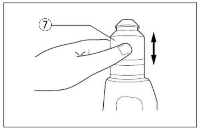
⑦ Chuck cover
Explanation of general view
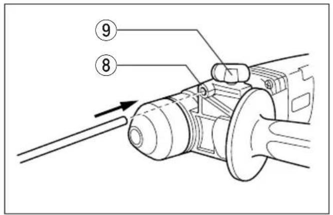
⑧ Hole
⑨ Clamp screw
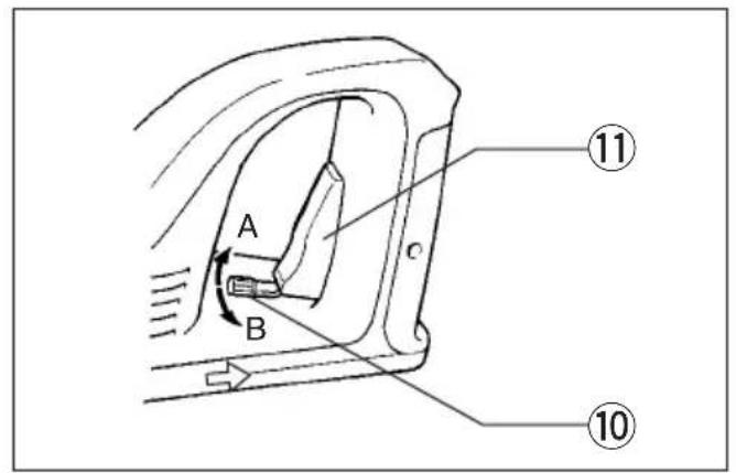
⑩ Reversing switch lever
⑪ Switch trigger
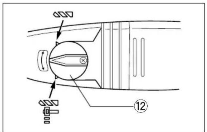
⑫ Action mode changing knob
⑬ Blow-out bulb
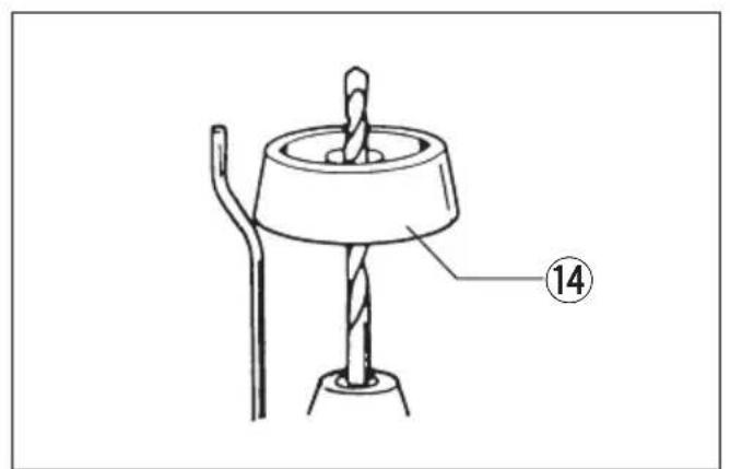
⑭ Dust cup
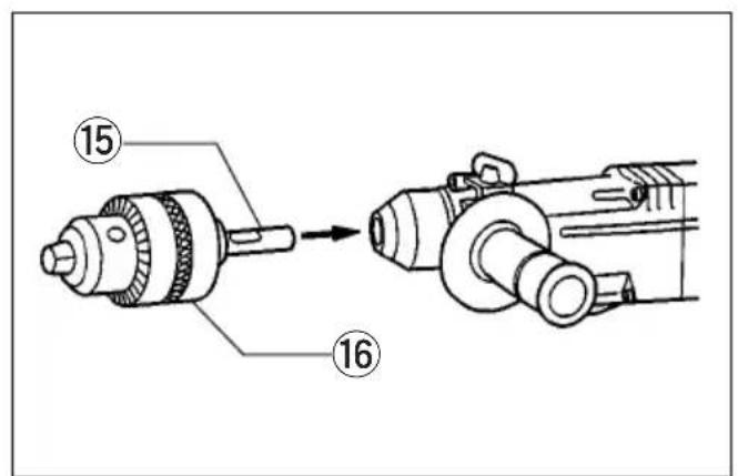
⑮ Chuck adapter
⑯ Drill chuck
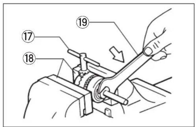
⑰ Chuck key
⑱ Soft jaws
⑲ Wrench
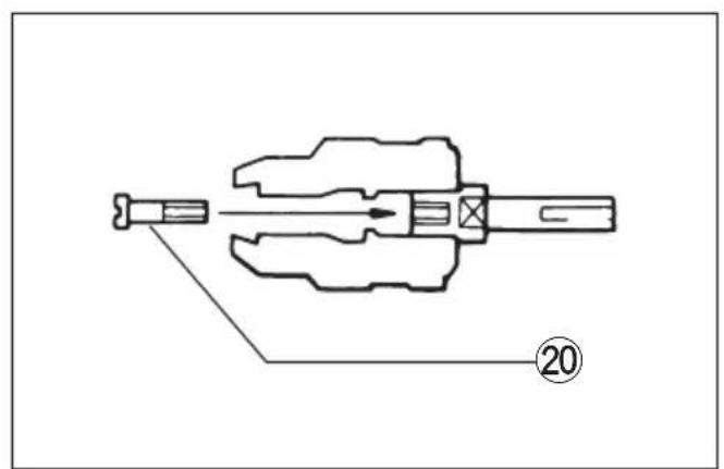
⑳ Screw
SPECIFICATIONS
Model HR2420
| Capacities | |
| Concrete | 24 mm |
| Steel | 13 mm |
| Wood | 32 mm |
| No load speed (RPM) | 0 - 1,050 |
| Blows per minute | 0 - 4,900 |
| Overall length | 432 mm |
| Net weight | 2.4 kg |
- Due to the continuing program of research and development, the specifications herein are subject to change without prior notice.
- Note: Specifications may differ from country to country.
Power supply
The machine should be connected only to a power supply of the same voltage as indicated on the nameplate, and can only be operated on single-pha AC supply. They are double-insulated in accordance with European Standard and can, therefore, also be used from sockets without earth wire.
Safety hints
For your own safety, please refer to enclosed safet instructions.
ADDITIONAL SAFETY RULES
- Wear a hard hat (safety helmet), safety glass and/or face shield. It is also highly recommended that you wear a dust mask, ear protectors and thickly padded gloves.
- Be sure the bit is secured in place before operation.
- Under normal operation, the machine is designed to produce vibration. The screws can come loose easily, causing a breakdown or accident. Check tightness of screws carefully before operation.
- In cold weather or when the machine has no been used for a long time, let the machine warm up for several minutes by operating it under no load. This will loosen up the lubrication. Without proper warm-up, hammering operation is difficult.
-
Always be sure you have a firm footing. Be sure no one is below when using the machine in high locations.
-
Hold the machine firmly with both hands.
-
Keep hands away from moving parts.
-
Do not leave the machine running. Operate the machine only when hand-held.
-
Do not point the machine at any one in the area when operating. The bit could fly out and injure someone seriously.
-
When drilling or chipping into walls, floors or wherever “live” electrical wires may be encountered, DO NOT TOUCH ANY METAL PARTS OF THE MACHINE! Hold the machine by the insulated grasping surfaces to prevent electric shock if you drill or chip into a “live” wire.
-
Do not touch the bit or parts close to the bit immediately after operation; they may be extremely hot and could burn your skin.
SAVE THESE INSTRUCTIONS.
OPERATING INSTRUCTIONS
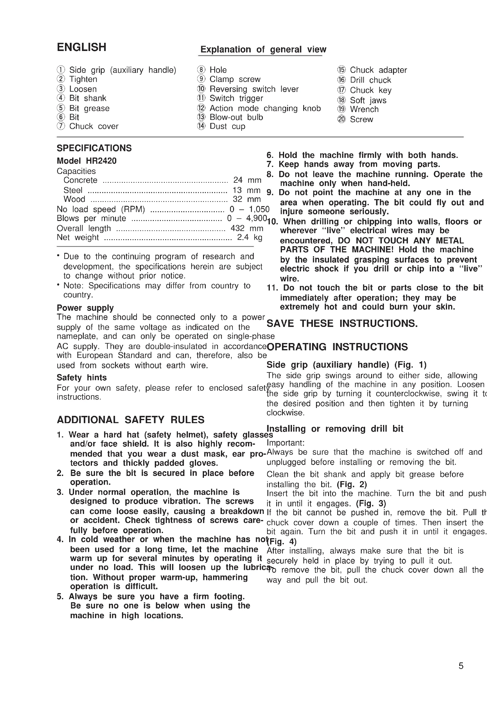
Side grip (auxiliary handle) (Fig. 1)
The side grip swings around to either side, allowing easy handling of the machine in any position. Loosen by the side grip by turning it counterclockwise, swing it to the desired position and then tighten it by turning clockwise.
Installing or removing drill bit
Important:
.Always be sure that the machine is switched off and unplugged before installing or removing the bit.
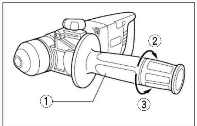
Clean the bit shank and apply bit grease before installing the bit. (Fig. 2)
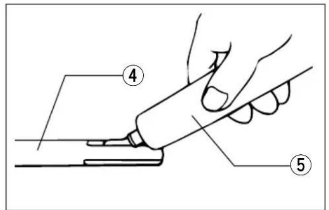
Insert the bit into the machine. Turn the bit and push it in until it engages. (Fig. 3)
If the bit cannot be pushed in, remove the bit. Pull the chuck cover down a couple of times. Then insert the bit again. Turn the bit and push it in until it engages.
After installing, always make sure that the bit is securely held in place by trying to pull it out.
To remove the bit, pull the chuck cover down all the way and pull the bit out.
Depth gauge (Fig. 5)
The depth gauge is convenient for drilling holes of uniform depth. Insert the depth gauge into the hole the grip base. Adjust the depth gauge to the desired depth and then tighten the clamp screw to secure depth gauge.
NOTE:
The depth gauge cannot be used at the position where the depth gauge strikes against the gear housing.
Switch action (Fig. 6)
CAUTION:
Before plugging in the machine, always check to say that the switch trigger actuates properly and returns the "OFF" position when released.
To start the machine, simply pull the trigger. Machi speed is increased by increasing pressure on the trigger. Release the trigger to stop.
Reversing switch action (Fig. 6)
CAUTION:
• Always check the direction of rotation before operation.
- Use the reversing switch only after the machine comes to a complete stop. Changing the direction rotation before the machine stops may damage the machine.
- Do not pull the switch trigger when the reversing switch lever is in the neutral position. If you pull trigger forcibly, the switch may be damaged.
This machine has a reversing switch to change the direction of rotation. Move the lever to the position (A position) for clockwise rotation or the position (B position) for counterclockwise rotation.
Selecting action mode (Fig. 7)
This machine employs an action mode changing knob. Select one of the two modes suitable for your work needs by using this knob. For rotation only, the knob so that the arrow on the knob points tow the symbol on the machine body. For rotation with hammering, turn the knob so that the arrow of the knob points toward the symbol on the machine body.
CAUTION:
Always set the knob fully to your desired mode symbol. If you operate the machine with the knob positioned half-way between the mode symbols, the machine may be damaged.
Torque limiter
The torque limiter will actuate when a certain torque level is reached. The motor will disengage from the output shaft. When this happens, the bit will stop thening.
CAUTION:
- As soon as the torque limiter actuates, switch off the machine immediately. This will help prevent premature wear of the machine.
- Hole saws, core bits, diamond core bits, etc. cannot be used with this machine. They tend to pinch or catch easily in the hole. This will cause the torque limiter to actuate too frequently.
Hammer drilling operation
Position the bit at the desired location for the hole, then pull the trigger. Do not force the machine. Light pressure gives best results. Keep the machine in position and prevent it from slipping away from the hole. Do not apply more pressure when the hole becomes clogged with chips or particles. Instead, run the machine at an idle, then remove the bit partially from the hole. By repeating this several times, the hole will be cleaned out and normal drilling may be resumed.
CAUTION:
There is a tremendous and sudden twisting force exerted on the machine/bit at the time of hole breakthrough, when the hole becomes clogged with chips and particles, or when striking reinforcing rods embedded in the concrete. Always use the side grip (auxiliary handle) and firmly hold the machine by both side grip and switch handle during operations. Failure to do so may result in the loss of control of the machine and potentially severe injury.
Bit grease
Coat the bit shank head beforehand with a small amount of bit grease (about 0.5–1 g).
This chuck lubrication assures smooth action and longer service life.
Blow-out bulb (Fig. 8)
Use the blow-out bulb to clean out the hole.
Dust cup (Fig. 9)
Use the dust cup to prevent dust from falling over the machine and on yourself when performing overhead drilling operations. Attach the dust cup to the bit as shown in Fig. 9. The dust cup can be attached to the bit up to 14.5 mm in diameter.
Drilling in wood or metal (Fig. 10)
Use the optional drill chuck assembly (consisting of drill chuck and chuck adapter assembly). When installing it, refer to "Installing or removing drill bit" described on the previous page. Set the action more changing knob to "rotation only". You can drill up to
13 mm diameter in metal and up to 32 mm diameter wood.
MAINTENANCE
CAUTION:
Always be sure that the machine is switched off and unplugged before carrying out any work on the machine.
To maintain product safety and reliability, repairs, maintenance or adjustment should be carried out by Makita Authorized Service Center.
CAUTION:
Never use “rotation with hammering” when the drill chuck assembly is installed on the machine. The drill chuck assembly may be damaged. Also, the drill chuck will come off when reversing the machine.
NOTE:
If you need to assemble the drill chuck and chuck adapter assembly, proceed as follows.
Secure the drill chuck in a vise or similar securing devise. Place the chuck key in one of the three holes so that the chuck body will not turn. (Fig. 11)
Remove the screw from the chuck adapter assembly and screw the chuck adapter into the drill chuck. Use a wrench to tighten the chuck adapter securely, applying about 300 - 400 kg torque. (Note: you can obtain 300 - 400 kg torque by applying pressure of 30 - 40 kg to the wrench while holding the portion 10 cm from the wrench head.)
Open the chuck jaws fully and insert the screw through the chuck opening. Tighten the screw counterclockwise with a screwdriver. (Fig. 12)
These accessories or attachments are recommended for use with your Makita machine specified in this manual. The use of any other accessories or attachments might present a risk of injury to persons. The accessories or attachments should be used only in the proper and intended manner.
F ACCESSOIRES
ATTENTION :
EC-DECLARATION OF CONFORMITY
The undersigned, Yasuhiko Kanzaki, authorized by Makita Corporation, 3-11-8 Sumiyoshi-Cho, Anjo, Aichi, 446 Japan declares that this product
(Serial No.: series production)
manufactured by Makita Corporation in Japan is in compliance with the following standards or standardized documents,
HD400, EN50144, EN55014, EN61000*
in accordance with Council Directives, 73/23/EEC, 89/336/EEC and 98/37/EC.
ITALIANO
DÉCLARATION DE CONFORMITÉ CE
Michigan Drive, Tongwell, Milton Keynes,
Bucks MK15 8JD, U.K.
PORTUGUÊS
EU-DEKLARATION OM KONFORMITET
Michigan Drive, Tongwell, Milton Keynes,
Bucks MK15 8JD, U.K.
ENGLISH
Noise And Vibration Of Model HR2420
The typical A-weighted noise levels are
sound pressure level: 90 dB (A)
sound power level: 103 dB (A)
- Wear ear protection. -
The typical weighted root mean square acceleration value is 8 m/s ^2 .