PTSS 1200 B1 - Electric saw PARKSIDE - Free user manual and instructions
Find the device manual for free PTSS 1200 B1 PARKSIDE in PDF.
| Product type | Plunge saw |
| Brand | Parkside |
| Model | PTSS 1200 B1 |
| Nominal voltage | 230 V~, 50 Hz |
| Nominal power | 1200 W |
| No-load speed | 5200 min⁻¹ |
| Blade diameter | 165 mm |
| Blade bore | 20 mm |
| Blade body thickness | 1.5 mm |
| Tooth thickness | 2.6 mm |
| Max. cutting depth (90°) | 56 mm (51 mm with guide rail) |
| Max. cutting depth (45°) | 42 mm (37 mm with guide rail) |
| Bevel angle | 0° to 45° |
| Protection class | II (double insulation) |
| Guide rails (length × width) | 2 × (700 mm × 180 mm) |
| Plunge cut | Yes |
| Chip extraction | Rotating ejection adapter |
| Auxiliary handle | Yes |
| Protective guard | With return spring |
| Warranty | 3 years |
| Sound pressure level | 91.23 dB(A) |
| Sound power level | 102.23 dB(A) |
| Vibration (main handle) | 4.202 m/s² |
| Vibration (auxiliary handle) | 5.050 m/s² |
Frequently Asked Questions - PTSS 1200 B1 PARKSIDE
User questions about PTSS 1200 B1 PARKSIDE
0 question about this device. Answer the ones you know or ask your own.
Ask a new question about this device
Download the instructions for your Electric saw in PDF format for free! Find your manual PTSS 1200 B1 - PARKSIDE and take your electronic device back in hand. On this page are published all the documents necessary for the use of your device. PTSS 1200 B1 by PARKSIDE.
USER MANUAL PTSS 1200 B1 PARKSIDE
text_image
PDF online www.lidl-service.com PARSIDE RKSIDE PASTERTAUCHSÄGE / PLUNGE SAW / SCIE PLONGEANTE PTSS 1200 B1
DE AT CH
TAUCHSÄGE
Translation of the original instructions
NL BE
CIRKELZAAG
Before reading, unfold the page containing the illustrations and familiarise yourself with all functions of the device.
FR BE
GB/IE Translation of the original instructions Page 13
natural_image
Technical diagram of a mechanical component with concentric rings and a central hexagonal nut (no text or symbols)Abb. A
KOMPERNASS HANDELS GMBH
BURGSTRASSE 21
DE - 44867 BOCHUM
GERMANY
www.kompernass.com
text_image
Jeddyush CESemi Uguzlu
General Power Tool Safety Warnings 15
- Work area safety 15
- Electrical safety 15
- Personal safety 16
- Power tool use and care 16
- Service 16
Appliance-specific safety instructions for circular saws 17
Further safety instructions for all saws 17
Original accessories/auxiliary equipment 19
Operation 19
Fitting/changing the saw blade 19
Connecting the sawdust extraction device 19
Check that the blade guard is functioning 19
Operation 19
Switching on and off 19
Setting the cutting depth (dive depth) 19
Setting the cutting angle (mitre angle) 20
Note the cut line 20
Eccentric screws 20
Sawing (without guide rail) 20
Sawing (with guide rail) 21
Plunge cutting with guide rail 21
Cleaning and maintenance 22
Disposal 22
Kompernass Handels GmbH warranty 22
Service 23
Importer 23
Translation of the original Conformity Declaration 24
PLUNGE SAW PTSS 1200 B1
Introduction
Congratulations on the purchase of your new appliance. You have selected a highquality product. The operating instructions are part of this product. They contain important information on safety, usage and disposal. Before using the product, familiarise yourself with all operating and safety instructions. Use the product only as described and for the specified areas of application. Please also pass on these operating instructions to any future owner.
Intended use
This circular saw (hereinafter "appliance" or "machine") is designed for longitudinal, cross and plunge cuts in firmly supported solid wood, chip board, plastics and lightweight construction materials. Working with metals is not permitted. This appliance can be used with the provided guide rails - exclusively for the cutting techniques described. Any other uses of or modification to the appliance is deemed to be improper and carries the risk of serious personal injury. Not for commercial use.
Features
① Safety lock-out
② ON/OFF switch
3Handle
4 Hex key (small)
5 Hex key (large)
6 Motor unit
7 Chip ejector adapter
8 Fine adjustment screws for 0° cutting angle
8a Fine adjustment screw for 45° cutting angle
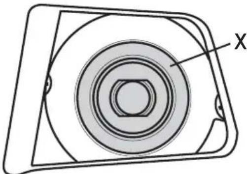
9 Baseplate
9a Markings for cutting line
10 Eccentric screw (2 x)
⑪ Adjustment wheel for cutting angle adjustment (2 x)
12 Cutting depth adjustment
13 Cutting depth scale
14 Saw blade
14a Clamping screw/plain washer
14b Panel cut out
15 Additional handle
16 Cutting width marking
17 Chip ejector (rotatable)
18 Clamping lever for changing saw blades
19 Spindle lock
20 Groove for guide rails
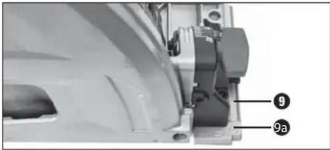
21 Guide rail
22 Grub screws
23 Connector
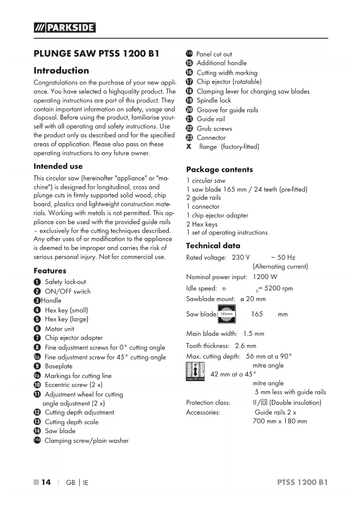
X flange (factory-fitted)
Package contents
1 circular saw
1 saw blade 165 mm / 24 teeth (pre-fitted)
2 guide rails
1 connector
1 chip ejector adapter
2 Hex keys
1 set of operating instructions
Technical data
Rated voltage: 230 V \~ 50 Hz (Alternating current)
Nominal power input: 1200 W
Idle speed: n _0 = 5200 rpm
Sawblade mount: ∅ 20 mm

Main blade width: 1.5 mm
Tooth thickness: 2.6 mm
Max. cutting depth: 56 mm at a 90°

42 mm at a 45^
mitre angle
5 mm less with guide rails
Protection class: II/☐ (Double insulation)
Accessories: Guide rails 2 x 700 mm x 180 mm
Noise emission value:
Noise measurement value determined in accordance with EN 60745. The A-rated noise level of the power tool is typically as follows:
Sound pressure level: L_PA = 91.23 dB (A)
Uncertainty: K = 3 dB (A)
Sound power level: L _WA = 102.23 dB (A)
Uncertainty: K = 3 dB (A)

hearing protection!
Vibration values:
Vibration values (vector total of three directions) determined in accordance with EN 60745:
Cutting chipboard: Main handle a_h,w=4.202 m/s^2
Auxiliary handle q_h,w = 5.050 m/s^2
Uncertainty K = 1.5 m/s ^2
NOTE
The vibration level specified in these instructions has been measured in accordance with a standardised measuring procedure specified in EN 60745 and can be used to make equipment comparisons. The specified vibration emission value can also be used to make an initial exposure estimate.

WARNING!
The vibration level varies in accordance with the use of the power tool and may be higher than the value specified in these instructions in some cases. There is a risk of underestimation of the vibration load if the power tool is used regularly in this manner. Try to keep the vibration loads as low as possible. Measures to reduce the vibration load include wearing gloves and limiting your working time.
All states of operation must be taken into account (e.g. times when the power tool is switched off and times where the power tool is switched on but running without load).

eral Power Tool Safety Warnings


WARNING!
▶ Read all safety warnings and all instructions. Failure to follow the warnings and instructions may result in electric shock, fire and/or serious injury.
Save all warnings and instructions for future reference.
The term "power tool" in the warnings refers to your mains-operated (corded) power tool or battery-operated (cordless) power tool.
1. Work area safety
a) Keep work area clean and well lit. Cluttered or dark areas invite accidents.
b) Do not operate power tools in explosive atmospheres, such as in the presence of flammable liquids, gases or dust. Power tools create sparks which may ignite the dust or fumes.
c) Keep children and bystanders away while operating a power tool. Distractions can cause you to lose control.
2. Electrical safety
a) Power tool plugs must match the outlet.
Never modify the plug in any way.
Do not use any adapter plugs with earthed (grounded) power tools Unmodified plugs and matching outlets will reduce risk of electric shock.
b) Aoid body contact with earthed or grounded surfaces, such as pipes, radiators, ranges and refrigerators. There is an increased risk of electric shock if your body is earthed or grounded.
c) Do not expose power tools to rain or wet conditions. Water entering a power tool will increase the risk of electric shock.
d) Do not abuse the cord. Never use the cord for carrying, pulling or unplugging the power tool. Keep cord away from heat, oil, sharp edges or moving parts. Damaged or entangled cords increase the risk of electric shock.
e) When operating a power tool outdoors, use an extension cord suitable for outdoor use. Use of a cord suitable for outdoor use reduces the risk of electric shock
f) If operating a power tool in a damp location is unavoidable, use a residual current device (RCD) protected supply. Use of an RCD reduces the risk of electric shock.
3. Personal safety
a) Stay alert, watch what you are doing and use common sense when operating a power tool. Do not use a power tool while you are tired or under the influence of drugs, alcohol or medication. A moment of inattention while operating power tools may result in serious personal injury.
b) Use personal protective equipment. Always wear eye protection Protective equipment such as dust mask, non-skid safety shoes, hard hat, or hearing protection, depending on the type and use of the electric tool, will reduce the risk of personal injuries.
c) Prevent unintentional starting. Ensure the switch is in the off position before connecting to power source and/or battery pack, picking up or carrying the tool. Carrying power tools with your finger on the switch or energising power tools that have the switch on invites accidents.
d) Remove any adjusting key or wrench before turning the power tool on. A wrench or a key left attached to a rotating part of the power tool may result in personal injury.
e) Do not overreach. Keep proper footing and balance at all times. This enables better control of the power tool in unexpected situations.
f) Dress properly. Do not wear loose clothing or jewellery. Keep your hair, clothing and gloves away from moving parts. Loose clothes, jewellery or long hair can be caught in moving parts.
g) If devices are provided for the connection of dust extraction and collection facilities, ensure these are connected and properly used. Use of dust collection can reduce dust-related hazards.
4. Power tool use and care
a) Do not force the power tool. Use the correct power tool for your intended application. The correct power tool will do the job better and safer at the rate for which it was designed.
b) Do not use the power tool if the switch does not turn it on and off. Any power tool that cannot be controlled with the switch is dangerous and must be repaired.
c) Disconnect the plug from the power source and/or the battery pack from the power tool before making any adjustments, changing accessories, or storing power tools. Such preventive safety measures reduce the risk of starting the power tool accidentally.
d) Store idle power tools out of the reach of children and do not allow persons unfamiliar with the power tool or these instructions to operate the power tool. Power tools are dangerous in the hands of untrained users.
e) Maintain power tools. Check for misalignment or binding of moving parts, breakage of parts and any other condition that may affect the power tool's operation. If damaged, have the power tool repaired before use. Many accidents are caused by poorly maintained power tools.
f) Keep cutting tools sharp and clean. Properly maintained cutting tools with sharp cutting edges are less likely to bind and are easier to control.
g) Use the power tool, accessories and tool bits etc. in accordance with these instructions, taking into account the working conditions and the work to be performed. Use of the power tool for operations different from those intended could result in a hazardous situation.
5. Service
a) Have your power tool serviced by a qualified repair person using only identical replacement parts. This will ensure that the safety of the power tool is maintained.
Appliance-specific safety instructions for circular saws
Cutting procedures
a) Danger! Keep your hands clear of the sawing area and the saw blade. Hold the auxiliary handle or motor housing with your other hand. When both hands are being used to hold the saw, neither can be injured by the saw blade.
b) Do not reach underneath the workpiece. The blade guard cannot protect you from the saw blade below the workpiece.
c) Adapt the cutting depth to the thickness of the workpiece. Less than a full tooth height should be visible below the workpiece.
d) Never hold the workpiece to be sawn in your hand or over your leg. Fasten the workpiece to a stable working surface. It is important to fasten the workpiece securely to minimise the danger of bodily contact, jamming of the saw blade or loss of control.
e) Hold the power tool by insulated gripping surfaces only, when performing an operation where the cutting tool may contact hidden wiring or its own cord. Contact with a live wire will also make exposed metal parts of the power tool live and could give the operator an electric shock.
f) When making longitudinal cuts, always use a guide rail or a straight edge guide. This will improve the accuracy of your cut and reduce the likelihood of the saw blade jamming.
g) Always use saw blades with the correct size and shape (diamond versus round) of arbour holes. Blades that do not match the mounting hardware of the saw will run eccentrically, causing loss of control.
h) Never use damaged or incorrect saw blade washers or screws. The saw blade washers and screws have been specially designed for your saw to provide optimum performance and operational safety.
Further safety instructions for all saws
Kickback causes and corresponding safety instructions
-A kickback is a sudden reaction caused as a result of the saw blade catching, jamming or being falsely aligned, causing the saw to jump up uncontrollably and out of the workpiece in the direction of the operator;
-if the saw blade catches or jams in a narrowing saw cut, the blade can no longer rotate and the power of the motor throws the appliance back in the direction of the operator;
- if the saw blade twists in the saw cut or becomes misaligned, the teeth at the rear edge of the saw blade can become caught in the surface of the workpiece, causing the saw blade to jump out of the cut and the saw to jump backwards in the direction of the operator.
A kickback is caused by incorrect use or misuse of the saw. This can be avoided by taking proper precautions as given below.
a) Hold the saw firmly in both hands and position your arms so that they can absorb the force of a kickback. Position your body to either side of the saw blade, never in line with the saw blade. If a kickback occurs, the circular saw may jump backwards. However, by taking appropriate precautions the operator can control the kickback forces.
b) If the saw blade jams or you stop working, switch the saw off and hold it steadily in the workpiece until the saw blade has completely stopped turning. Never attempt to remove the saw from the workpiece or pull it backwards while the saw blade is still moving as this could lead to a kickback. Investigate and take corrective actions to eliminate the cause of blade binding.
c) If you want to restart a saw that is still in the workpiece, centre the saw blade in the cut and check to ensure that the teeth are not caught anywhere in the workpiece. If the saw blade catches it can jump out of the workpiece or cause a kickback when the saw is restarted.
d) Support large panels or boards to reduce the risk of the saw blade jamming and causing a kickback. Large panels tend to bend under their own weight. Panels must be supported on both sides, in the vicinity of the saw cut and also at the edge.
e) Do not use blunt or damaged saw blades. Saw blades with blunt or misaligned teeth may cause excessive friction as the saw cut is too narrow, and this can cause a saw blade jam and kickback.
f) Blade depth and bevel adjusting locking levers must be tight and secure before making cut. If the settings change while sawing, the saw blade might jam and cause a kickback.
g) Be particularly careful when sawing in existing walls or other obscured areas. The inserted saw blade could get caught on hidden objects and cause a kickback.
Function of the blade guard
a) Before every use, check to ensure that the blade guard closes properly. Do not use the saw if the blade guard does not move freely and does not close immediately. Never clamp or tie the blade guard into the open position. If the saw accidentally falls to the floor, the blade guard might bend. Ensure that the blade guard moves freely and does not touch the saw blade or other parts at all cutting angles or depths.
b) Check the operation of the blade guard spring If the guard and the spring are not operating properly, have the appliance serviced before using it. Damaged parts, sticky deposits or accumulations of chippings can cause the blade guard to operate slowly.
c) When making a "plunge cut" which is not at right angles, secure the saw base plate to prevent any lateral movement. Lateral movement can cause the saw blade to jam, thus causing a kickback.
d) Do not leave the saw on the work bench or floor if the blade guard is not fully covering the saw blade. An unprotected, coasting saw blade will move the saw in the opposite direction to the cutting direction and saw anything in its path. Be aware of the time it takes for the blade to stop after switch is released.
Supplementary notes
■ Do not use any grinding discs.
■ Use only saw blades with diameters corresponding to the label on the saw.
WARNING! DANGER DUE TO DUST EXPOSURE!
▶ When working for extended periods of time on wood and, in particular, materials that produce dust which is hazardous to health, connect the appliance to an appropriate external dust extraction appliance.

Wear protective gloves!

Wear a dust mask!

Wear safety goggles!

Wear ear protectors!
■ Do not allow the teeth of the saw blade to overheat.
■ When sawing plastic, avoid melting the plastic.
WARNING! TOXIC FUMES!
▶ Working with the tool can produce harmful/toxic dusts that represent a health hazard for the person operating the appliance and for any other people in the area.
■ Materials containing asbestos may not be processed. Asbestos is a known carcinogen.
Original accessories/auxiliary equipment
■ Use only the additional equipment and accessories specified in the operating instructions. Using attachments or accessory tools other than those recommended in the operating instructions can lead to a risk of injury.
■ Only the original guide rails may be used.
■ All blades used should conform to EN 847-1.
Operation
Fitting/changing the saw blade
Always remove the plug from the power socket before working on the appliance.
NOTE
▶ Position the base plate for this operation on the edge of a stable surface so that the saw blade 14 can be lowered.
- Activate the safety lock-out and push the motor unit forwards.
- Open the clamping lever ^18 . Release the safety lock-out ① The motor unit clicks into place. The movement of the motor unit is blocked upward and downward.
- The clamping screw/washer ^14a is now in position 14b.
- Press the spindle lock button ^19 and use the Hex key 5 to open the clamping screw/washer 14a.
- Remove saw blade ^14 .
NOTE
▶ Ensure that the factory-fitted flange X stays in place during installation and removal (see fig. A).
natural_image
Technical diagram of a mechanical component with concentric rings and a central hexagonal nut (no text or symbols)Fig. A
- Fitting a saw blade ^14 is carried out in the reverse order.

WARNING!
The direction of rotation of the saw blade and the machine must match.
Connecting the sawdust extraction device
If required, attach the adapter for dust extraction ⑦ to the chip ejector . ⑰
- Connect an approved dust and chip extraction device.
Check that the blade guard is functioning
NOTE
▶ Position the base plate for this operation on the edge of a stable surface so that the saw blade 14 can be lowered.
◆ Activate the safety lock-out and lower the circular saw.
Check whether the saw blades ^14 rubs against the blade guard and whether it moves back to its starting position automatically.
Operation
Switching on and off
Switching on:
♦ Push the safety lock-ou ^1 upwards and hold it in position.
◆ Press the ON/OFF switch ^2 . Once the saw is running, you can release the safety lock-out ^1
Switching off:
◆ Release the ON/OFF switch ^2 .
Setting the cutting depth (dive depth)
- Undo the screw for the cutting depth adjustment 12 and push the stop to the desired cutting depth on the cutting depth scale 13
-without guide rail, see mark A.
-with guide rail, see mark B.
◆ Retighten the screw for the cutting depth adjustment 12.
NOTE
▶ Adjust the cutting depth to the thickness of the workpiece. Less than a full tooth height should be visible below the workpiece.
Setting the cutting angle (mitre angle)
◆ Loosen the two adjustment wheels for the cutting angle 11
◆ Tilt the motor to the desired cutting angle.
◆ Retighten the adjustment wheel⑪.
NOTE
If you have set the cutting angle adjustment to 0^ or 45^ , you can use the fine adjustment screws 8 and 8a to make any fine adjustment that you require.
Note the cut line
◆ Cut line marking ^9a of 0°/45° are imprinted into the base plate ^9
♦ Align the appliance to the corresponding 0^ or 45^ cut line markings 9a in accordance with the set cutting angle.
◆ The inclined surfaces are reference points for this.
text_image
9 9a♦ Connecting the guide rails
The guide rails 21 will help you to make straight cuts.
To connect the 2 guide rails, push the connector ②3 into the groove of the guide rails. Tighten the grub screws ②2sing the Hex key supplied.
text_image
23 4 22NOTE
The guide rail?1 have a splinter guard (black rubber lip). The splinter guard must be adjusted before making the first cut. Place the guide rail onto a workpiece. Set a cutting depth of approx. 10 mm. Switch the circular saw on and push it gently and evenly in the cutting direction.
Eccentric screws
The eccentric screws 10 are intended for adjusting the fit of the base plate 9 in the guide rail . 21
♦ Tighten the eccentric screws to reduce the play between the circular saw and the guide rails 21
Sawing (without guide rail)
Right-angled sawing
◆ Hold the machine with both hands firmly on the handles ③ and ⑮
Switch on the appliance as described in "Switching on and off".
Place the appliance with the front part of the base plate ⑨ on the workpiece.
◆ Swivel the motor down and saw forwards with moderate pressure – never backwards.
Adjust the cutting angle as described.
◆ Hold the machine with both hands firmly on the handles ③ and ⑮
Switch on the appliance as described in "Switching on and off". Place the appliance with the front part of the base plate ⑨ on the workpiece.
◆ Swivel the motor down and saw forwards with moderate pressure – never backwards.
Plunge cuts
When making a "plunge cut" which is not at right angles, secure the base plate of the saw to prevent any lateral movement. Lateral movement can cause the saw blade to jam, thus causing a kickback.
Adjust the desired cutting depth as described above.
◆ Place the appliance on the workpiece.
- Avoid kickback and place the rear edge against a stop (as referenced in the section "Plunge cutting with guide rail").
Switch on the appliance as described in "Switching on and off".
Hold the machine with both hands firmly on the handles ③ and ⑪ and pivot it.
NOTE
The cut width marking 16 on the side of the blade guard shows the front and rear cutting point of a 165 mm at maximum cutting depth. This applies both to plunge cuts with guide rail 2nd plunge cuts without guide rail 21
Sawing (with guide rail)
Right-angled sawing with guide rail
Place the guide rail21 with the foam rubber element on the workpiece.
◆ Place the appliance with the groov 20 onto the guide rail 21
♦ Switch on the appliance as described in "Switching on and off".
Hold the machine with both hands firmly on the handles ③ and ⑮ and pivot it.
- Apply the guide rail with the foam rubber element onto the workpiece.
◆ Place the appliance with the groove onto the guide rail 21
Adjust the cutting angle as described.
◆ Hold the machine with both hands firmly on the handles ③ and ⑮
Switch on the appliance as described in "Switching on and off". Place the appliance with the front part of the base plate ⑨ on the workpiece.
◆ Swivel the motor down and saw forwards with moderate pressure – never backwards.
Plunge cutting with guide rail
◆ Place the guide rail with the foam rubber element on the workpiece.
◆ Place the appliance with the groove onto the guide rail 21
Adjust the desired cutting depth as described above.
◆ Place the rear edge (as much as possible) against a stop.
◆ Switch on the appliance as described in "Switching on and off".
Hold the machine with both hands firmly on the handles ③ and ⑮ and pivot it.
NOTE
The cut width marking 16 on the side of the blade guard shows the front and rear cutting point of a 165 mm cutting blade at maximum cutting depth. This applies both for plunge cuts with guide rail 21 and plunge cuts without guide rail 21
Further applications are not permitted.
Cleaning and maintenance

NING! RISK OF INJURY! Switch the appliance off and remove the power plug before starting any work on the appliance.
■ The appliance must always be kept clean, dry and free from oil or grease.
■ Use a soft, dry cloth to clean the housing.
NOTE
▶ Replacement parts not listed (such as carbon brushes, switches) can be ordered via our service hotline.
Disposal

ckaging is made from environmen- tally friendly material and can be disposed off at your local recycling plant.

dispose of power tools in your normal household waste!
European Directive 2012/19/EU requires that worn-out power tools be collected separately and recycled in an environmentally compatible manner.
This appliance has a 3-year warranty valid from the date of purchase. If this product has any faults, you, the buyer, have certain statutory rights. Your statutory rights are not restricted in any way by the warranty described below.
Warranty conditions
The validity period of the warranty starts from the date of purchase. Please keep your original receipt in a safe place. This document will be required as proof of purchase.
If any material or production fault occurs within three years of the date of purchase of the product, we will either repair or replace the product for you at our discretion. This warranty service is dependent on you presenting the defective appliance and the proof of purchase (receipt) and a short written description of the fault and its time of occurrence.
If the defect is covered by the warranty, your product will either be repaired or replaced by us. The repair or replacement of a product does not signify the beginning of a new warranty period.
Warranty period and statutory claims for defects
The warranty period is not prolonged by repairs effected under the warranty. This also applies to replaced and repaired components. Any damage and defects present at the time of purchase must be reported immediately after unpacking. Repairs carried out after expiry of the warranty period shall be subject to a fee.
Scope of the warranty
This appliance has been manufactured in accordance with strict quality guidelines and inspected meticulously prior to delivery.
The warranty covers material faults or production faults. The warranty does not extend to product parts subject to normal wear and tear or fragile parts such as switches, batteries, baking moulds or parts made of glass.
The warranty does not apply if the product has been damaged, improperly used or improperly maintained. The directions in the operating instructions for the product regarding proper use of the product are to be strictly followed. Uses and actions that are discouraged in the operating instructions or which are warned against must be avoided.
This product is intended solely for private use and not for commercial purposes. The warranty shall be deemed void in cases of misuse or improper handling, use of force and modifications/repairs which have not been carried out by one of our authorised Service centres.
Warranty claim procedure
To ensure quick processing of your case, please observe the following instructions:
■ Please have the till receipt and the item number (e.g. IAN 12345) available as proof of purchase.
■ You will find the item number on the type plate, an engraving on the front page of the instructions (bottom left), or as a sticker on the rear or bottom of the appliance.
If functional or other defects occur, please contact the service department listed either by telephone or by e-mail.
■ You can return a defective product to us free of charge to the service address that will be provided to you. Ensure that you enclose the proof of purchase (till receipt) and information about what the defect is and when it occurred.
You can download these instructions along with many other manuals, product videos and software on www.lidl-service.com.
Service
WARNING!
▶ Have the power tool repaired by the Service centre or a qualified electrician and only using original replacement parts. This will ensure that the safety of the appliance is maintained.
▶ Always ensure that the power plug or the mains cable is replaced only by the manufacturer of the appliance or by an approved customer service provider. This will ensure that the safety of the appliance is maintained.
GB Service Great Britain
Tel.: 0871 5000 720 (£ 0.10/Min.)
E-Mail: kompernass@lidl.co.uk
IE Service Ireland
Tel.: 1890 930 034
(0,08 EUR/Min., (peak))
(0,06 EUR/Min., (off peak))
E-Mail: kompernass@lidl.ie
IAN 290795
Importer
Please note that the following address is not the service address. Please use the service address provided in the operating instructions.
KOMPERNASS HANDELS GMBH
BURGSTRASSE 21
DE-44867 BOCHUM
GERMANY
www.kompernass.com
Translation of the original Conformity Declaration
We, KOMPERNASS HANDELS GMBH, documents officer: Mr. Semi Uguzlu, BURGSTR. 21, DE - 44867 BOCHUM, GERMANY, hereby de- clare that this product complies with the following standards, normative documents and EC directives:
Machinery Directive (2006/42/EC)
EMC (Electromagnetic Compatibility) (2014/30/EU)
RoHS Directive (2011/65/EU)*
* The manufacturer bears the full responsibility for compliance with this conformity declaration. The object of the declaration described above complies with the requirements of the Directive 2011/65/EU of the European Parliament and Council of 8 June 2011 on the limitations of use of certain dangerous substances in electrical and electronic appliances.
Applied harmonised standards:
EN 60745-1:2009+A11
EN 60745-2-5: 2010
EN ISO 12100: 2010
EN 55014-1:2006+A1+A2
EN 55014-2: 2015
EN 61000-3-2: 2014
EN 61000-3-3: 2013
Type/appliance designation:
Plunge saw PTSS 1200 B1
Year of manufacture: 10 - 2017
Serial number: IAN 290795
Bochum, 26/10/2017

text_image
JoddyjoukCE
Semi Uguzlu
- Quality Manager -
The right to effect technical changes in the context of further development is reserved.
Table des matières
Introduction 26
Incertitude: K = 3 dB (A)
Niveau de puissance
Incertitude: K = 3 dB (A)

natural_image
Technical diagram of a mechanical component with concentric rings and a central hexagonal feature, labeled 'X' (no text or symbols beyond label)Fig. A
KOMPERNASS HANDELS GMBH
BURGSTRASSE 21
DE-44867 BOCHUM
ALLEMAGNE
www.kompernass.com
WAARSCHUWING! RISICO DOOR STOF!
WAARSCHUWING! GIFTIGE DAMPEN!
natural_image
Technical diagram of a mechanical component with concentric rings and a central hexagonal nut (no text or symbols)Afb. A
KOMPERNASS HANDELS GMBH
BURGSTRASSE 21
DE-44867 BOCHUM
DUITSLAND
www.kompernass.com
text_image
Jed FyondCE
Semi Uguzlu
natural_image
Technical diagram of a mechanical component with concentric rings and mounting holes (no text or symbols)Obr. A
KOMPERNASS HANDELS GMBH
BURGSTRASSE 21
DE-44867 BOCHUM
NĚMECKO
www.kompernass.com
mango principal a_h,w = 4,202 m/s^2
mango auxiliar a_h,w=5,050 m/s^2
Incertidumbre K = 1,5 m/s ^2
INDICACIÓN
natural_image
Technical diagram of a mechanical component with concentric rings and a central hexagonal nut (no text or symbols)Fig. A
KOMPERNASS HANDELS GMBH
BURGSTRASSE 21
DE-44867 BOCHUM
ALEMANIA
www.kompernass.com
text_image
Sofitzky CESemi Uguzlu
natural_image
Technical diagram of a mechanical component with concentric rings and mounting holes (no text or symbols)Fig. A
KOMPERNASS HANDELS GMBH
BURGSTRASSE 21
DE-44867 BOCHUM
ALEMANHA
www.kompernass.com
KOMPERNASS HANDELS GMBH
BURGSTRASSE 21
44867 BOCHUM
DEUTSCHLAND / GERMANY
www.kompernass.com
Stand der Informationen · Last Information Update · Version des informations
Stand van de informatie · Stav informací · Estado de las informaciones