Bolero Squad IH 4800 TotalFlex80 - Cooker CECOTEC - Free user manual and instructions
Find the device manual for free Bolero Squad IH 4800 TotalFlex80 CECOTEC in PDF.
| Features | Details |
|---|---|
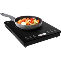
| Type of cooker | Induction cooker |
| Total power | 4800 W |
| Number of burners | 4 burners |
| Dimensions | Width: 80 cm, Depth: 60 cm |
| Surface material | Glass-ceramic |
| Additional features | TotalFlex function, timer, child safety |
| Usage | Compatible with all types of pots and pans suitable for induction |
| Maintenance | Easy cleaning with a damp cloth, no abrasive products |
| Safety | Automatic shut-off, overheating protection |
| Warranty | 2 years |
Frequently Asked Questions - Bolero Squad IH 4800 TotalFlex80 CECOTEC
User questions about Bolero Squad IH 4800 TotalFlex80 CECOTEC
0 question about this device. Answer the ones you know or ask your own.
Ask a new question about this device
Download the instructions for your Cooker in PDF format for free! Find your manual Bolero Squad IH 4800 TotalFlex80 - CECOTEC and take your electronic device back in hand. On this page are published all the documents necessary for the use of your device. Bolero Squad IH 4800 TotalFlex80 by CECOTEC.
USER MANUAL Bolero Squad IH 4800 TotalFlex80 CECOTEC
text_image
Technical diagram showing a vertical panel with circular elements and numerical values, likely representing a mechanical or electrical component.Safety instructions 9
-
Parts and components 75
-
Before use 75
-
Appliance installation 76
-
Operation 80
-
Cleaning and maintenance 89
-
Troubleshooting 92
-
Technical specifications 98
-
Disposal of old electrical and electronic appliances 100
-
Technical support and warranty 100
-
Copyright 100
SOMMAIRE
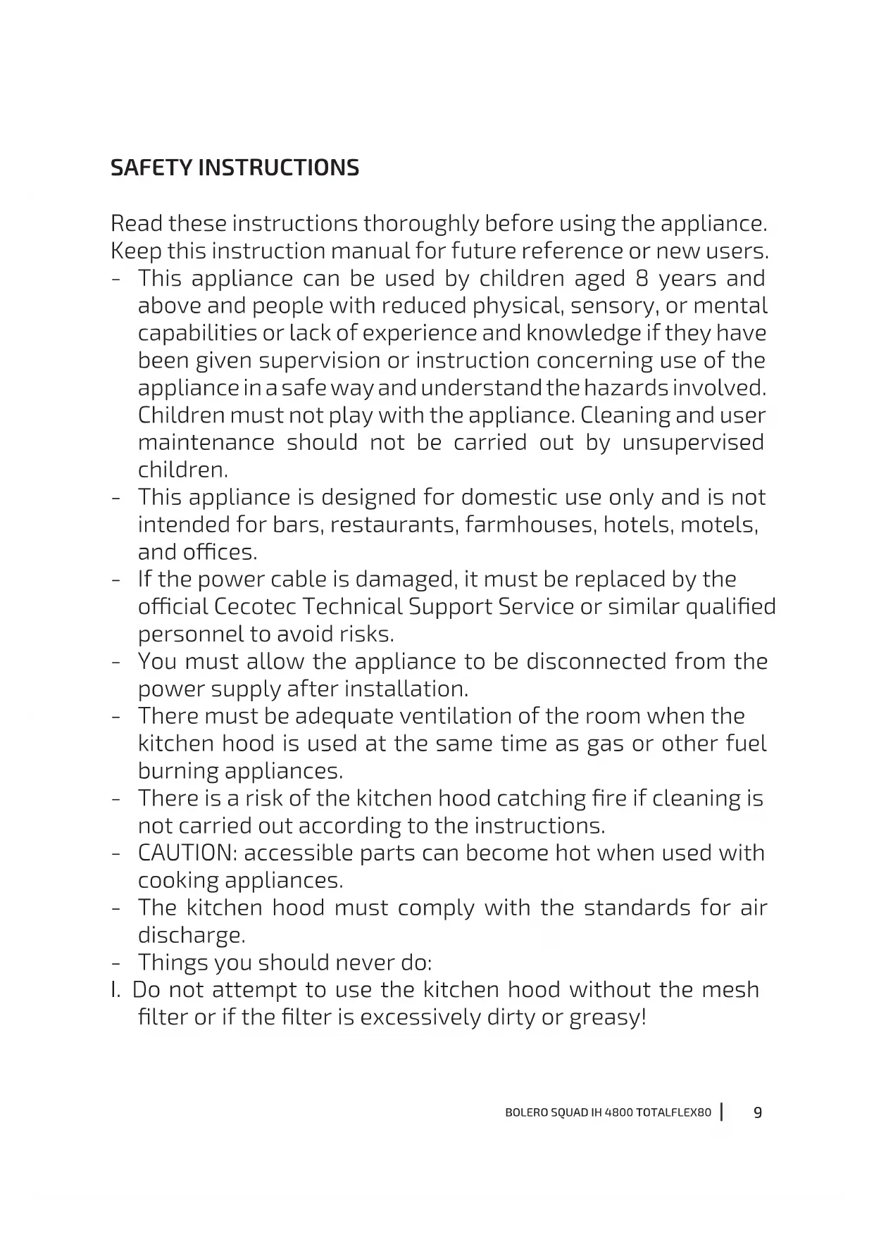
Read these instructions thoroughly before using the appliance. Keep this instruction manual for future reference or new users.
- This appliance can be used by children aged 8 years and above and people with reduced physical, sensory, or mental capabilities or lack of experience and knowledge if they have been given supervision or instruction concerning use of the appliance in a safe way and understand the hazards involved. Children must not play with the appliance. Cleaning and user maintenance should not be carried out by unsupervised children.
- This appliance is designed for domestic use only and is not intended for bars, restaurants, farmhouses, hotels, motels, and offices.
- If the power cable is damaged, it must be replaced by the official Cecotec Technical Support Service or similar qualified personnel to avoid risks.
- You must allow the appliance to be disconnected from the power supply after installation.
- There must be adequate ventilation of the room when the kitchen hood is used at the same time as gas or other fuel burning appliances.
- There is a risk of the kitchen hood catching fire if cleaning is not carried out according to the instructions.
- CAUTION: accessible parts can become hot when used with cooking appliances.
- The kitchen hood must comply with the standards for air discharge.
- Things you should never do:
I. Do not attempt to use the kitchen hood without the mesh filter or if the filter is excessively dirty or greasy!
II. Do not install the kitchen hood above a cooker with a high level grill.
III. Do not leave pans unattended during use because overheated fats or oils may catch fire.
- Accumulation of grease in the kitchen hood can cause a fire hazard. Clean the appliance according to the instructions in this manual.
- Exercise extreme caution when cleaning the appliance. Risk of burns and/or cuts. We recommend the use of gloves.
- Never leave open flames.
- If the kitchen hood is damaged, do not attempt to use it.
- When the kitchen hood and other non-electrically powered appliances are in simultaneous operation, the negative pressure in the room must not exceed 4 Pa (4 x 10 ^-5 bar).
- Important! Always disconnect the power supply during installation and maintenance.
- The kitchen hood must be installed in accordance with the installation instructions and in compliance with all measurements.
- All installation work must be carried out by a competent person or a qualified electrician.
- Dispose of the packaging material carefully. Children are vulnerable to it.
- Pay attention to sharp edges inside the kitchen hood, especially during installation and cleaning.
- Warning: Before accessing the electrical terminals, all power supply circuits must be disconnected.
- There must be adequate ventilation of the room when the kitchen hood is used at the same time as gas or other fuel burning appliances.
-
Caution: The appliance and its accessible parts may become hot during operation. Be careful not to touch any accessible parts.
-
Local air discharge regulations must be complied with.
- You should not use a steam cleaner.
- NEVER try to put out the fire with water. Instead, turn off the appliance and smother the flame with, e.g., a fireproof lid or blanket.
- Never use extension leads, multiple socket connections or external timer connection elements.
- If the power cable is damaged, it must be replaced by the official Cecotec Technical Support Service or by similarly qualified technicians to prevent hazards.
- The appliance must not be operated if the power supply cable is damaged or cut.
- If the appliance stops working or malfunctions abnormally, disconnect it from the mains and contact the official Cecotec Technical Support Service.
- Cecotec disclaims all liability for any damage or injury caused as a result of failure to follow the installation and/or operating instructions contained in this instruction manual.
- This symbol means “caution, hot surface.” The temperature of the accessible surfaces of the hob may be high when the appliance is in operation.
- WARNING: If the hob surface is cracked, turn off the appliance to avoid the possibility of electric shock. Contact the official Cecotec Technical Support Service. Do not cook on a cracked or broken hob.
- Do not use harsh abrasive cleaners or sharp metal scrapers to clean the hob glass, as they may scratch the surface, which could result in glass breakage.
- The appliance is not intended to be operated by means of an external timer or separate remote-control system.
-
Risk of fire: Do not store objects on the cooking surfaces of the hob.
-
CAUTION: the cooking process must be supervised. A short-term cooking process must be continuously monitored.
- WARNING: Unattended cooking on a greasy or oily hob can be dangerous and could result in a fire.
- WARNING: unsupervised cooking on a cooking hob with grease or oil may be dangerous and cause a fire. Never try to put out the fire with water, switch off the appliance and cover the flame, for example, with a lid or a fireproof blanket.
- Unplug the cooking hob before carrying out any cleaning or maintenance task.
- The appliance must not be installed behind a decorative door to avoid overheating.
- Ensure that the mains voltage matches the voltage specified on the device rating label and that the plug is earthed.
- Be careful: the edges of the hob panel are sharp. Failure to exercise caution may result in injury or cuts.
- Do not place any flammable material or product on this appliance at any time.
- It is recommended that a suitably qualified person installs and connects the appliance correctly.
- The hob must be connected to a circuit incorporating an isolator that allows complete disconnection from the mains.
- If the appliance is not correctly installed, any guarantee or liability claims may be voided.
- If the cable is damaged, it must be replaced by the manufacturer, the supplier, or qualified personnel to avoid hazards.
- The cookware handles may be hot to the touch after use on the hob. Check the cookware handles do not overlap other cooking zones that are on. Keep the handles out of the reach of children. Failure to follow this advice may result in burns.
- After use, always turn off the cooking zones and the hob as described in this manual.
- WARNING: the appliance and its accessible parts become hot during use. Be careful not to touch the heating elements. Children under 8 years old must stay away from the appliance, unless they are constantly supervised.
INSTRUCTIONS DE SÉCURITÉ
- 2200/3600 W zone
- 2200/3600 W zone
- 2200/3600 W zone
- 2200/3600 W zone
- 3300/3700 W zone
- 3300/3700 W zone
- Control panel
Control panel
Fig. 2
A1. Left flex zone icon
A2. Power level slider control
A3. Boost function icon
A4. Time setting icon
A5. Time setting icon
A6. Boost function icon
A7. Power level slider control
B1. Kitchen hood icon
B2. Boost function icon
B3. Automatic mode icon for the hob and hood
C1. Power icon
C2. Right flex zone icon
C3. Boost function icon
C4. Power level slider control
C5. Time setting icon
C6. Time setting icon
C7. Power level slider control
C8. Boost function icon
C9. Lock icon
NOTE:
The graphics in this manual are schematic representations and may not exactly match the device.
2. BEFORE USE
- This appliance is packaged in a way as to protect it during transport. Take the appliance
ENGLISH
out of its box and remove all packaging materials. You can keep the original box and other packaging elements in a safe place. This will help you prevent damage to the appliance when transporting it in the future. In case the original packaging is disposed of, make sure all packaging materials are recycled accordingly.
- Make sure all parts and components are included and in good conditions. If there is any piece missing or in bad conditions, contact the official Cecotec Technical Support Service immediately.
Box content
- Induction hob
- Motor
- Extractor grill
- Mounting brackets
- Instruction manual
3. APPLIANCE INSTALLATION
Before installing the hob, make sure that:
- The worktop is level and square-shaped, and that no structural elements violate the space requirements.
- The worktop is made of heat-resistant and insulated material.
- If you install the hob over an oven, the latter must have a built-in cooling fan.
- Make sure that the installation complies with all safety requirements and applicable standards and regulations.
- Make sure that the hob has an isolator that allows it to be completely disconnected from the mains, which has been installed and positioned in accordance with local electrical rules and regulations.
- Make sure that the isolator is of an approved model and that it provides 3 mm contact separation on all poles (or on all active [phase] conductors if local wiring regulations allow this variation of requirements).
- Make sure that the user can easily access the isolator with the hob installed.
- Use heat-resistant and easy-to-clean finishes (such as ceramic tiles) on the walls surrounding the hob.
After installing the hob, make sure that:
- The power cable is not accessible through cabinet doors or drawers.
- There is an adequate flow of fresh air from the exterior of the cabinet to the hob base.
- If the hob is installed above drawers or cabinets, you must install a thermal protection barrier under the hob base.
- Make sure that the isolator is easily accessible to the user.
Before attaching the fixing brackets:
You must place the unit on a stable and smooth surface (you can use the packaging). Do not exert force on the controls protruding from the hob.
WARNING
- The hob must be installed by qualified personnel or technicians. Do not install the hob by yourself.
- Do not install the hob directly over a dishwasher, a refrigerator, a freezer, a washing machine, or a dryer, as moisture could damage the electric system of the hob.
- The induction hob must be installed in a manner that ensures the best heat radiation to obtain the best results.
- The wall and the area over the worktop surface must be heat resistant.
- To avoid any damage, the bonding layer and the adhesive must be heat resistant.
- You must not use steam cleaners.
- The installation process must be carried out by two people.
Installation accessories, discharge outwards
Figure 3 shows all parts required for installation with discharge to the outside.
Installation accessories, discharge inwards
Figure 4 shows all parts required for installation with discharge to the inside.
Installation
Warning: make sure that the air outlet is open, otherwise, if it is closed, you cannot use the appliance. See Figure 5.
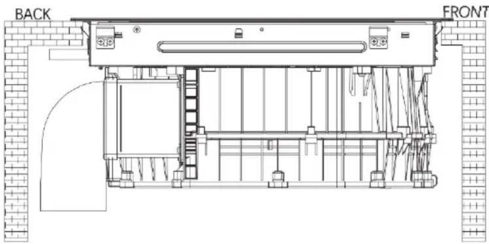
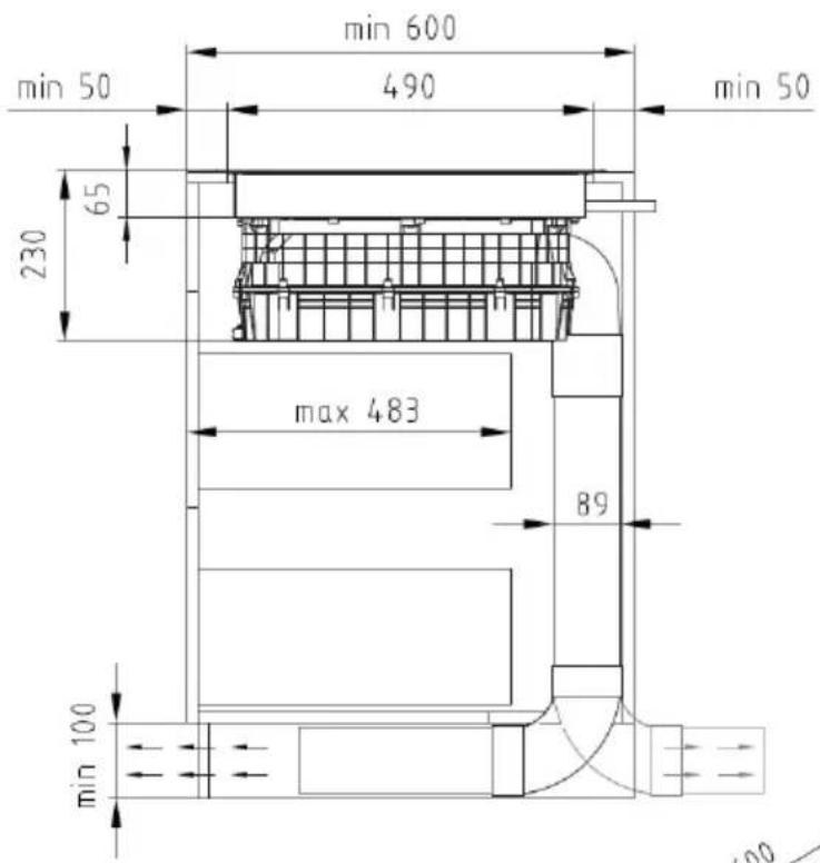
Figure 6 shows the dimensions for correct installation. Keep them in mind.
- Installation method A: the hob glass protrudes from the surface of the furniture. The cabinet opening requirements for installation are shown in Figure 7 (unit mm).
- Installation method B: the glass is completely level with the furniture. The cabinet opening requirements for installation are shown in Figure 8 (unit mm).
NOTE: if, during the installation of the hob it is necessary to replace the power cable of the appliance, you can turn the hob upside down and remove the screw in the position shown in figure 9 to replace it.
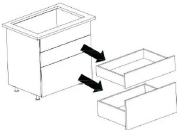
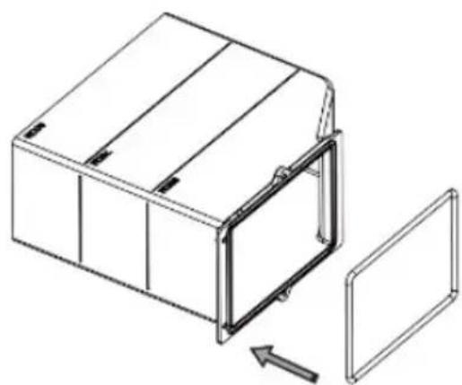
NOTE: before installing the appliance in the cabinet, it is necessary to remove the drawer(s) from the cabinet to facilitate installation (Fig. 10).
ENGLISH
Installing the baffles
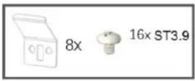
A total of 8 baffles are installed in the positions shown in figure 11.
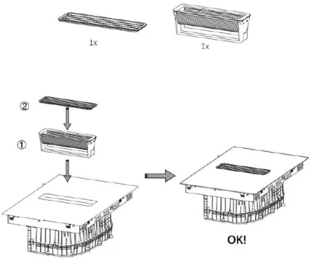
The steps for installing the grilles and filters in the appliance are shown in figure 12.
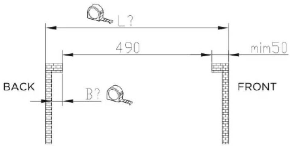
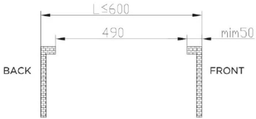
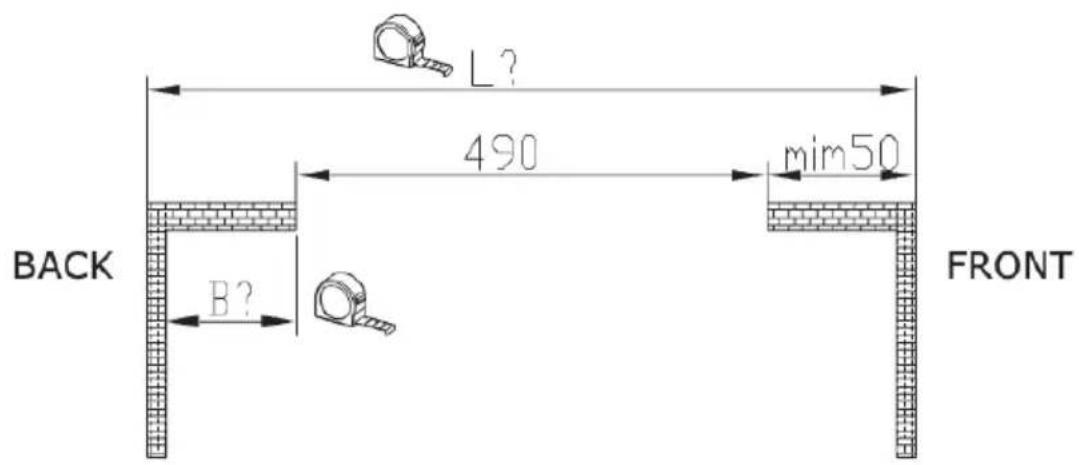
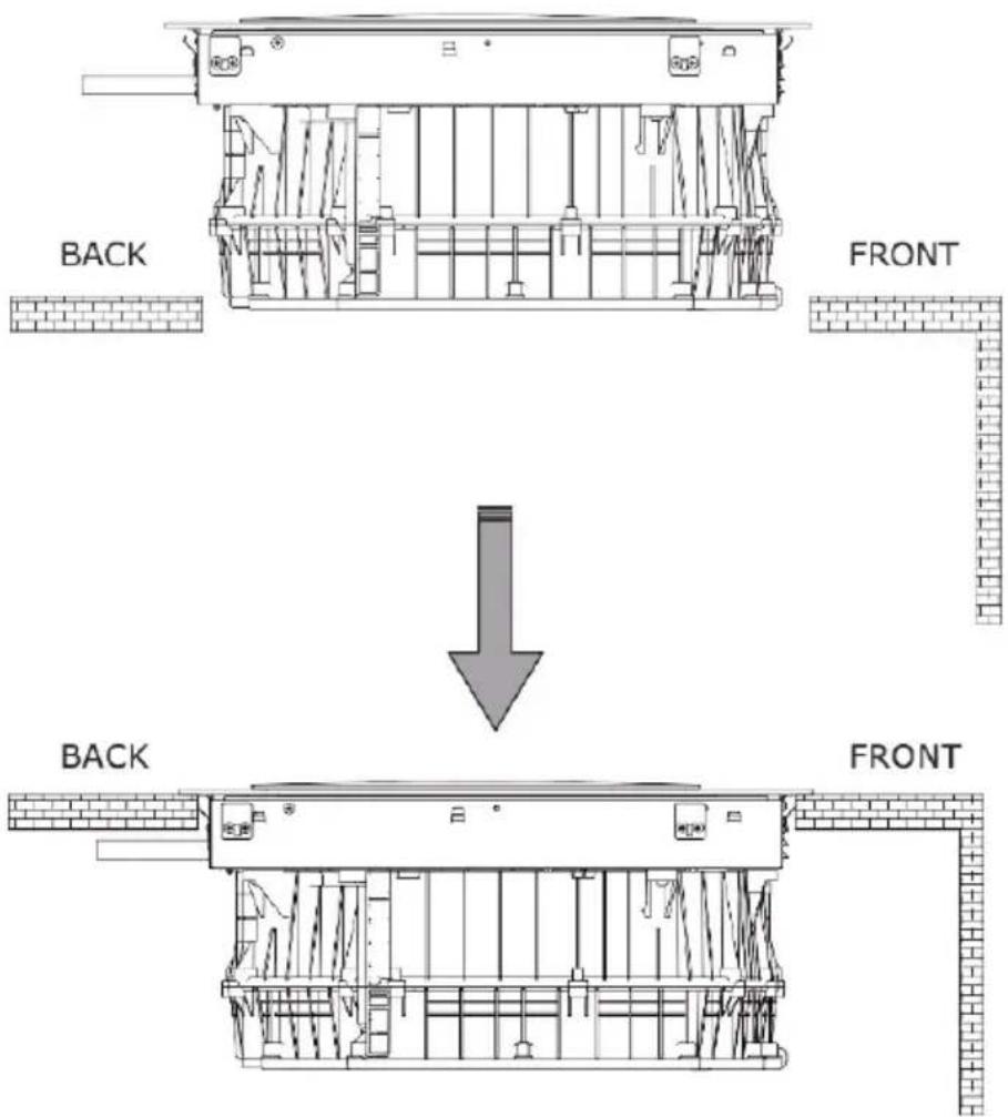
Depending on the overall width of the cabinet L, the installation is divided into two types. (Fig. 13)
A When L is less than or equal to 600 mm (Fig. 14)
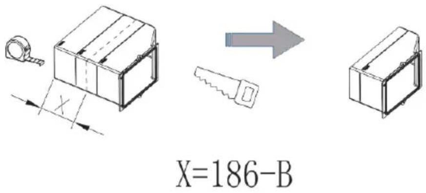
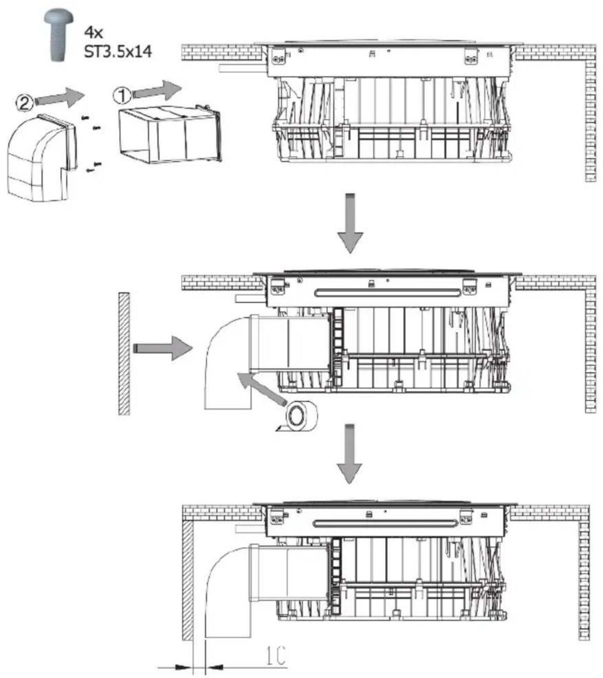
- When L is less than or equal to 600 mm, cut the pipe connector. The cut length is equal to 186 minus the length of B (Fig. 15).
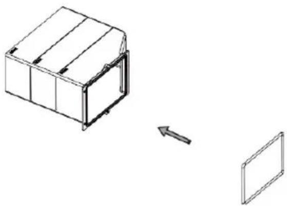
- After having proceeded with the cutting, install the sealing ring as shown in figure 16.
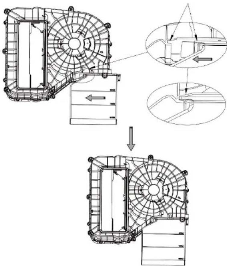
- Turn the appliance upside down and slide the pipe seal from the side into the appliance. (Fig. 17)
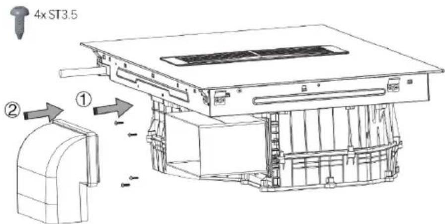
- Use four ST3.5 screws to secure the flue gasket, then install the 90 degree bend. (Fig. 18)
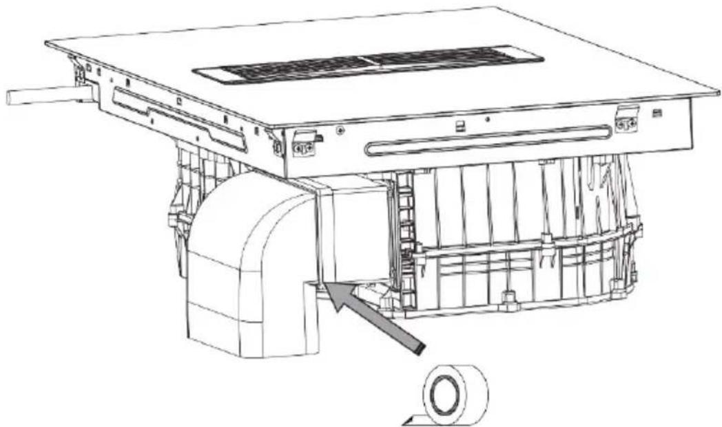
- Then, tape the gasket with adhesive tape. (Fig. 19)
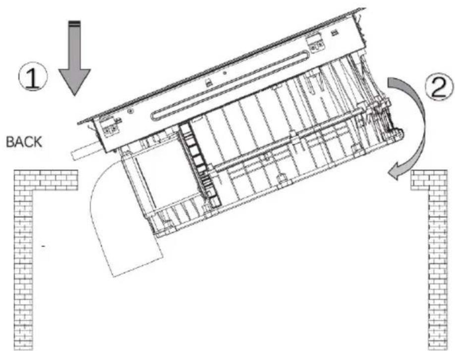
- As shown in figure 20 below, place the appliance in the cabinet diagonally.
- The installation is now complete. (Fig. 21)
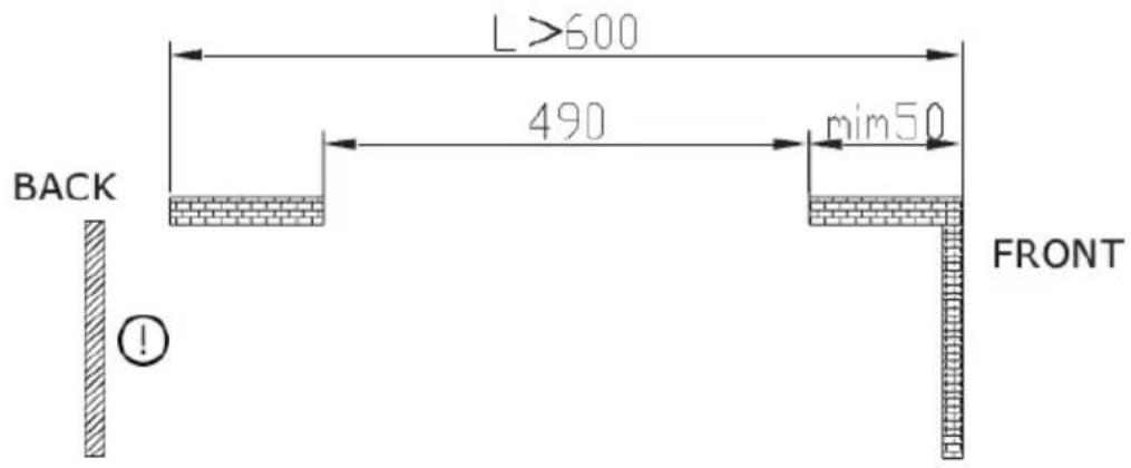
B When L is larger than 600 mm (Fig. 22)
- It is necessary to remove the rear of the cabinet to facilitate installation. (Fig. 23)
- Next, you must install the appliance in the cabinet as shown in figure 24.
- Then, install the rubber gaskets on the pipe. (Fig. 25)
- Install the flue as shown in picture 26 and fit the ST3.5x14 screws.
NOTE: remember to tape the gasket for a correct fit.

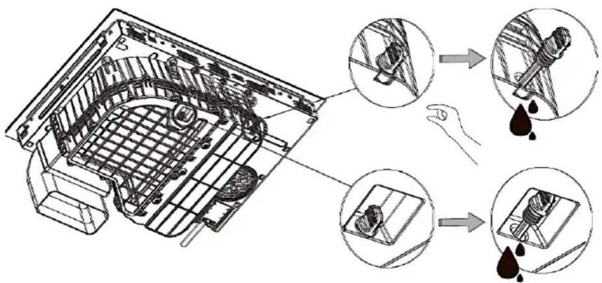
When it is necessary to drain water:
- Remove the rubber plug that is underneath the appliance, use a container to collect the water that comes out of it. (Fig. 27)
- Once the water has been drained or the appliance has been installed, press down firmly on the rubber plug to ensure proper sealing. (Fig. 28)
Installation accessories
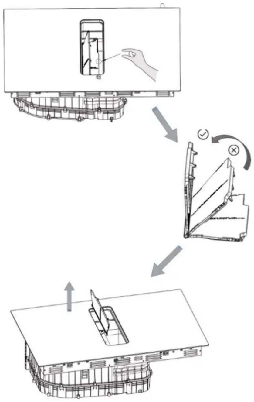
- Air extraction mode

- For air extraction mode, see figure 29. Open the filter cover 90 degrees, then remove the filter cover upwards for easy installation.
- Figure 30 shows the accessories required for assembly.
WARNING: for air extraction mode installation, it will not be necessary to install parts c and d.
Fig. 30 key
a. Grille
b. Grease filter
Make sure that the flue, cabinet, and cupboards purchased meet the following requirements, as shown in figure 31.
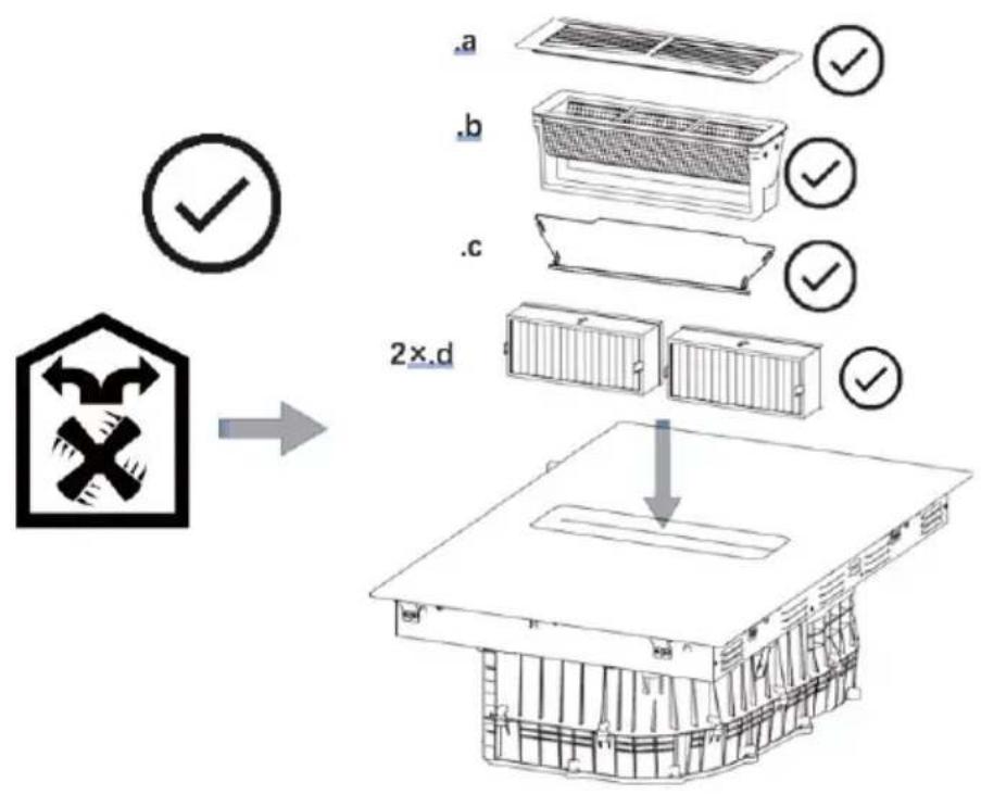
- Air recirculation mode

- Figure 32 shows the accessories required for assembly.
Fig. 32 key
a. Grille
b. Grease filter
c. Filter cover
d. Activated carbon filter
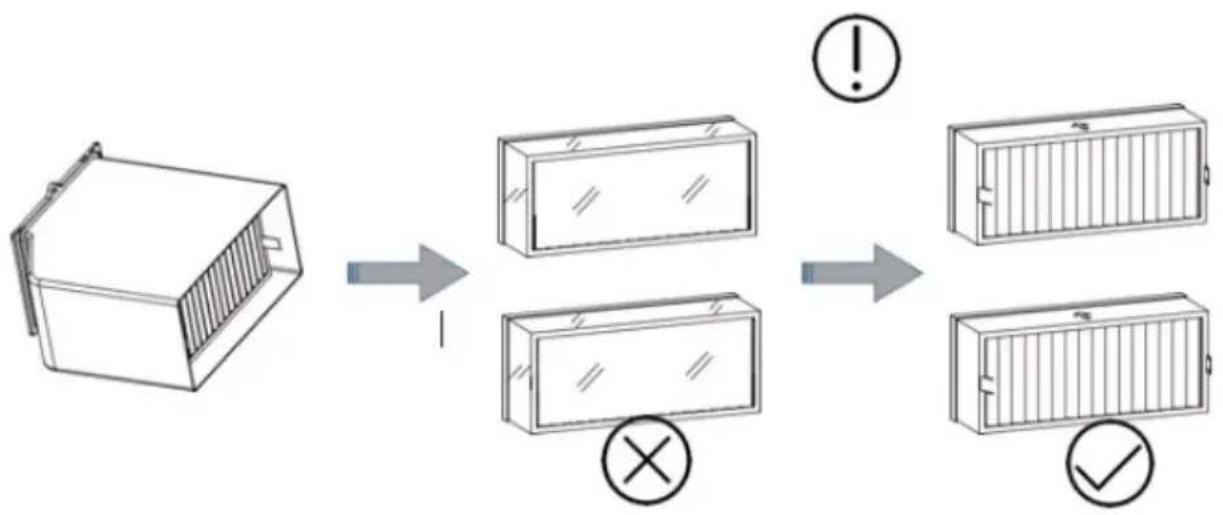
WARNING: before using the odour filter, remove the transparent film on the outside of the carbon filters. (Fig. 33)
To assemble it, follow the instructions below:
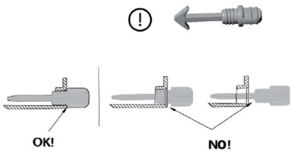
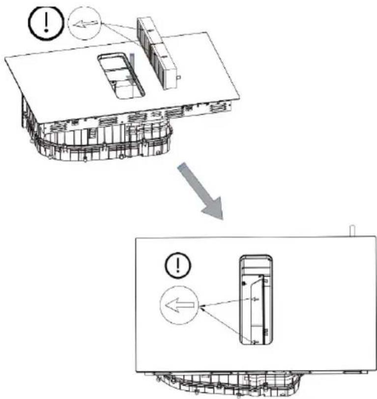
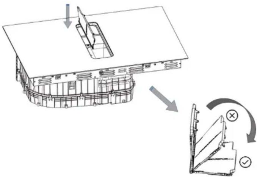
- Place the arrow on the filter cartridge facing left and then insert the filter cartridge into the insertion hole as shown in figure 34.
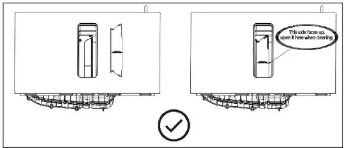
- Afterwards, install the filter cartridge cover vertically into the tab. Open the filter cover 90 degrees to completely cover the filter. (Fig. 35)
WARNING: the cover will pop off when pressed hard.
-
Press down to fit correctly. (Fig. 36)
-
Make sure that the cover is securely in place. (Fig. 37)
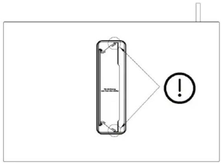
NOTE: the side shown in figure 38 should face upwards, open it when cleaning.
WARNING: ensure proper ventilation.
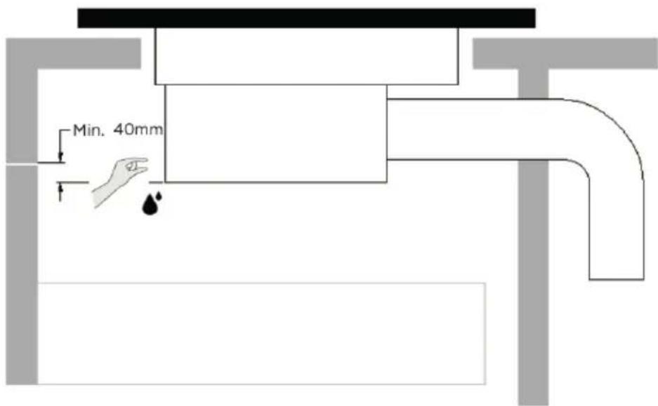
- A minimum distance of 40 mm must be maintained between the baffle and the bottom of the hob to allow liquids to drain away easily. Follow the recommendations below. (Fig. 39)
There are ventilation holes around the exterior of the hob. You must ensure these gaps are not blocked by the worktop when installing the hob. - Please note that the glue that binds the plastic or wooden material to the furniture must withstand a temperature of more than 150^ C to prevent the coating from peeling off.
- Therefore, the rear wall and the adjacent and surrounding surfaces must be able to withstand a temperature of 90^ C.
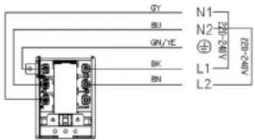
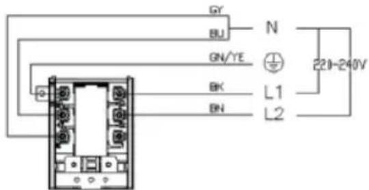
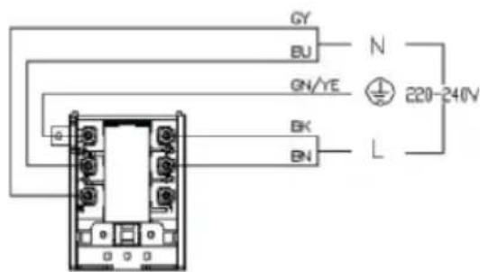
Connecting the hob to the mains. Fig. 40
The induction hob must be connected to the mains by a suitably qualified person.
Before connecting the hob to the mains, check that:
- Your home wiring system is suitable for the power consumption of the hob.
- The mains voltage matches the voltage stated on the rating label of the appliance.
- The power cable sections can withstand the load specified on the product rating label.
ENGLISH
- To connect the hob to the mains, do not use adapters, reducers, or branching devices, as they may cause overheating or fire.
- The power cable should not be in contact with any hot parts and must be positioned so as to avoid its temperature exceeding 75 °C.
- Check with an electrician whether your home wiring system is suitable without modifying it. Any modifications should only be carried out by a qualified electrician.
- If the total number of cooking zones of the appliance you have purchased is more than 4, you can connect it directly to the mains using a single-phase electrical connection.
- If the cable is damaged or needs to be replaced, avoid fixing it yourself and contact the official Cecotec Technical Support Service to avoid any accidents.
- If the appliance is connected directly to the mains, an omnipolar circuit breaker with an opening of at least 3 mm between the contacts must be installed.
- The person in charge of the installation must ensure that a correct electrical connection has been made and that it complies with current safety regulations.
- Do not bend or press the cable.
- The cable should be checked periodically. Only a qualified technician can replace it.

The bottom surface and the power cord of the hob should not be accessible after allation.
4. OPERATION
Operation instructions
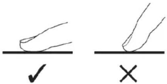
Touch icons
- The icons react to touch, so there is no need to apply any pressure.
- Use the base of your finger, not the tip. Fig. 41
- You will hear a beep every time the hob detects a finger.
- Make sure the icons are always clean and dry and that no objects (for example, a utensil or a cloth) are covering them. Even a thin layer of water can hinder the proper operation of the icons.
Choosing the right cookware
- Only use cookware with a base suitable for the induction hob.
- Look for the induction symbol on the packaging or at the bottom of the cookware.
- You can check if your cookware is suitable with a magnet test.
- Move a magnet towards the base of the cookware. If it sticks or is attracted by the utensil, this means that the utensil is compatible with the induction hob.
-
If you do not have a magnet:
-
Pour some water into the utensil to be tested.
-
If does not appear on the display flashing and water heats up, the cookware is suitable.
ENGLISH
- Cookware made of the following materials is not suitable: pure stainless steel, aluminium or copper without magnetic base, glass, wood, porcelain, ceramic, and earthenware.
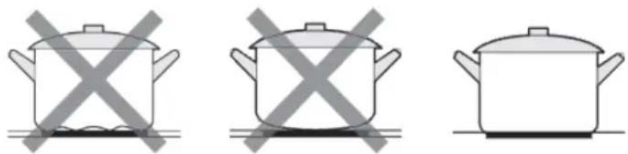
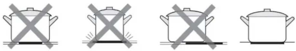
- Do not use cookware with serrated edges or with a curved base. Fig. 42
- Make sure the base of the cookware is smooth, flat against the glass, and of same size as the cooking zone. Use cookware whose diameter is the same as the selected cooking zone. The use of a slightly wider cookware will increase the efficiency of the energy used. If you use a smaller cookware, efficiency will be affected. The hob may not detect a cookware smaller than 140 mm.
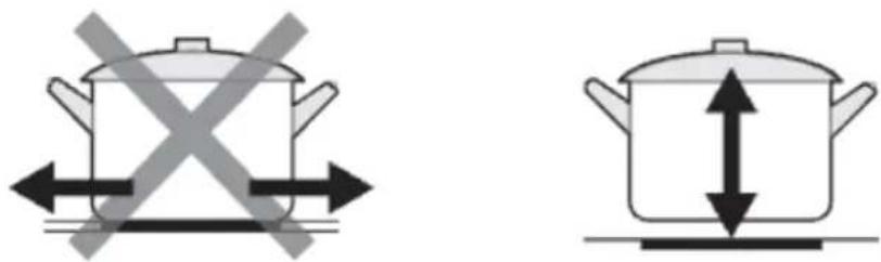
- Always place the cookware in the centre of the cooking zone. Fig. 43
- Always lift the cookware off the induction hob, do not slide it, as it could scratch the glass. Fig. 44
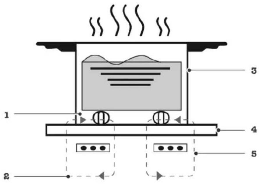
- Induction cooking is a safe, advanced, efficient and economical cooking technology. The induction hob works by electromagnetic vibrations that generate heat directly in the cookware, rather than indirectly by heating the surface of the glass. The glass heats up by itself because the cookware eventually heats it up. Fig. 45
Fig. 45 key
- Magnetic circuit
- Induced currents
- Cookware
- Glass ceramic hob
- Induction coil
You can use the kitchen hood in air extraction mode or in air recirculation mode.
Air extraction mode

- The air which is drawn in is cleaned by the grease filters and conveyed to the exterior by a pipe system.
- The air must not be discharged into a flue that is used for exhausting fumes from appliances burning gas or other fuels (not applicable to the appliances that only discharge the air back into the room).
NOTE:
If the exhaust air is to be conveyed into a non-operating smoke or exhaust gas flue, you must obtain the consent of the heating engineer responsible.
If the exhaust air is to convey through the external wall, a telescopic duct should be used.
Air recirculation mode

The air which is drawn in is cleaned by the grease filters and odour filter and conveyed back into the room.
ENGLISH
NOTE: to neutralise odours in this mode, an odour filter must be installed.
Setting the operating mode of the kitchen hood
The appliance is supplied with a pre-set air extraction mode. If you wish to switch from air extraction mode to air recirculation mode, follow the steps below:
- Adjust the hood settings.
Note: the lock function has to be deactivated.
- Press the A icon for 3 seconds. The display will show "ou" and "In" and a beep will sound. Use the Lock icon to change the mode.
- If the hood is in the air extraction mode, the display will show "ou". Press the power icon to confirm the setting and switch the kitchen hood on.
- If the hood is in the air recirculation mode, the display will show "In". Press the power icon to confirm the setting and switch the kitchen hood on.
Quick start guide
NOTE: be careful when frying, as oil and fat heat up very quickly, especially if you use the Boost function. At extremely high temperatures, oil and grease can burn, posing a serious fire hazard.
Cooking advice
- When food starts boiling, reduce the power.
- Using a lid will reduce the cooking time and save energy due to heat retention.
- Reduce the amount of liquid or grease to shorten cooking times.
- Start cooking with a high power setting and reduce it as food heats up.
Simmering and cooking rice
- Simmering occurs below the boiling point, at about 85°C, when some bubbles rise to the surface of the cooking liquid. It is essential for preparing delicious soups and tender stews because it enhances the flavours without overcooking the food. Egg-based and flour-thickened sauces should also be cooked below boiling point.
- Some recipes, like cooking rice using the absorption method, may require a setting higher than the lowest setting to ensure that the food is cooked properly in the recommended time.
Pork chops
For juicy and tasty results:
- Leave the meat at room temperature for about 20 minutes before cooking it.
- Preheat a heavy-based frying pan.
- Brush both sides of the meat with oil. Spray a small amount of oil in the hot frying pan and place the meat.
- Turn the meat only once during cooking. The exact cooking time will depend on the meat
thickness and your likings. Times may vary from 2 to 8 minutes per side. Press the meat to measure the cooking degree; the firmer it is, the more cooked it is.
- Let the steak stand on a hot dish for some minutes to prevent it from going soft before serving.
Stir-frying
- Choose a flat-bottomed wok compatible with the induction hob or a large frying pan.
- Have all ingredients ready. Stir-frying is fast. If you cook large amounts, cook food in several smaller batches.
- Preheat the cookware briefly and add two tablespoons of oil.
- Cook meat first, set it aside and keep it warm.
- Stir-fry vegetables. When vegetables are hot but still crunchy, choose a lower power for the cooking zone, place the meat in the frying pan again and add a sauce.
- Gently stir the ingredients to heat through.
- Serve them immediately.
Detection of small objects
If you place an unsuitably sized or non-magnetic cookware (e.g., aluminium) or any other small object (e.g., knife, fork, key) on the induction hob, the latter will automatically enter standby mode within 1 minute. The fan will continue working for 1 more minute.
Power setting
The following settings are for guidance only. The exact setting will depend on different factors, such as cookware and the amount of food to be cooked. Test the induction hob to find the settings that suit you best.
| Power setting | Suitable for |
| 1-2 | - lightly heating small amounts of food- melting chocolate, butter, and food that burns quickly- simmering- gradually heating |
| 3-5 | - reheating- quickly cooking- cooking rice |
| 6-11 | - crepes/omelettes |
| 12-13 | - frying- cooking pasta |
ENGLISH
| Power setting | Suitable for |
| 15/P | - stir-frying at a higher temperature- boiling- boiling soup- boiling water |
Start cooking
- Press and hold the power icon ⏻ for 3 seconds. After switch-on, you will hear a beep and the control panel will display “-” to indicate that the appliance has entered standby mode.
- Place a suitable cookware on the cooking zone you wish to use. Make sure the bottom of the cookware and the cooking zone surface are clean and dry.
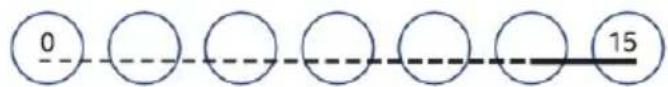
- Select a power level by sliding your finger on the slider control (Fig. 46).
NOTE: you can change the power setting at any time during cooking.
-
If the = symbol and the number of the selected power flash alternately on the display, it means that:
-
you have not placed the cookware on the correct cooking zone;
- the cookware you are using is not suitable for the induction hob;
- the cookware is too small or is not correctly centred on the cooking zone.
NOTE: if there is no suitable cookware in the cooking zone, no heat will be produced.
- The display will automatically switch off after 1 minute if no cookware is placed on the hob.
Manual control of the kitchen hood
You can control the power of the kitchen hood manually.
NOTE: the use of tall cookware may prevent the extraction system from working properly. You can increase the extraction power by placing the lid of the cookware at an angle.
- To activate the manual control of the hood, when the appliance is switched on (not in standby mode), press to activate the hood.
- Press again to choose the desired power (0-3). Press and hold for 3 seconds to switch off the hood.
- Press the Boost function icon to activate it.
Switching off the kitchen hood
- Press the power icon to switch off the kitchen hood (the hob will also be off).
- Use until power level 0 is selected.
NOTE: switch off the cooking zone by sliding your finger towards number 0 (Fig. 47). Make sure the display shows "0". - Switch the induction hob off by pressing the power icon.
Switching on the kitchen hood
- The kitchen hood has two modes: manual and automatic.
- The manual mode can be activated when the hob is on. It will be automatically deactivated two minutes after the hob is switched off.
Manual mode
When the hob is on, press ✿ or >>. The display will show the selected power level (0-3) or the letter "b".
Automatic mode
- When the hob is on, press will be shown on the display.
- The hood will be switched off:
- 2 minutes after switching off the cooking zones
○ If you press the power icon (1)
Using the Boost function
Activating the Boost function
Press MAX
NOTE: make sure that the display shows the Boost function symbol.
Deactivating the Boost function
- Press the slider control of the cooking zone in which you want to deactivate the Boost function (Fig. 48).
- Switch the induction hob off by pressing the power icon ⏻
NOTES:
- This function can be activated in any cooking zone.
- The cooking zone will return to the original setting after 10 minutes.
- If the original power setting is 0, it will return to full power after 10 minutes.
- If the Boost function is enabled in one of the cooking zones and you also activate it in another zone, both zones will operate at power level 15 (the Boost function will be deactivated).
Operating the kitchen hood at full power
- The kitchen hood has a maximum power level.
-
Select the maximum power level by pressing.
-
"b" will be shown on the display.
-
To deactivate the maximum power level, use ✿ to select the desired power level or to switch off the hood (by selecting level 0).
ENGLISH
Flex zone
The flex zone can be used as a single cooking zone or as two separate cooking zones, depending on your cooking needs.
The flex zone consists of two independent inductors that can be controlled separately. When operating as a single zone, the part on which no cookware is placed will automatically switch off after 8 seconds.
To ensure correct detection and even heat distribution, the cookware must be positioned:
- At the front or rear of the flexible zone, if the cookware is less than 21 cm long.
- Anywhere, if the cookware is larger than 21 cm.
Using the flexible zone as an individual cooking zone
- Press the corresponding icon to use the flexible zone as an individual cooking zone.
- The power of this zone is adjusted in the same way as the other zones.
- If you wish to add another cookware press the corresponding icons again so that the zone detects it.
Using the flexible zone as two separate cooking zones
Press the flexible zone icon in order to use the flexible zone as two separate cooking zones with different power settings.
Locking the icons
- You can lock the icons to avoid any unintentional use (e.g. children accidentally turning on the cooking zones).
- When you activate the lock, all the icons will be disabled, except for the power icon.
- Press and hold the Lock icon for 3 seconds to enable the lock function. "Lo" will appear on the display.
- Press and hold the Lock icon for 3 seconds to deactivate the lock function.
When the hob is locked, all icons are disabled except for the power icon. In case of an emergency, you can switch the hob off with the power icon. However, to perform any other operation, you must unlock the hob.
Power management function
- On the induction hob, you can set a maximum power consumption level. Different levels of energy consumption are available.
- The induction hob is capable of self-limiting itself to consume less energy and thus avoid the risk of overloading.
Activating the power management function
Note: the lock function has to be deactivated.
-
Press and hold the icon of the right cooking zone for 3 seconds (you will hear a beep).
-
Press and hold the icon of the left cooking zone for 3 seconds (you will hear a beep).
Selecting a different energy consumption level
- Select the desired power consumption level with the Lock function icon (the power consumption level is based on the hob specifications).
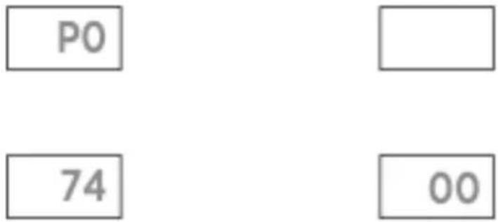
Energy consumption levels
Fig. 49
- There are 5 selectable power levels, from 2.8 kW up to 7.4 kW.
- The left and right zone displays will show the one you have selected.
"28 00": the maximum power consumption is 2.8 kW.
"35 00": the maximum power consumption is 3.5 kW.
"45 00": the maximum power consumption is 4.5 kW.
"58 00": the maximum power consumption is 5.8 kW.
"74 00": the maximum power consumption is 7.4 kW.
Confirmation of the energy consumption level
After choosing a maximum power consumption level, press the power icon to confirm the selection. The hob will switch off.
Timer
- You can set it so one or both cooking zones turn off once the time expires.
- The default maximum timer time will depend on the selected power level.
Setting the timer to switch off a cooking zone
- Slide your finger across the cooking zone slider control. Fig. 50
- Adjust the time by pressing the - or + icons. Press the + or - icons once to increase or decrease the time in 1-minute intervals.
- Press and hold the + or - icons to increase or decrease the time in 10-minute intervals.
- Once the timer is set, the countdown will start immediately. The display will show the remaining time.
- When the countdown ends, the corresponding cooking zone will turn off automatically.
Setting the timer in more than one zone
- The steps for setting the timer on more zones are similar to those for setting a single zone.
- The timer setting for each cooking zone is set and displayed independently.
ENGLISH
Deactivating the timer
- To deactivate the timer, you must set the cooking zone time to 0:00.
- Another option is to press and hold the - and + icons for 1 second.
Please note
- The manual timer setting may not exceed the default time of the selected power in the cooking zone. If the power of the cooking zone is reduced after the maximum allowed timer time has been set, it will automatically change to the maximum time of the newly selected power.
- When the timer time is shown on the display, you can press once on the slider control to show the selected power level on the display. At this point, you can press the slider control again or slide your finger over it to select the desired power level.
Default operating time
- The induction hob and the kitchen hood feature an automatic protection shutdown function.
- The hob and the hood switch off automatically if you forget to switch them off.
- The default operating times for the different power levels are shown in the table below:
Induction hob
| Power level 123456789 | |||||||||
| Default operating time (minutes) | 480 | 480 | 480 | 360 | 360 | 360 | 240 | 240 | 240 |
| Power level | 10 | 11 | 12 | 13 | 14 | 15 | |||
| Default operating time (minutes) | 120 | 12012090 | 12090 | 90 | 90 |
Kitchen hood
| Power level | 1 | 2 | 3 |
| Default operating time (minutes) | 480 | 240 | 120 |

Users with a pacemaker should seek medical advice before using this hob.
5. CLEANING AND MAINTENANCE
Cleaning the hob
| Soiling type How to | clean it Important | |
| Usual dirt on glass (fingerprints, marks, food stains, etc.) | Unplug the hob from the mains. Use a hob cleaner while the glass is still tempered (but not hot). Rinse the appliance and dry the glass with a clean cloth or paper towel. Unplug the hob from the mains. | If you unplug the hob from the mains, the hot surface indicator light will disappear, but the cooking zone will still be hot. Be especially careful.Abrasive cloths, some nylon scouring pads and strong cleaning products can scratch the glass. Always read the label to check the suitability of the cleaning product or scouring pad you are using.Never leave cleaning product residues on the induction hob; the glass may become stained. |
| Hot sugar spills on the glass | Remove them immediately with a spatula or a suitable scraper for induction hobs but be careful with the hot surfaces of the cooking zone.Unplug the hob from the mains.Hold the scraper at an angle of 30° and drag the dirt onto a cool area of the hob.Wipe up the spillage with a cloth or paper towel.Follow steps 2 to 4 in the section "Usual dirt on glass". | Remove melted sugary food stains or spills as soon as possible. If left to cool on the glass, they may be difficult to remove or may even permanently damage the surface of the hob.Cutting hazard: the blade of the scraper may be very sharp, be careful when removing the guard.Use it with extreme care and always store it safely and out of the reach of children. |
| Spills on icons | Unplug the hob from the mains.Clean up the spillage.Clean the icons area with a sponge or a damp and clean cloth.Dry the area completely with a paper towel.Unplug the hob from the mains. | The induction hob may beep and switch off, and the icons may not work if wet. Be sure to dry the icons before switching the hob back on. |
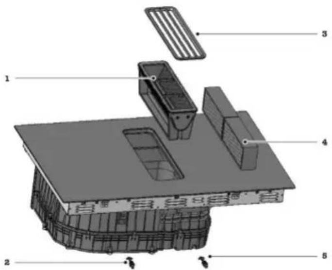
Parts to be cleaned or replaced
Figure 51 shows the components of the appliance that are replaced or cleaned.
Fig. 51 key
- Grease filter
- Rubber plug
- Grille
- Odour filter
- Rubber plug
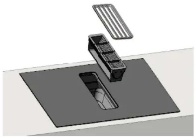
Replacing the odour filter
Replace the odour filter on a regular basis. To do so, follow these steps:
- Remove the grille and the grease filter. Fig. 52
- Clean them properly.
NOTE:
- Grease can accumulate at the bottom of the filter.
- Keep the grease filter horizontal to prevent it from dripping.
ATTENTION:
- Only use original replacement filters.
- Falling grease filter and grille can damage the hob.
-
Odour filters are available from specialised dealers.
-
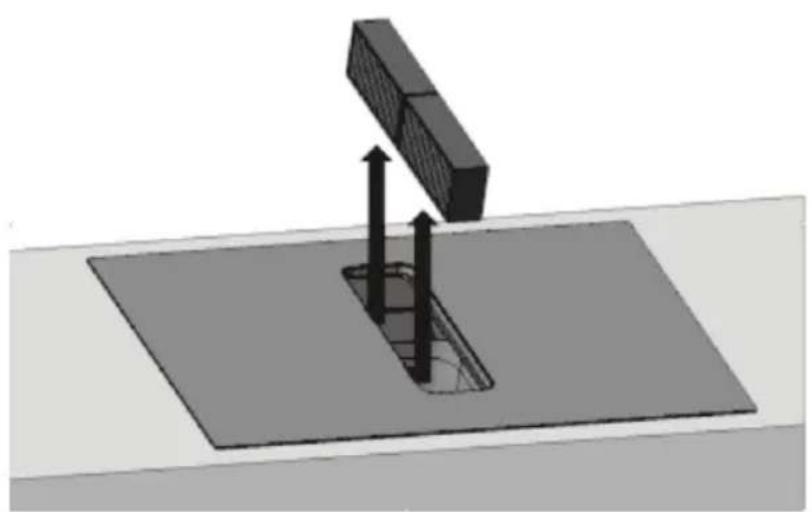
Remove the two odour filters and dispose of them properly. Fig. 53
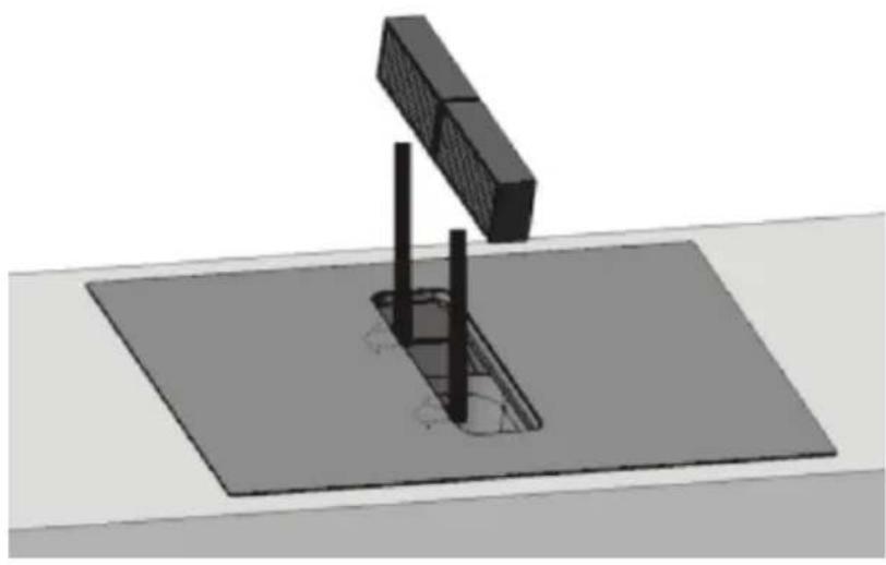
- Insert two new odour filters on the left side of the appliance. Fig. 54
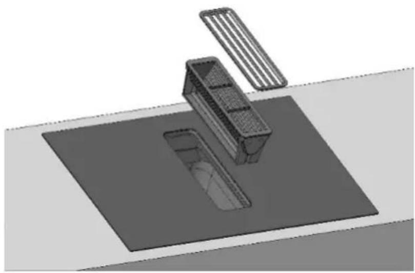
- Insert the grease filter and fit the grille. Fig. 55
Resetting the saturation indicator
- Replace the odour filter.
-
When the hob is switched off, press, and hold the Lock function icon ⏻ for 3 seconds to lock the hob.
-
Press and hold ✿ for 3 seconds to reset the odour filters. The hood display will show "CL".
Cleaning of the grille and grease filter
- The grease filter retains the grease contained in the cooking vapours. To keep it in good condition, it should be cleaned regularly.
- WARNING: Risk of fire.
- Grease deposits in the filters can catch fire.
- Never use the appliance without the grease filter.
- Clean the grease filter regularly.
- Do not create naked flames in the vicinity of the appliance when in use (e.g. when flambéing).
- Do not install the appliance near a heating appliance that uses solid fuels (e.g. wood or coal) unless the appliance has a sealed, non-removable cover. No sparks should fly.
ATTENTION
- Falling grease filter and grille can damage the hob. (It is recommended to clean the grease filter every 7 days).
- Remove the grille and grease filter and clean them properly.
-
Grease can accumulate at the bottom of the filter. Keep the grease filter horizontal to prevent it from dripping.
-
Clean the grille.
- Clean the grease filter.
- If necessary, remove the odour filters or sound insulation filters and clean the inside of the appliance.
- If there are any foreign objects inside the appliance, remove them and make sure that no parts are blocked.
- Clean the inside and outside of the appliance with a soft cloth dampened with soapy water.
- Once cleaning is complete, be sure to put the grease filter back in place after it has dried properly.
Cleaning the grease filter or grille manually
- Immerse the grease filter or grille in hot soapy water.
- Use a brush to clean the filter or grille.
- Thoroughly rinse the grease filter.
- Allow the grease filter to dry thoroughly.
WARNING: do not use abrasive, acidic or alkaline cleaning products. If the grease does not disappear, use a special grease solvent.
ENGLISH
Cleaning the grease filter in the dishwasher
- Place the grease filter loosely in the dishwasher.
NOTE: if the grease filter is too dirty, do not use any tools to clean it. Do not use abrasive, acidic, or alkaline cleaning products.
- Switch on the dishwasher.
NOTE: select a temperature below 70 °C.
- Allow the grease filter to dry completely before replacing it after it has been cleaned in the dishwasher.
Cleaning the inside of the appliance
-
Drain any liquids that enter the appliance using the rubber plug. Before doing so, make sure that the hob is cool and that the residual heat indicator light has disappeared.
-
Remove the rubber plug with one hand and a container with the other hand, empty any liquids or objects that may be inside the appliance.
-
Make sure that the rubber plug is not blocked before putting it back in place.
-
Remove any objects that have entered the appliance once it has cooled down. To do this, remove the grease filter.
6. TROUBLESHOOTING
After prolonged use, the appliance may experience some errors or malfunctions. The following tables contain possible causes of the problem and solutions to solve it.
| Problem Possible causes Possible solution | |
| The induction hob does not switch on | No power supply. Make sure the hob is connected to the mains and it is on.Check if there has been a power failure. After these checks, if the problem persists, please contact the official Cecotec Technical Support Service. |
| Icons do not respond | Icons are locked. Unlock the icons. |
| It is difficult to use the icons | There may be a slight film of water on the icons, or you may be using your fingertip to press the icons. | Make sure the icons are dry and press them with the base of your finger. |
| The glass is damaged | You have used cookware with rough bases.You have used inappropriate and abrasive scouring pads or cleaning products. | Use cookware with flat and smooth bases. |
| Some cookware emits crackling or popping noises | This may be due to the composition of your cookware (layers of different metals that vibrate differently). | This is normal for some cookware and does not indicate a fault. |
| The induction hob makes a slight buzzing sound when used at high power | This is due to the induction cooking technology. | It is usual, but the noise should decrease or completely disappear by lowering the power setting. |
| Fan noise is heard coming from the induction hob | A cooling fan built in in this induction hob has been activated to prevent overheating of the electronic components. It may still operate even after turning off the induction hob. | This is normal and there is no need to worry. Do not unplug the hob from the mains if the fan is still running. |
| Cookware does not heat up and does not appear on the display | The induction hob does not detect the cookware because it is not suitable for induction cooking.The induction hob does not detect the cookware because it is too small for the cooking zone or is not centred in it. | Only use cookware compatible with the induction hob.Centre the cookware and make sure its base matches the size of the cooking zone. |
ENGLISH
| The induction hob or one of the cooking zones has turned off unexpectedly, emits a sound, and an error code is displayed (usually alternating with one or two digits on the cooking timer display) | Technical fault. Write down the | letters and numbers of the error, unplug the induction hob from the mains, and contact the official Cecotec Technical Support Service. |
The induction hob is fitted with a self-diagnostic function. With this function, the technician can check the operation of different components without de-installing the induction hob from the worktop.
| Problem | Possible causes Possible solution | |
| E1, E2, E7 | Fault of the temperature sensor. | Contact the official Cecotec Technical Support Service. |
| E3, E4 | Fault in the temperature sensor of the IGBT transistor. | Contact the official Cecotec Technical Support Service. |
| EU The connection between the display board and the main board fails. | Contact the official Cecotec Technical Support Service. | |
| EL, EH | Abnormal supply voltage. | Check if the power supply operates correctly. After making sure that the power supply is normal, reconnect the hob. |
| C1 The temperature of the induction hob sensor is too high. | Let the hob cool down and restart it. | |
| C2 IGBT transistor sensor temperature is too high. | Let the induction hob cool down and restart it. | |
| F5 Cooling | fan failure. Let the induction hob | cool down and restart it. |
| B3 The temperature of the kitchen hood is abnormal. | Allow the motor to cool down and restart the hood. |
| B5 Failure to start the kitchen hood. | Check the hood for foreign objects and restart it. |
| B7 Failure to start the kitchen hood. | Contact the official Cecotec Technical Support Service. |
| Bd Failure in communication between the display board and the hood controller board. | Contact the official Cecotec Technical Support Service. |
| EF You have pressed several icons at the same time. | Clean the control panel. |
| FC Need to replace the filter. Change the filter. |
Error codes and possible solutions
| Error code | Problem Solution | |
| EL,EH | The voltage of the power supply is higher than the rated voltage. | Check if the power supply operates correctly.After making sure that the power supply is normal, reconnect the hob. |
| C1 | The temperature of the induction hob sensor is too high. | Wait for the hob temperature to return to normal.Press the power icon to restart the hob. |
| C2 | IGBT transistor sensor temperature is too high. | Wait for the transistor temperature to return to normal.Press the power icon to restart the hood. Check if the fan is working properly, if not, replace it. |
| B3 | The voltage on the hood controller board is abnormal. | Press the power icon to restart the hood. |
ENGLISH
| B7 | The air duct of the ventilation system is completely obstructed. | Press the power icon to restart the hood. Check the hood for foreign objects and restart it. |
| E2 | Fault in the temperature sensor of the glass ceramic hob (short-circuit). | Check the connection or replace the temperature sensor on the glass ceramic hob. |
| E1 | Fault in the temperature sensor of the glass ceramic hob (open circuit). | |
| E7 | Fault in the temperature sensor of the glass ceramic hob (not valid). | |
| E4 | IGBT transistor temperature sensor failure (short circuit). | Replace the power board. |
| E3 | IGBT transistor temperature sensor failure (open circuit). | |
| B5 Error in the ventilation system. | Replace the control board or the hood motor. | |
| Bd | Failure in communication between the display board and the hood controller board. | Replace the hood controller, power supply board or display board, and check the connection cable for damage. |
| Fault Problem Solution A Solution B | |||
| The LED indicator lights do not light up when the hob is plugged in. | There is no electricity. | Check if the plug is properly connected to the mains and if the latter works. | |
| The auxiliary power board and the board connected to the display malfunction. | Check the connections. | ||
| The auxiliary power board is damaged. | Replace the power board. | ||
| The display is damaged. | Replace the display board. | ||
| Some icons do not respond, or the LED display does not work normally. | The display is damaged. | Replace the display board. | |
| The cooking power indicator light turns on, but the hob does not heat up. | High temperature of the cooking hob. | The room temperature may be high. The air inlet or outlet may be blocked. | |
| The fan is faulty. | Check if the fan is working properly, if not, replace it. | ||
| The power board is damaged. | Replace the power board. | ||
| The hob suddenly stops heating and the "u" symbol flashes on the display. | The cookware used is not suitable. | Use a suitable cookware. | The cookware detection circuit is damaged, replace the power supply board. |
| The cookware diameter is too small. | |||
| The hob has overheated. | Wait for the hob temperature to return to normal. Press the power icon to restart the hob. | ||
| When trying to heat zones of the same size, the display shows "u". | The power board and the board connected to the display malfunction. | Check the connections. | |
| The display board of the communication unit is damaged. | Replace the display board. | ||
| The main board is damaged. | Replace the power board. | ||
| The fan motor produces unusual noises. | The motor fan is damaged. | Replace the fan. |
Refer to these instructions to repair common faults.
ENGLISH
Do not try to disassemble the appliance on your own to avoid hazards and damages to the induction hob.
7. TECHNICAL SPECIFICATIONS
Product reference: A01_EU01_100088
Product: Bolero Squad IH 4800 TotalFlex80
Total power: 7400 W
Kitchen hood power: 160 W
Rated voltage: 220-240 / 380-415 V 3N
Rated frequency: 50/60 Hz
A:2200 W/3600 W(B)
B:2200 W/3600 W(B)
C:2200 W/3600 W(B)
D:2200 W/3600 W(B)
| Symbol | Value Unit | ||
| Model reference A01_EU01_100088 | |||
| Annual energy consumption | AEC_hood | 29.9 kWh/a | |
| Time increment factor | f | 1.0 | |
| Fluid dynamic efficiency | FDE_hood | 28.4 | |
| Energy Efficiency Index (EEIW) | EEI_hood | 49.5 | |
| Measured airflow at maximum efficiency point | Q_BEP | 29.1 m | ^3/h |
| Air pressure measured at maximum efficiency point | P_BEP | 287 Pa | |
| Maximum airflow (Highest setting) | Q_max | 543.8 m | ^3/h |
| Maximum airflow (Boost function) | Q_max | 636.4 m | ^3/h |
| Electrical input power measured at maximum efficiency point | W_BEP | 82 | W |
| Nominal power of the lighting system | W_L | N/A W | |
| Measured illumination of the illumination system on the cooking surface | E_med | N/A lux | |
| Standby power consumption | P_s | N/A W | |
| Power consumption in off mode | PO | 0.42 W | |
| Noise level (Boost function) | L_WA | 70 dB | |
| Noise level (Highest setting) | L_WA | 65 dB | |
| Noise level (Lowest setting) | L_WA | 57 dB |
| Symbol Value Unit | |||
| Model reference A01_EU01_100088 | |||
| Type of cooking hob Electric hob | |||
| Number of hotplates and/or cooking zones 2 zones | |||
| Heating technology (induction hotplates and cooking areas, radiation hotplates, solid hotplates) | Cooking zones | ||
| Symbol Value Unit | |||
| For circular lamps or cooking areas: diameter of the usable area of each electric cooking spot, rounded to the nearest 5 mm | ∅ | Left zone:37.5 x 20.5Right zone:37.5 x 20.5 | cm |
| For non-circular lamps or cooking areas: width and length of the usable surface of each lamp or electric cooking area, rounded to the nearest 5 mm | LW | N/AN/A | cm |
| Energy consumption per lamp or cooking area, calculated per kg (*) | EC_electric cooking | Left zone:179.6Right zone:182.3 | Wh/kg |
| Energy consumption of the hob, calculated per kg (*) EC | electric hob | 181.0 Wh/kg | |
ENGLISH
The appliance power consumption when off is 0.42 W, following the guidelines of EN 50564:2011 and the European regulations 1275/2008/EC and 801/2013/EC. For this purpose, the appliance is connected to the mains without performing any function. The switch/knob of the appliance was set to the Off position.
Regulation (EU) 66/2014
Technical specifications may change without prior notification to improve product quality. Made in China | Designed in Spain
8. DISPOSAL OF OLD ELECTRICAL AND ELECTRONIC APPLIANCES
This symbol indicates that, according to the applicable regulations, the product and/or batteries must be disposed of separately from household waste. When this product reaches the end of its shelf life, you should dispose of the cells/batteries/accumulators and take them to a collection point designated by the local authorities.
Consumers must contact their local authorities or retailer for information concerning the correct disposal of old appliances and/or their batteries.
Compliance with the above guidelines will help protecting the environment.
9. TECHNICAL SUPPORT AND WARRANTY
Cecotec shall be liable to the end user or consumer for any lack of conformity that exists at the time of delivery of the product under the terms, conditions, and deadlines established by the applicable regulations.
It is recommended that repairs be carried out by qualified personnel.
If at any moment you detect any problem with your product or have any doubt, do not hesitate to contact the official Cecotec Technical Support Service at +34 963 210 728.
10. COPYRIGHT
The intellectual property rights over the texts in this manual belong to CECOTEC INNOVACIONES, S.L. All rights reserved. The contents of this publication may not, in whole or in part, be reproduced, stored in a retrieval system, transmitted, or distributed by any means (electronic, mechanical, photocopying, recording or similar) without the prior authorization of CECOTEC INNOVACIONES, S.L.
1. PIÈCES ET COMPOSANTS
Image 1
3. INSTALLATION DU PRODUIT
A: 2200 W/3600 W (B)
B: 2200 W/3600 W (B)
C: 2200 W/3600 W (B)
D: 2200 W/3600 W (B)
natural_image
Technical line drawing of an electronic device casing with internal components and mounting hardware (no text or symbols)Fig./Img./Abb./Afb./Rys. 9
natural_image
Line drawing of a three'-enclosed drawer with arrows indicating folding or assembly (no text or symbols)OK!
natural_image
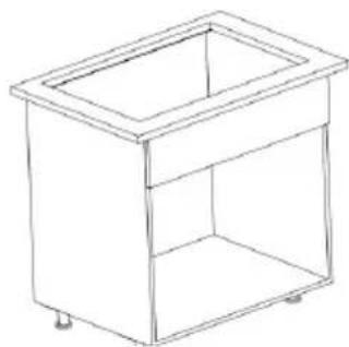
Line drawing of a rectangular box with a lid, no text or symbols presentFig./Img./Abb./Afb./Rys. 10
text_image
8x 16x ST3.9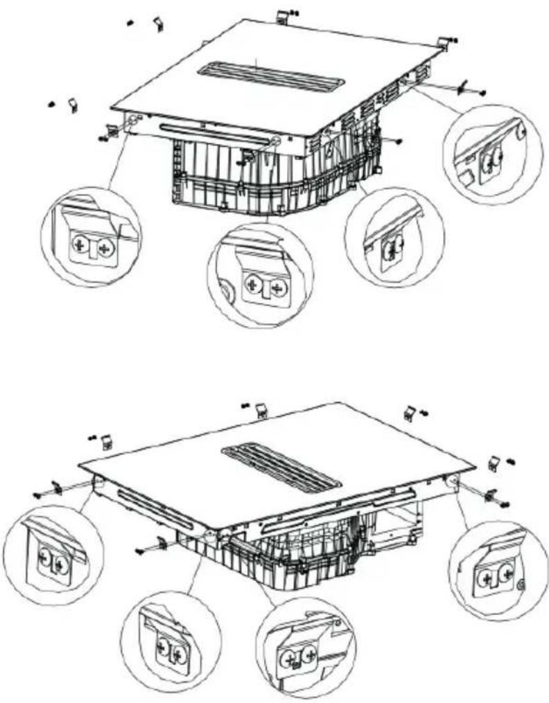
text_image
Technical diagram of an electric vehicle battery pack with labeled components and exploded viewsFig./Img./Abb./Afb./Rys. 11
flowchart
graph TD
    A["1x"] --> B["①"]
    B --> C["②"]
    C --> D["1x"]
    D --> E["OK!"]
Fig./Img./Abb./Afb./Rys. 12
text_image
L? 490 mim50 BACK B? FRONTFig./Img./Abb./Afb./Rys. 13
① S1:L≤600
text_image
L≤600 490 mim50 BACK FRONTFig./Img./Abb./Afb./Rys. 14
text_image
X=186-BFig./Img./Abb./Afb./Rys. 15
natural_image
Diagram showing a 3D box-like structure transforming into a separate rectangular frame, with an arrow indicating transformation (no text or symbols present)Fig./Img./Abb./Afb./Rys. 16
text_image
Technical diagram illustrating the assembly of a fan-shaped mechanical component, showing before-and-after assembly and detailed internal components.Fig./Img./Abb./Afb./Rys.17
text_image
4x ST3.5 ① ②Fig./Img./Abb./Afb./Rys. 18
natural_image
Technical line drawing of a mechanical device with internal components and a circular component (no text or symbols)Fig./Img./Abb./Afb./Rys. 19
text_image
① BACK ②Fig./Img./Abb./Afb./Rys. 20
text_image
BACK FRONTOK!
Fig./Img./Abb./Afb./Rys. 21
text_image
L? 490 mim50 BACK B? FRONT① S2: L>600
Fig./Img./Abb./Afb./Rys. 22
text_image
L>600 490 mim50 BACK FRONT !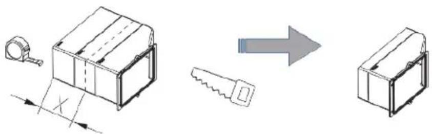
text_image
Technical diagram illustrating a mechanical assembly process with labeled components and directional arrowX=186-B
Fig./Img./Abb./Afb./Rys. 23
text_image
BACK FRONT BACK FRONTFig./Img./Abb./Afb./Rys. 24
natural_image
Technical line drawing of a mechanical housing or enclosure with an open door and a separate panel, showing internal components and an arrow indicating direction (no text or symbols present)Fig./Img./Abb./Afb./Rys. 25
text_image
4x ST3.5x14 ① ② 1CFig./Img./Abb./Afb./Rys. 26
text_image
Technical diagram showing a device interior with labeled components and three close-up insets illustrating the process.Fig./Img./Abb./Afb./Rys. 27
text_image
OK! NO!Fig./Img./Abb./Afb./Rys. 28
flowchart
graph TD
    A["Initial Component"] --> B["Step 1: Insert a component with a hand icon"]
    B --> C["Step 2: Reassembly to a device with checkmark and cross symbol"]
    C --> D["Step 3: Reassembly to a device with arrow and checkmark"]
Fig./Img./Abb./Afb./Rys. 29
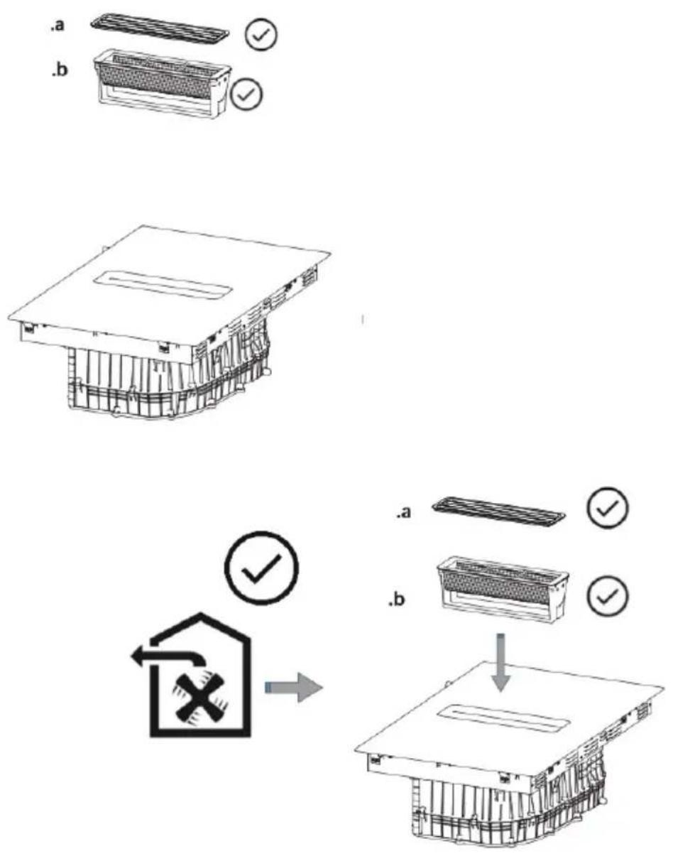
Fig./Img./Abb./Afb./Rys. 30
text_image
min 600 min 50 490 min 50 65 230 max 483 89 min 100 600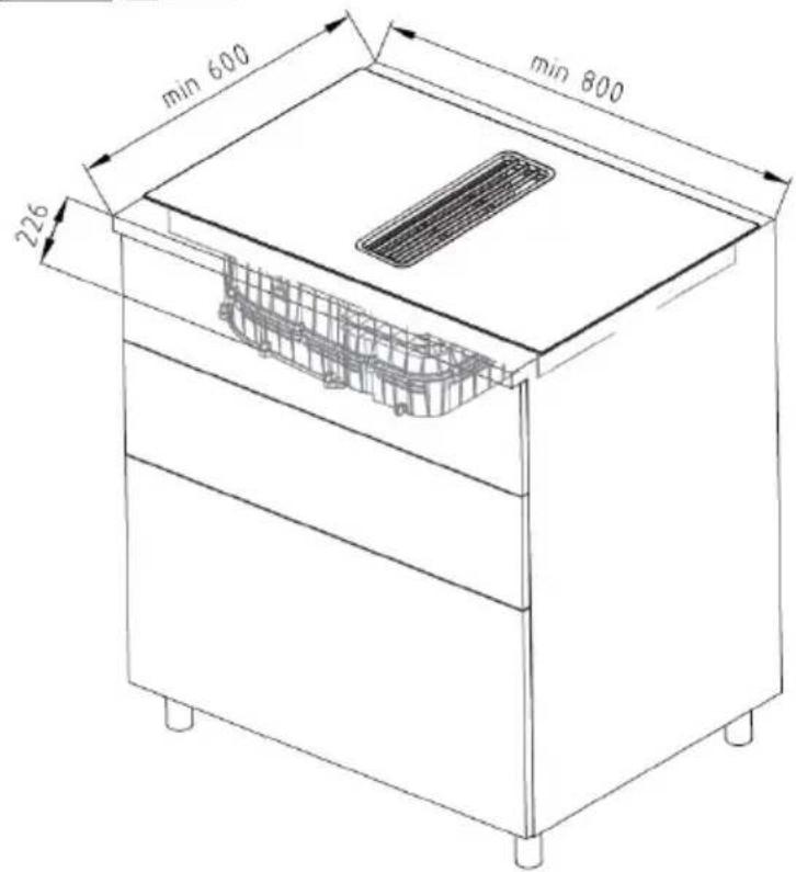
text_image
min 600 min 800 226OK!
Fig./Img./Abb./Afb./Rys. 31
text_image
Diagram illustrating a safety inspection process with labeled components and checkmarks indicating approval.Fig./Img./Abb./Afb./Rys. 32
flowchart
graph LR
    A["3D Box"] --> B["1"]
    B --> C["2"]
    C --> D["3"]
    D --> E["4"]
    style A fill:#f9f,stroke:#333
    style B fill:#ccf,stroke:#333
    style C fill:#cfc,stroke:#333
    style D fill:#fcc,stroke:#333
    style E fill:#cff,stroke:#333
Fig./Img./Abb./Afb./Rys. 33
text_image
Technical diagram showing a mechanical assembly before and after disassembly, with warning indicators and component labels in Chinese.Fig./Img./Abb./Afb./Rys. 34
text_image
Technical diagram showing a mechanical assembly with directional arrows and a magnified view of the component's rotation.Fig./Img./Abb./Afb./Rys. 35
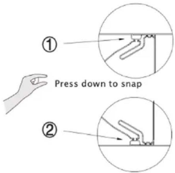
text_image
① Press down to snap ②Fig./Img./Abb./Afb./Rys. 36
text_image
We do nothing use that the phone !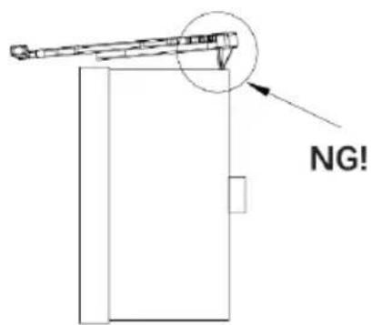
text_image
NG!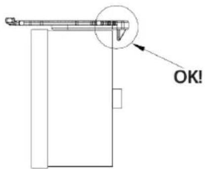
text_image
OK!Fig./Img./Abb./Afb./Rys. 37
text_image
This side faces up, open it here when cleaning.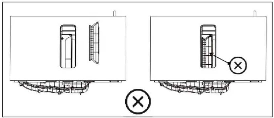
text_image
Technical diagram showing two views of a device with internal components and a marked cross symbol indicating a specific component.Fig./Img./Abb./Afb./Rys. 38
text_image
Min. 40mmFig./Img./Abb./Afb./Rys. 39
text_image
GY BU GN/YE BK BN N1 N2 L1 L2 A#V-2-023 A#V-2-022220-240V/380-415V
text_image
GY BU GN/YE BK BN N L1 L2 220-240V220-240V/380-415V
text_image
GY BU GN/YE BK BN N 220-240V L220-240V 1N-
Fig./Img./Abb./Afb./Rys. 40
text_image
Diagram showing two hand-drawn tools with check and cross symbols, likely illustrating correct and incorrect positioning.Fig./Img./Abb./Afb./Rys. 41
natural_image
Three identical cooking pots with crossed-out x-marks, no text or symbols presentFig./Img./Abb./Afb./Rys. 42
natural_image
Four identical cooking pots with crossed-out X marks, shown in a row (no text or symbols)Fig./Img./Abb./Afb./Rys. 43
natural_image
Two cooking pots with crossed arrows indicating heating or resistance, one pointing left and the other pointing up (no text or symbols)Fig./Img./Abb./Afb./Rys. 44
text_image
1 2 3 4 5Fig./Img./Abb./Afb./Rys. 45

text_image
0 15 0 15Fig./Img./Abb./Afb./Rys. 46

Fig./Img./Abb./Afb./Rys. 47

Fig./Img./Abb./Afb./Rys. 48
text_image
PO 74 00Fig./Img./Abb./Afb./Rys. 49
text_image
0 15Fig./Img./Abb./Afb./Rys. 50
text_image
Exploded view diagram of a mechanical assembly with numbered parts labeled 1 to 5Fig./Img./Abb./Afb./Rys. 51
natural_image
3D rendering of a mechanical assembly with layered components and a central cavity (no text or symbols visible)Fig./Img./Abb./Afb./Rys. 52
natural_image
3D diagram showing a block being inserted into a rectangular cavity, with arrows indicating direction (no text or symbols)Fig./Img./Abb./Afb./Rys. 53
natural_image
3D diagram of a mechanical assembly with a block and two vertical rods mounted on a flat base (no text or symbols)Fig./Img./Abb./Afb./Rys. 54
natural_image
3D rendered mechanical assembly with a bracket and mounting base (no text or symbols visible)Fig./Img./Abb./Afb./Rys. 55
www.cecotec.es