Firenze 16.7 DVR - Surveillance Camera FRACARRO - Free user manual and instructions
Find the device manual for free Firenze 16.7 DVR FRACARRO in PDF.
Frequently Asked Questions - Firenze 16.7 DVR FRACARRO
User questions about Firenze 16.7 DVR FRACARRO
0 question about this device. Answer the ones you know or ask your own.
Ask a new question about this device
Download the instructions for your Surveillance Camera in PDF format for free! Find your manual Firenze 16.7 DVR - FRACARRO and take your electronic device back in hand. On this page are published all the documents necessary for the use of your device. Firenze 16.7 DVR by FRACARRO.
USER MANUAL Firenze 16.7 DVR FRACARRO
| DVR FIRENZE | |||
| Video | Input 16 BNC with loop out | ||
| Output | VGA / S-Video / 2 BNC (monitor e spot) | ||
| Standard NTSC/PAL manual selection | |||
| Signal 1.0Vp-p, 75 W unbalanced typo BCN | |||
| Input 4 | n° | ||
| Output | 2 Audio | ||
| Signal 100mV - 2Vrms | |||
| Functions Recording, Live, Playback, Control, Backup and Network | |||
| Recording | |||
| Frame rate (adjustable for each camera) | NTSC | Fps | 480 (360×240), 240 (720×240), 120 (720×480) |
| PAL | 400 (360×288), 200 (720×288), 100 (720×576) | ||
| Quality | Adjustable for each camera with 9 levels | ||
| Modality | Manual / Scheduling / Motion / Alarm / Pre and Post alarm (0-60 sec) | ||
| Scheduling | Time and frame rate adjustable for each camera | ||
| Compression | video | std | H264 |
| audio | ADPCM | ||
| Search | Date / time / motion / video loss / Camera / Smart Search | ||
| Hard disk | Type | SATA, internal mount and eSATA external | |
| Capacity max | GB | 4 disks with 2TB each one (8TB max) | |
| Overwrite | Full disk stop / Full disk overwrite / Time adjustable overwrite (Privacy) | ||
| Partition | Double partition size adjustable for alarm and normal recording | ||
| Security | Failure event detection | ||
| Estimated Recording time CIF (352x288) with medium quality (5) | 160 GB | days | 2 (200 fps) |
| 750 GB | 9.4 (200 fps) | ||
| 2 TB | 25.2 (200 fps) | ||
| Display | |||
| Resolution | NTSC | pixels | 720×480 |
| PAL | 720×576 | ||
| Speed | Real time | ||
| Mode | Full screen / Quad / 7/9/10/13/16 Sequential | ||
| Zoom | X2 and x4 on live | ||
| Motion detection | Detection areas and sensitivity adjustable for each camera | ||
| Network | |||
| Connection | RJ45, Ethernet 10/100 baseT Mbit | ||
| Communications | Protocols | TCP/IP, HTTP, PPPoE, DHCP, DDNS, FTP, TSP | |
| Ports | Independent configuration for data and Control | ||
| Functionalities | Remote control, Live view with PTZ facility, Backup, fw upgrade | ||
| Event management | Mail notification and ftp recording | ||
| Users | Max 8 users simultaneously | ||
| User interface | |||
| Protection | Multilevel Password (3) and multi-user (18) | ||
| Local | Frontal keyboard, USB mouse, remote control (up to 4 dvr), optional control keyboard with 3-axis joystick (up to 256 DVR) | ||
| Remote | PC | Browser | Full management (up to 4 DVR) by ActiveX control |
| CMS | Full management (up to 4 DVR) with interactive graphic maps | ||
| Mobile | Live (Quad/Full screen) with adjustable resolution, input alarms | ||
| phone/ Smartphone/ PDA | status monitoring, output relay activation (home automation facility) | ||
| Event management | |||
| Detected events Type Motion detection, video loss, input alarms | |||
| Alarms (TTL/CMOS selectable polarity) | Input 16 | n.° | |
| Output | 2 NO, 2 NC | ||
| Buzzer Programmable for each event | |||
| Connections | |||
| Serial communication | RS485 (D+, D-), RS-232 | ||
| PTZ control | Pelco D, Pelco P, Samsung SCC-641P, Kalatel Cyber Dome, Bosch AutoDome and other protocols... | ||
| Backup | USB 2.0 (Pendrive, external hard disk self-powered, External DVD burner self-powered, SD-MMC Card) / eSATA for external hard disk / Internet Explorer / CMS / Internal DVD burner (optional) | ||
| Generals | |||
| Power supply ~ | ON/OFF switch | V, Hz | 220 Vac 50Hz |
| Power | W | 110 W | |
| Operating Temperature | °C | 0 - 45 | |
| Operating Humidity | Ur % | <80 | |
| Dimensions (w×l×h) | mm | 430 x 330 x 88 | |
| Weight | kg | 5 (without hard disk) | |
1 Pannello frontale - Frontal Panel - Panneau frontal Panel delantero - Painel dianteiro - Πρόσουψη - Panel Czołowy - Voorpaneel
2 Pannello posteriore - Back Panel - Panneau arriffe Panel trasero - Painel traseiro - Πίσω ὄψη - Panel Tylny - Achterpaneel
3 Connessioni - Connections - Connexions Conexiones - Conexoes - - Connecties
Fig.1
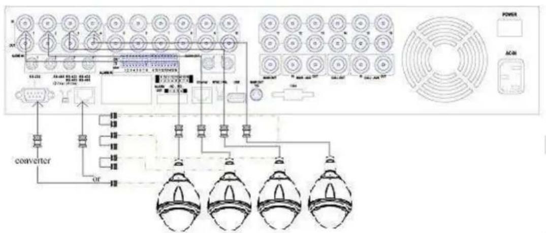
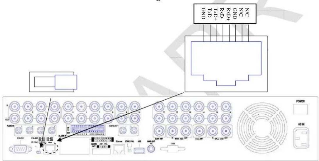
Fig.2
Fig.3
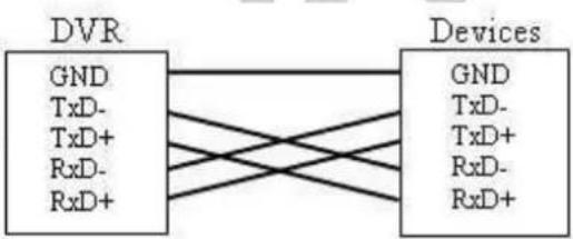
For 4-line devices (such as keyboard)
For PTZ cameras
Fig.4
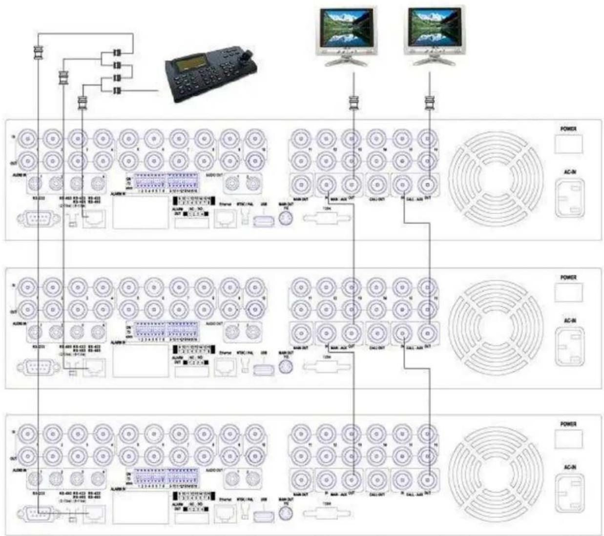
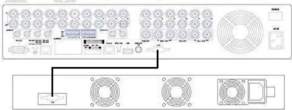
Fig.5
Fig.6
4 Telekomando - Remote control - Telekomande
Mando a distancia - Controlo remoto - Tηλεχειριστήριο - Pilot Zdalnego Sterowania - Afstandsbediening
Note: This currently doesn't have any active Dynamic R2010 updates in your database. It cannot cause some of our most Service features. Firing it in an Old R2010 R2010 Upgrade will make this form fully functional and we hold several other features.
Instructions Picture
| RS-232/ 422 /485 Setup | ||
| COM Port | RS-232 | RS-422/485 |
| Device Type | PTZ | |
| Model | Pelco (D-Type) | |
| Baud Rate | 4800 | |
| Data Bit | 8 | |
| Stop Bit | 1 | |
| Parity | None | |
| DVR/Camera ID | 0 | |
| Pre-Camera Setup | ||
| REC Resolution 720x288 | ||
| Watermar√ Group | ||
| Camera Installed PTZ ID | 1 2 3 4 5 6 7 | |
| 1 | √ N/A | |
| 2 | √ 1 | |
| ... | ... | ... |
ATTENTION: This user manual is a quick guide for the first installation of the DVR please refer to the user manual to know the complete information of all the single functions.
Table of contents:
1- Safety warnings . . . . . . . . . . . . . . . . . . . . . . . . . . . . . . . . . . . . . . . . . . . . . . . . .
1.1-ContentPackage .pag.23
2- Product Overview . . . . . . . . . . . . . . . . . . . . . . . . . . . . . .
3- Panels and remote controller . . . . . . . . . . . . . . . . . . . . . . . . . . . . . . . . . . . . . . . . . . . . . . . . . . . . . .
3.1-Front Panel . pag.24
3.2-Back Panel . . . . . . . . . . . . . . . . . . . . . . . . . . . . . . . . . . . . . .
3.3 - Remote controller . . . . . . . . . . . . . . . . . . . . . . . . . . . . . . . . . . . . . . . . . . . . . . . . .
3.4 - Mouse . .25
4- Installation . . . . . . . . . . . . . . . . . . . . . . . . . . . . . . . . . . . . . . . . . . . . . . .
4.1-Power on and off . 25
4.2-HDD setup . pag.25
4.3-First access to the DVR . .pag.26
5- Basic use of the DVR. pag.29
5.1-Search .pag29
5.2-Backup . .30
5.3-Viewing the images . pag.30
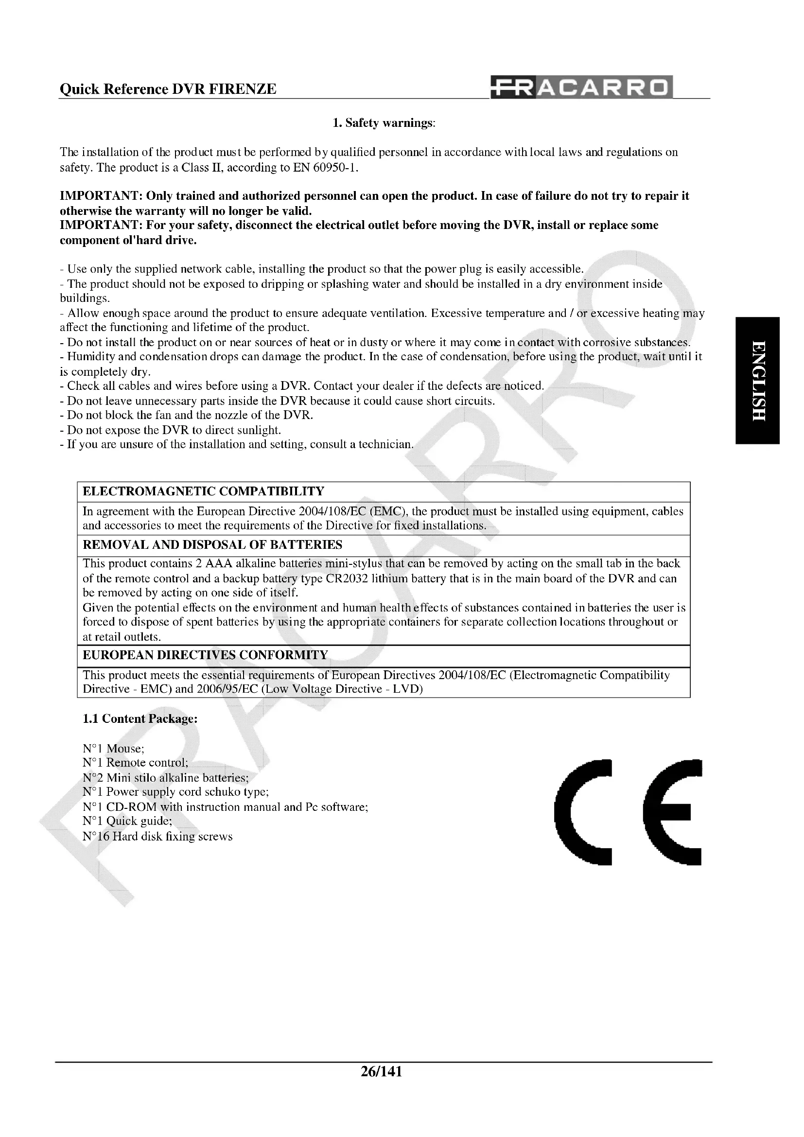
The installation of the product must be performed by qualified personnel in accordance with local laws and regulations on safety. The product is a Class II, according to EN 60950-1.
IMPORTANT: Only trained and authorized personnel can open the product. In case of failure do not try to repair it otherwise the warranty will no longer be valid.
IMPORTANT: For your safety, disconnect the electrical outlet before moving the DVR, install or replace some component of 'hard drive.
- Use only the supplied network cable, installing the product so that the power plug is easily accessible.
- The product should not be exposed to dripping or splashing water and should be installed in a dry environment inside buildings.
- Allow enough space around the product to ensure adequate ventilation. Excessive temperature and / or excessive heating may affect the functioning and lifetime of the product.
- Do not install the product on or near sources of heat or in dusty or where it may come in contact with corrosive substances.
- Humidity and condensation drops can damage the product. In the case of condensation, before using the product, wait until it is completely dry.
- Check all cables and wires before using a DVR. Contact your dealer if the defects are noticed.
- Do not leave unnecessary parts inside the DVR because it could cause short circuits.
- Do not block the fan and the nozzle of the DVR.
- Do not expose the DVR to direct sunlight.
- If you are unsure of the installation and setting, consult a technician.
| ELECTROMAGNETIC COMPATIBILITY |
| In agreement with the European Directive 2004/108/EC (EMC), the product must be installed using equipment, cables and accessories to meet the requirements of the Directive for fixed installations. |
| REMOVAL AND DISPOSAL OF BATTERIES |
| This product contains 2 AAA alkaline batteries mini-stylus that can be removed by acting on the small tab in the back of the remote control and a backup battery type CR2032 lithium battery that is in the main board of the DVR and can be removed by acting on one side of itself.Given the potential effects on the environment and human health effects of substances contained in batteries the user is forced to dispose of spent batteries by using the appropriate containers for separate collection locations throughout or at retail outlets. |
| EUROPEAN DIRECTIVES CONFORMITY |
| This product meets the essential requirements of European Directives 2004/108/EC (Electromagnetic Compatibility Directive - EMC) and 2006/95/EC (Low Voltage Directive - LVD) |
1.1 Content Package:
N^1 Mouse;
N^1 Remote control;
N^2 Mini stilo alkaline batteries;
N^1 Power supply cord schuko type;
N^1 CD-ROM with instruction manual and Pc software;
N^ 1 Quick guide;
N^16 Hard disk fixing screws
C E
2. Product Overview:
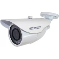
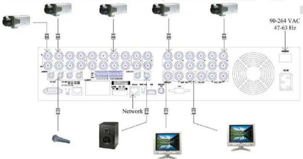
The DVR FIRENZE is digital video/audio recorders designed to realize a powerful and secure surveillance system that can be interfaced with different kind of monitors, pc and smartphones. The new type of compression and the configurable quality guarantee a long time recording on the Hard Disk and a good quality of the images during the playback.
The new processor allows the DVR to do six different operation like: simultaneous record, realtime live display, playback, backup, control & remote access.
The high number of frame for recording allow REALTIME recording.
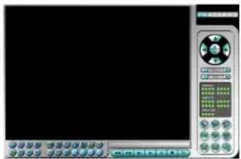
It can be managed by the front panel, mouse, remote control, external keyboard, virtual keyboard and web interface with a Pc or a smartphone.
The two output relay can be activated by input alarm, motion, video loss, system event or directly with the mobile phone or the web interface.
3. Panels and Remote Controller:
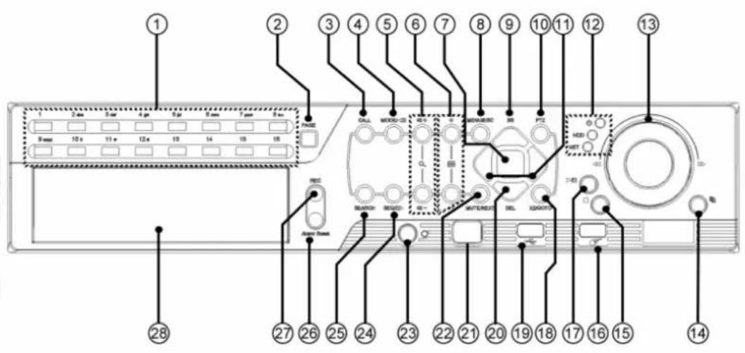
3.1 Front Panel (refer to figure 1):
| N° | Button Function | N° | Button Function | ||
| 1 | Alpha-numeric Buttons | Used for enter text 15 STOP Stop the display | playback | ||
| 2 | PAGE Display in | multi-split-windows 16 USB Mouse | USB mouse connector | ||
| 3 | CALL Switch to | or return from full screen display | 17 PLAY/ PAUSE | Play or pause the playback | |
| 4 | MODE | Toggle between live and playback mode | 18 X2/ GOTO | PTZ management | |
| 5 | Vol/ Zoom +/- | Adjust volume and zoom | 19 | USB | USB connector |
| 6 | SPLIT Windows +/- | Previouss/ next split window | 20 | DOWN / DEL | Move the cursor or Tilt down the camera or Delete |
| 7 | ENTER | Enter Key | 21 Remote IR sensor | IR detector | |
| 8 | MENU / ESC | Display or ESC the menu | 22 MUTE/ NEXT | Mute audio, ptz management | |
| 9 | UP / BS | Move the cursor or Tilt up the camera or Backspace | 23 DVR IR Switch | Set ID DVR for remote control | |
| 10 | PTZ | PTZ management | 24 | SEQ | Start SEQ mode |
| 11 | LEFT / RIGHT | Move the cursor or Pan the camera | 25 SEARCH | Start search mode | |
| 12 | LEDs | Indicators for Power, Hdd, net | 26 | Alarm reset | Alarm reset button |
| 13 | Jog/ Shuttle | Playback management | 27 | REC | Rec button |
| 14 | COPY | Start or stop backup | 28 | DVD optional | DVD burner optional |
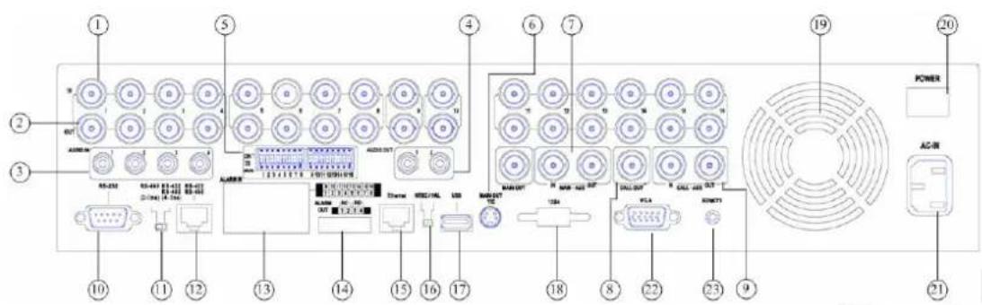
3.2 Back Panel (refer to figure 2):
| N° | Connector | N° | Connector |
| 1 | Video BNC input connector | 13 | Alarm Input Connectors |
| 2 | Video BNC output connector | 14 | Alarm Output Connectors |
| 3 | 4 Audio input RCA connector | 15 | Ethernet Connector |
| 4 | 2 Audio output RCA connector | 16 | NTSC/PAL Selector Switch |
| 5 | 75Ω termination | 17 | USB Connector |
| 6 | Main Monitor Output Connectors | 18 | eSata Connector |
| 7 | MAIN-AUX Connectors | 19 | Cooling Fan |
| 8 | Call Monitor Output Connector | 20 | Power Switch |
| 9 | CALL-AUX Connectors | 21 | Power Cord Inlet |
| 10 | RS-232 Connector | 22 | VGA Connector |
| 11 | RS-422/485 Selector Switch | 23 | Remote sensor connector |
| 12 | RS-422/485 Connector |
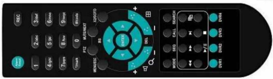
3.3 Remote Controller (refer to figure 3):
The remote controller is an optional accessory to ease the user's operations. You can do all the operations by the remote controller instead of the buttons on the front panel. The effective distance is about 10 meters without any obstacle.
| N° | Key Function | N° | Key Function | ||||
| 1 | Alarm Reset | ENTER | Right | ||||
| 2 | REC | Start/Stop Recording 15 | Enter | ||||
| 3 | Rewind 16 | MUTE/NEXT | Enable or disable audio/Next | ||||
| 4 | Forward 17 | X2/GOTO | Level of zoom/Goto preset | ||||
| 5 | Play step by step 18 | + Q- | Adjust the volume or the zoom level | ||||
| 6 | Start backup or copy informations | 19 | Change the division of the screen | ||||
| 7 | Play/pause 20 | 1 2woc 3woc 4woc 5woc 6woc 7woc 8woc 9woc 10woc 0 mode | Insert text, numbers or code | ||||
| 8 | Stop 21 | MODE | Toggle between Live andPlayback mode | ||||
| 9 | MENU/ESC | Enter menu 22 | SEQ | Switch or return to sequence mode | |||
| 10 | PTZ | Esc or start PTZ mode 23 | CALL | Switch or return to full screen mode | |||
| 11 | BS | Up/Backspace | 24 | SEARCH | Display the search menu | ||
| 12 | DEL | Down/Delete | 25 | DVR1 | Select the DVR to be controlled by remote controller | ||
| 13 | Left | ||||||
3.4 Mouse:
The DVR can be easily managed by the mouse. Please connect the mouse before connecting the power supply and then move the cursor on the bottom of the screen to view the setup menu.
4. Installation:
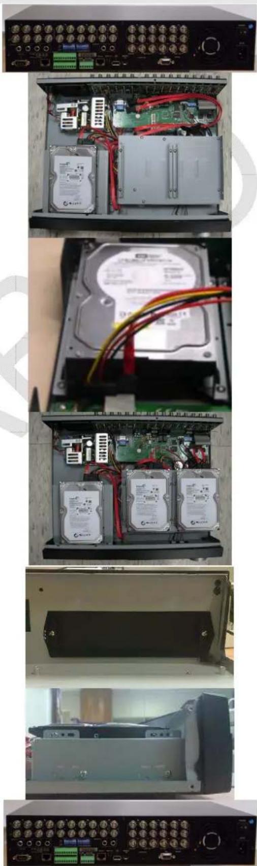
4.1 HDD Setup:
Please follows the steps below for a correct installation of the HDD and the DVD Writer on the DVR.
N Instructions Picture
1 Take the DVR and disconnect all the cables.
2 Remove all the screws (7) on the rear (3) and lateral panel (2 + 2) .
3 Remove the cover as shown.
4 From the bag of DVR accessories take the 2 brackets and fix them on the HDD using the 4 screws.
5 From the bag of DVR accessories take the 4 screws and fix the HDD on the DVR and connect the data and power cables.
6 Return to the step number 4 to install the other 3 optional HDD.
7 It is possible to install, as optional, a DVD writer that will be placed in the housing of the third HDD. To install this device remove the 2 screws and the plastic cap.
8 From the bag of DVR accessories take the 2 brackets, fix them on the DVD writer and install the device on the DVR connecting the cables.
9 Using all the screws close the cover, connect the monitor and the power supply. Now the DVR is installed and ready to use. Please refer to the manual to setup the time and format all the HDDs.
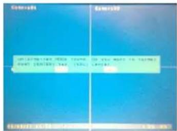
10 Turn On the DVR using the apposite buttom on the rear panel of the DVR. The DVR will show the message: "Unformatted HDDs found. Do you want to format now? [ENTER]: Yes, [ESC]: Cancel". Press the [ENTER] button to format the hard disk.
4.3 First access to the DVR:
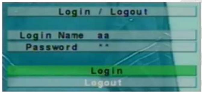
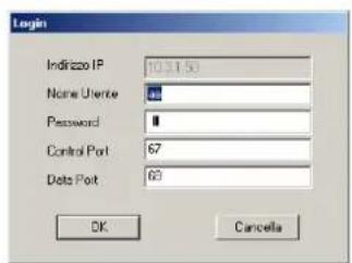
- Login
After turning on the DVR, press the "MENU" button and then move the cursor on the icon called "Login/Logout" and press "ENTER".
Now enter the name and password. Parameters from the factory's installer has a user name: "aa" and password "11". Move the cursor on "Login" and confirm by pressing "ENTER".
There are three password levels in the system, including: Administrator (highest), Supervisor, and Operator (lowest). The Operator can operate live video display, the Supervisor live video display, image playback and archive, and the Administrator everything.
CAUTION: The factory setting of the DVR takes only one user configured as an administrator. In order to increase the level of security you should use that user for only the first access and change the password as soon as possible.
WARNING: In case of loss of the system password please contact your local distributor who will contact Fracarro Radioindustrie S.p.A.
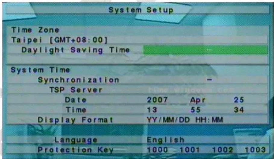
- Setting Language
Faithfully follow the steps below to configure the language of the DVR:
- Press the "MENU" button to access the configuration menu;
- Move the cursor to "SETUP" and confirm by pressing "ENTER";
- Move the cursor to the "SYSTEM" and confirm by pressing "ENTER";
- Using the arrow keys move the cursor to the "LANGUAGE" and press the keys +/- to set the desired language;
- Press the "MENU" button to return to the previous menu, the DVR will be prompted to save the settings by pressing the "ENTER";
- Press "ENTER" to confirm the change of language. The system will restart with the new settings.

- Adjust Date / Time:
Faithfully follow the steps below to adjust the date / time:
- Press the "MENU" button to access the configuration menu;
- Move the cursor to "SETUP" and confirm by pressing "ENTER";
- Move the cursor to the "SYSTEM" and confirm by pressing "ENTER";
- Using the arrow keys move the cursor to the "DATE" and, using the keys "+" set the year, month and day;
- Using the arrow keys move the cursor on "TIME" and, using the keys "+" set the time;
- Press the "MENU" button to return to the previous menu, the DVR will be prompted to save the settings by pressing the "ENTER";
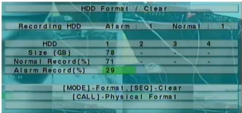
- Formatting the hard disk:
Faithfully follow the steps below to format the hard disk:
- Press the "MENU" button to access the configuration menu;
- Move the cursor to "SETUP" and confirm by pressing "ENTER"; Move the cursor to the heading "HDD" and confirm by pressing "ENTER";
- Press the "MODE" button;
- Press the "CALL" button to format the entire hard drive;
- Press "ENTER" to confirm the operation;
- Press the "MENU" button to return to the previous menu.
- Setting the record:
The DVR allows different recording modes: alarm, motion, continuous or scheduled. Using the last mode, the system administrator can define, for each hour of the week, the type of registration.
In order to customize the recording schedule every day is divided into a maximum of 16 segments (T1, ..., T16) which can be configured in 3 different recording modes to choose from: recording video, audio+video recording or absence of registration.
NOTE: The DVR is factory programmed to record continuously during the whole week.
Faithfully follow the steps below to set the schedule:
- Press the "MENU" button to access the configuration menu;
- Move the cursor to "SETUP" and confirm by pressing "ENTER";
- Move the cursor to the heading "SCHEDULE RECORDING" and confirm by pressing "ENTER";
- Press "MODE" button;
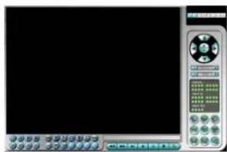
- The following screen will appear:
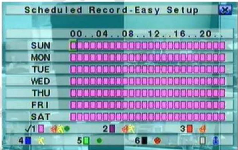
This screen allows the administrator an easy and fast way to program the schedule recording. It is possible, for each hour of the week, to set the way of recording from: Alarm+Motion+Normal, Alarm+Motion, Alarm, Motion, Normal, and no Recording. It will be recorded both audio and video.
Button description:

Press these button to move the cursor.
Numeric 1-6 (Mouse: Left click)
Press these buttons to select the recording mode. Press ENTER button to activate the mode. Recording modea are: "1" - Alarm+Motion+Normal, "2" - Alarm+Motion, "3" - Alarm, "4" - Motion, "5" - Normal, "6" - No Recording.
+/- (Mouse: Left click)
Press these buttons to select the desidered time interval. Press ENTER button to activate the recording mode on the selected time interval.
ESC (Mouse: Right click)
Press these buttons to esc the screen and return to the previous. Time segment will be updated..
5 Basic use of the DVR:
5.1 Search:
The DVR allow 4 different ways to search the image like: search by time, search by event, smart search or search on archived files.
The screen for "SEARCH BY TIME", on the bottom, shows the date when the recording started so it is possible to know how long is the recording and select a specific date for search the image. It is possible to reduce the searching time by selecting the type of recording like Alarm, Motion, Video loss or Normal.
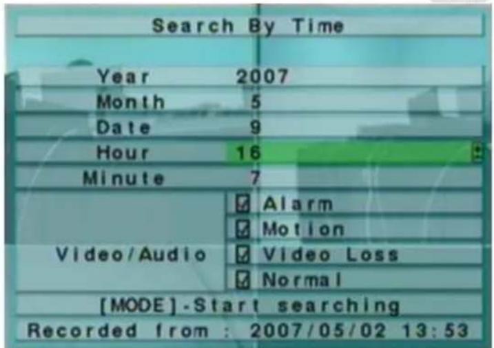
Faithfully follow the steps below to make an image search:
- Press the "SEARCH" to enter the Search menu;
- Move the cursor on "SEARCH BY TIME" and confirm by pressing "ENTER";
- Move the cursor over the heading "YEAR", "MONTH", "DATE", "HOUR" and "MINUTE" to select the start date of research using the keys +/-;
- Move the cursor over the headings "ALARM", "MOTION", "VIDEO LOSS" and "NORMAL" to select the type of recording you want to search using the buttons +/-;
- Press "PLAY" to start the playback;
- Press the " " and "▶" to increase or decrease the speed of display and the button "▶ / ]] " to pause or play the video;
- Press the "STOP" to exit the playback mode.
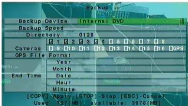
5.2 Backup:
The DVR permits to backup the video/audio recording on different type of external USB devices like pendrive, self-powered HDD or DVD Writable. Please refer to the previous section to know how to install and connect all the devices:
- Press the "SEARCH" button;
- Move the cursor on "SEARCH BY TIME" and confirm by pressing "ENTER";
- Move the cursor over the heading "YEAR", "MONTH", "DATE", "HOUR" and "MINUTE" to select the start date of research using the keys +/-;
- Move the cursor over the headings "ALARM", "MOTION", "VIDEO LOSS" and "NORMAL" to select the type of recording you want to search using the buttons +/-;
-
Press the "COPY" button;
-
Move the cursor on "BACKUP SPEED" and select the value of the backup rate from 1 (slow) to 9 (fast) using the keys "+"
- Move the cursor on "CAMERAS" to select the camera that you want to backup using the keys "+"
- Move the cursor over the heading "YEAR", "MONTH", "DATE", "HOUR" and "MINUTE" to select the time and date of end of backup using the keys +/-;
- Press the "COPY" to start the backup.
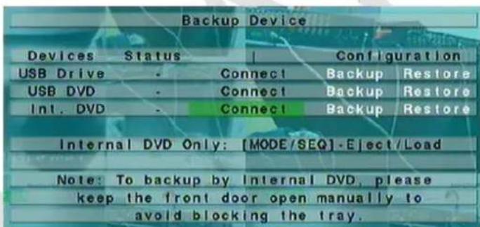
Throughout the backup process will receive an icon and a message indicating the progress of the procedure. Once the procedure is necessary to disconnect the device acting on the appropriate menu:
- Press the "MENU" button to access the system menu;
- Move the cursor on "BACKUP DEVICE" and confirm by pressing "ENTER";
- Move the cursor over the headings "USB DRIVE", "USB DVD" or "SD CARD" to select the type of connected device and press "ENTER" to disconnect;
- At this point you can physically disconnect the backup device from the DVR.
CAUTION: Do not remove the DVD until the backup process is not completely finished to prevent damage to the optical drive.
CAUTION: Do not remove the USB device until the backup process is not completely finished.
5.3 Viewing the images:
During the backup the DVR creates two folders on the device, one containing the backup files and the other containing the display of images (SelfPlayer). Follow the steps below to view images:
- Connect the backup device used on a PC;
- Start the software "Selfplayer" contained in the folder "SELFPlayer";
- Press the "FILE" then "OPEN";
- Select the file you want to display (in the folder "00001") and confirm with the button "OPEN".
The DVR backup splits the video into multiple files of maximum size of 100Mb which can subsequently be joined to form a single file "avi" using the software "AVIConverter" provided.
6 Shut down:
Before turning off the DVR, press the "MENU" button and then "SHUTDOWN" and confirm by pressing "ENTER". Press "ENTER" again to request for confirmation of the command. Only when the DVR displays the message "Shutdown complete. Now you can turn off the system, you can turn off the DVR using the appropriate key on the back panel of the DVR.
7.1 Recording table:
7 Appendix:
In order to choose the correct size of hard disk to install on the DVR is a table showing the maximum recording time at CIF resolution (360x288) and maximum quality (9) for each type of DVR and hard drive size:
250 1.6
500 3.1
1000 6,3
2000 12.6
ATTENTION: The DVR divide the HDD in two different partitions, the largest one (70% of the maximum capacity of the HDD) is used for the normal recording and the other one (30%) for pre-alarm and pre-motion recording.
Please wait the complete start of the DVR before entering the menu, then press "MENU" in split-window display to call up Menu display, than press login/loginout to access to the function of the DVR.
Please before shutting down the system press "MENU" in split-window display to call up Menu display and press
"Shutdown" then, when the DVR shows "Shutdown completed. You may turn off the system now", it will be possible to power off the DVR with the apposite switch on the rear panel.
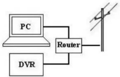
7.2 PC Network connection:
The DVR can be connect to a Ethernet or Internet network. In both case it is possible to manage more DVRs from the same PC and the same CMS (Central Monitoring System) or view the image and manage the output relay directly from a mobile phone or a Web browser also different from Internet Explorer.
The first type of connection is made by a cross Ethernet cable that connect the DVR (Fig.A) and the PC or by switch, hub or a router (Fig.B):

Fig.A

Fig.B
In both case please refer to the following steps to configure the connection:
Instructions Picture
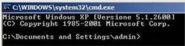
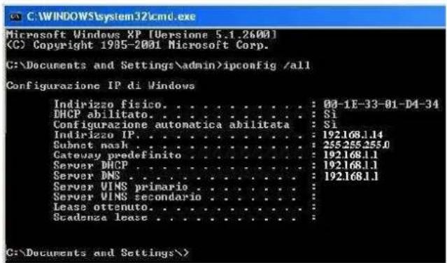
First of all go to a pc, connected to the same network of the DVR, access to start/run then enter "cmd" and press Enter. The DOS prompt will appear.
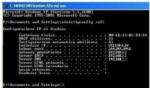
On the screen enter "ipconfig /all" and press Enter. The screen will show all the PC Network information so it is possible to know which are the Gateway (Ex. 192.168.1.1) and the PC IP Address (Ex. 192.168.1.14).
Please return to the DVR, press MENU than SETUP and NETWORK SETUP to access to the "Network Setup" menu. In this screen enter an IP address (Ex. 192.168.1.15) that isn't used by other network devices and the same Gateway
HDD (GB) DVR FIRENZE (days)
| Net type | Static IP E-mail | FTP Adv. |
| IP Address | 192.168.1.15 | |
| Static IP | Net Mask | 255.255.255.0 |
| Gateway | 192.168.1.1 | |
| DNS |
(Ex.192.168.1.1) and Net mask (Ex. 255.255.255.0) of the PC.
ATTENTION: The IP Address that will be assigned to the DVR must be different from the PC one only in the last number.
Please enter the IP address of the DVR (Ex. 192.168.1.15) in the search bar of Internet Explorer and press Enter.
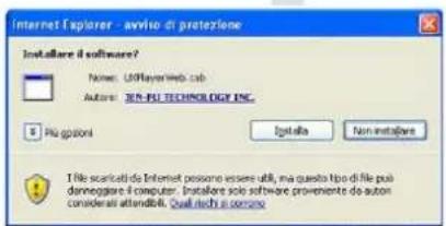
The Browser will ask to install the ActiveX control, please confirm all the request. The connection could be interrupt by the firewall or the antivirus so please be sure that they aren't active.
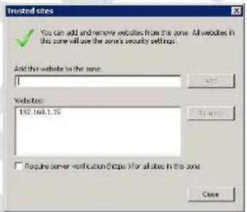
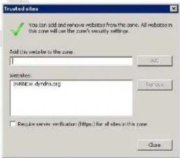
If the browser won't show the image please insert the IP address of the DVR in the "Trusted sites" menu.
Please insert the User ID and password of the user that will access to the DVR.
ATTENTION: The default user is the administrator and he has user ID: aa and password:11
Now, using Internet Explorer is it possible to view the image and manage until 4 different DVRs.
Using Firefox or other Web browser it is possible to view the image, the state of the input alarm and manage the output alarm of the DVR.


ATTENTION: If the connection is made by a cross cable please don't insert the Gateway IP address.
Now the DVR is correctly connect to the Ethernet network, if the connection is made using a router it is possible to connect the DVR through Internet and view the same information all over the world (Fig. C).
Please follow the steps below to configure the connection:
Instructions Picture
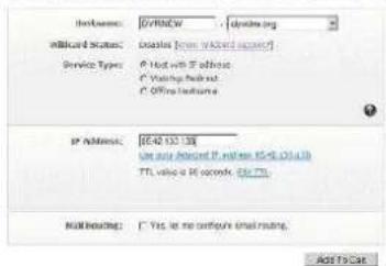
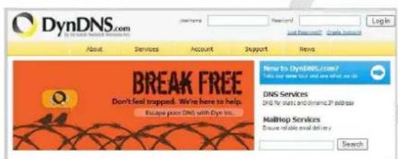
Please access to the website www.dyndns.org and press "Create Account".
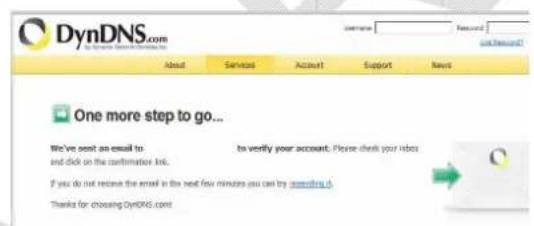
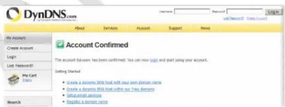
An E-mail with all the informations will be sent to the E-mail address inserted. Please follow the instructions to activate the new account.
Insert the username and password of the new dyndns account.
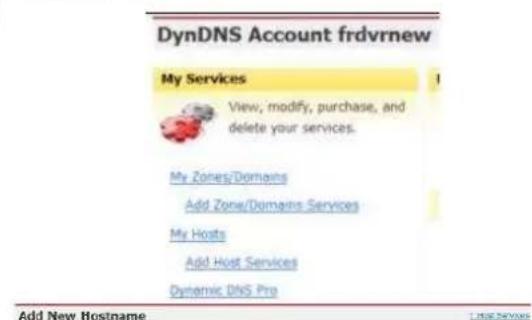
Click on "Add Host Services"
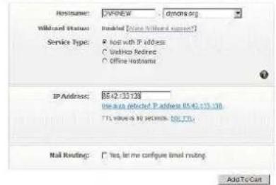
Select a new Hostname of the DVR, click on "Use auto detect IP Address" and confirm all the requests to activate the new Host.
Using Internet Explorer enter the IP Address of the router (Gateway) and press Enter, a screen will ask to enter the user ID and password of the router, please find this information on the instruction manual of the device.
Note: Your currently does not have any active Dynamic file extensions in your account. You cannot use one of our Host Service features. Paying for an dynamic DNS file upgrade will make this form fully functional and will add several other features.

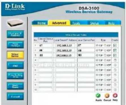
Please follow the installation manual of the Router to create a rule for the 67, 68 and 80 port for the DVR IP Address and TCP protocol.
NOTE: Please refer to the www.portforwarding.com website to know the correct way to configure the router
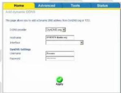
Please follow the installation manual of the Router to insert the DDNS information like username, password and hostname of the DVR.
Now the DVR is correctly connected to the network. Please make sure that the IP Address of the DVR is inserted on the "Trusted sites" of Internet Explorer
Enter the Hostname of the DVR on the search bar of Internet Explorer and it will be possible to view all the cameras.
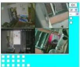
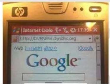
7.3 Mobile phone network connection:
The image of the DVR can be viewed using a mobile phone, smartphone or PDA connected to the internet network. Follow the steps below to create the connection:
Instructions Picture
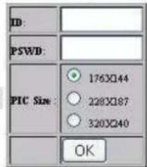
Enter the Hostname of the DVR on the search bar of the browser of the mobile phone or PDA.
The DVR will ask the user to enter his User ID and Password.
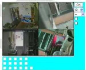
Please select the best image resolution for the mobile phone or PDA than press "OK".
Now it will be possible to view the image on the mobile phone or PDA, manage the output relays and know the state of the input alarm directly by the interface.
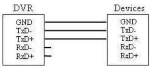
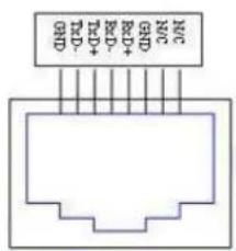
7.4 PTZ Camera connection:
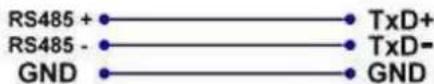
The DVR can be used for manage until 4-9-16 PTZ cameras using the RS-485 cable. (Fig D:)
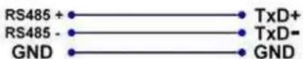
For Keyboard
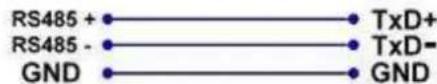
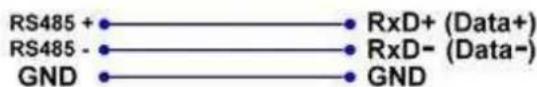
For PTZ Device
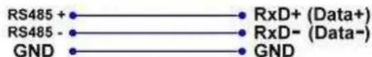
Please follow the steps below to connect a PTZ camera to the DVR:
Instructions Picture
Please follow the instruction manual of the Camera to configure it with Pelco-D (or Pelco-P) Protocol, Baud Rate of 4800 bps and a ID Address (from 1 to 255) that will be different for each camera.
Connect the BUS RS-485 of the camera to the back panel of the DVR.
Press "MENU", than "SETUP" and "RS-232/422/485 Setup" on the DVR for enter to the BUS configuration and enter the same Protocol (Model) and Baud Rate of the PTZ camera.
Press "MENU", than "SETUP" and "Pre-Camera Setup" on the DVR and enter the ID Address of the single PTZ camera.
ATTENTION: Please be sure that all cameras have different ID Address.
| RS-232/ 422 /485 Setup | ||
| COM Port | RS-232 | RS-422/485 |
| Device Type | PTZ | |
| Model | Pelco (D-Type) | |
| Baud Rate | 4800 | |
| Data Bit | 8 | |
| Stop Bit | 1 | |
| Parity | None | |
| DVR/Camera ID | 0 | |
| Pre-Camera Setup | ||
| REC Resolution | 720x288 | |
| Watermark | √ | Group |
| Camera | Installed | PTZ ID 12345678 |
| 1 | √ | N/A |
| 2 | √ | 1 |
Now the camera it is correctly connected to the DVR and is possible to manage it using the remote controller, mouse or the PC software.
| RS-232/ 422 /485 Setup | ||
| COM Port RS-232 | RS-422/485 | |
| Device Type | PTZ | |
| Model | Pelco (D-Type) | |
| Baud Rate | 4800 | |
| Data Bit | 8 | |
| Stop Bit | 1 | |
| Parity | None | |
| DVR/Camera | 0 | |
| Pre-Camera Setup | ||
| REC Resolution | 720x288 | |
| Watermark | √ | Groun |
| Camera | Installed | PTZ ID 12345678 |
| 1 | √ | N/A |
| 2 | √ | 1 |
C:\Documents and Settings\admin>
For Keyboard
For PTZ Device
5.1-Busca . pag.78
5.2-Playback .78
5.3-Visualizing as imagens .79
6-Encerre . pag.80
5,3 Visualizing as imagens:
For Keyboard
For PTZ Device

| Pre-Camera Setup | |||
| REC Resolution | 720x288 | ||
| Watermark | √ | Group | |
| Camera | Installed | PTZ ID | 1 2 3 4 5 6 7 8 |
| 1 | √ | N/A | |
| 2 | √ | 1 | |
| ... | ... | ... | |
5-Kopua xipion tou DVR. 6eA.92
5.1-Avocntn.. 0eA.92
5.2-Backup.. 92
5.3-Piopofoaiov eKovov 93
6-Papaprtnua. 0eλ.93
7-Παρτημα. 0ελ.93
| N | Button Function | N | Button Function | ||
| 1 | Alpha-numeric Buttons | Used for enter text | 15 | STOP | Stop the playback |
| 2 | PAGE | Display in multi-split-windows | 16 | USB Mouse | USB mouse connector |
| 3 | CALL | Switch to or return from full screen display | 17 | PLAY/ PAUSE | Play or pause the playback |
| 4 | MODE | Toggle between live and playback mode | 18 | X2/ GOTO | PTZ management |
| 5 | Vol/ Zoom +/- | Adjust volume and zoom | 19 | USB | USB connector |
| 6 | SPLIT Windows +/- | Previouss/ next split window | 20 | DOWN / DEL | Move the cursor or Tilt down the camera or Delete |
| 7 | ENTER | Enter Key | 21 | Remote IR sensor | IR detector |
| 8 | MENU / ESC | Display or ESC the menu | 22 | MUTE/ NEXT | Mute audio, ptz management |
| 9 | UP / BS | Move the cursor or Tilt up the camera or Backspace | 23 | DVR IR Switch | Set ID DVR for remote control |
| 10 | PTZ | PTZ management | 24 | SEQ | Start SEQ mode |
| 11 | LEFT / RIGHT | Move the cursor or Pan the camera | 25 | SEARCH | Start search mode |
| 12 | LEDs | Indicators for Power, Hdd, net | 26 | Alarm reset | Alarm reset button |
| 13 | Jog/ Shuttle | Playback management | 27 | REC | Rec button |
| 14 | COPY | Start or stop backup | 28 | DVD optional | DVD burner optional |
Esc of start PTZ mode 23
11

Naar beneden/Delete 25
13

Links
3.4 Muis:

Funzione
Rechts
Enter
Audio activeren of deactiveren/ Volgende
Zoom-niveau / Gaaar preset
"Unformatted HDDs found. Do you want to format now? [ENTER]: Yes, [ESC]: Cancel".