AS1150 - To scan AGFA - Free user manual and instructions
Find the device manual for free AS1150 AGFA in PDF.
| Product Type | Photo Scanner |
| Brand | AGFA |
| Model | AS1150 |
| Sensor Type | Color Contact Image Sensor (CIS) |
| Dimensions (L × H × D) | 158 × 45 × 55 mm |
| Weight | 0.23 kg |
| Power Supply | Input: 100-240 V~ 50-60 Hz, Output: 5 V / 1 A |
| Power Consumption | Less than 9 W |
| Photo Resolution (optical) | 300 × 300 dpi |
| Film/Slide Resolution (optical) | 1200 × 1200 dpi |
| Color Depth Input | 48 bits |
| Color Depth Output | 24 bits |
| Compatible Paper Formats | Min. 42 × 20 mm, Max. 105 × 304.8 mm, 50-105 g/m² |
| Compatible Film Formats | 35mm color negative strips (6 frames), 35mm unframed slide |
| Film Type Recognition | Automatic (color, B/W, slide) |
| Computer Connection | USB 2.0 High Speed |
| Supported Memory Cards | SD, xD, MMC, MS, MS Pro |
| Recommended Ambient Temperature | 15 to 35 °C |
| Package Contents | Scanner, calibration sheet, cleaning sheet, cleaning stick, film adapter, power adapter, USB cable, protective cover, warranty card, user guide |
| Main Functions | Photo scanning, negative/slide scanning, memory card reader, connection to digital photo frame |
| Maintenance | Clean the glass with the stick, clean the rollers with the sheet, calibrate with the sheet |
| Safety | Do not expose to heat, humidity or dust; use only the provided adapter; do not disassemble |
| Repairs | Only entrust to an approved specialist |
Frequently Asked Questions - AS1150 AGFA
User questions about AS1150 AGFA
0 question about this device. Answer the ones you know or ask your own.
Ask a new question about this device
Download the instructions for your To scan in PDF format for free! Find your manual AS1150 - AGFA and take your electronic device back in hand. On this page are published all the documents necessary for the use of your device. AS1150 by AGFA.
USER MANUAL AS1150 AGFA
natural_image
Child observing a black AGPA PHOTO device flying over a cloudy sky with a colorful rocket in the background (no text or symbols visible on the device or sky)Einleitung
Sehr geehrter Kunde
Verpackungsinhalt
Fotoscanner
Kalibrationsblatt
natural_image
Line drawing of a device with an attached port and cable, no text or symbols presentnatural_image
Line drawing of a printer with a paper and a sun icon on the page (no text or symbols)flowchart
graph LR
    A["Document"] --> B["Sketching"]
    B --> C["Drawing"]
    C --> D["Final Drawing Pattern"]
natural_image
Line drawing of a printer with an open circuit board and a paper strip, no text or symbols present.natural_image
Technical line drawing of a mechanical assembly with no visible text or symbolsnatural_image
Diagram of a solar panel installation with a black arrow indicating direction (no text or symbols)Hinweis

natural_image
Line drawing of a rectangular device with an arrow pointing to its internal structure, no text or symbols present.natural_image
Line drawing of a rectangular electronic device with internal ports (no text or symbols)natural_image
Line drawing of a printer with a paper clip inserted into the main body (no text or symbols)Computeranschluss
natural_image
Diagram of a printer with paper and paper holder, showing paper binding (no text or symbols)Hinweis

natural_image
Line drawing of a device with an attached port and cable, showing no text or symbolsnatural_image
Line drawing of a printer with a paper and a sunburst graphic on the page (no text or symbols)flowchart
graph TD
    A["Document"] --> B["Sketching"]
    B --> C["Drawing"]
    C --> D["Final Drawing Pattern"]
natural_image
Illustration of a printer printing a printed document (no text or symbols visible)natural_image
Technical line drawing of a mechanical assembly with no visible text or symbolsnatural_image
Diagram of a mechanical component with an arrow pointing to a highlighted section (no text or symbols present)Remarque

natural_image
Line drawing of a printer with an open slot and a separate clip inserted (no text or symbols)natural_image
Line drawing of a rectangular electronic device with internal ports (no text or symbols)natural_image
Line drawing of a printer with an open slot and paper clip inserted (no text or symbols)natural_image
Diagram of a printer with paper and paper holder, showing paper size and orientation arrows (no text or symbols)Remarque

natural_image
Technical line drawing of a mechanical component with no visible text or symbols20 - 70% (sans condensation)
Scanner
With the purchase of this device, you have chosen a quality AgfaPhoto product brand. Their device fulfils the most varied requirements for private use or in your office and business everyday.
Scan photos or business cards and transfer the data automatically on to memory cards or onto compatible digital picture frames.
The adapter for the negative film / slides (film guide) allows you to scan black/white negative film, colour negative film and unframed slides automatically.
In addition, you also use the scanner as a memory card reader in combination with a computer.
We hope you enjoy your device and its many functions!
About this User Manual
With the installation guide on the following pages, you can start using your device quickly and easily. Detailed descriptions can be found in the following sections of this user manual.
Read the entire user manual carefully. Follow all safety instructions in order to ensure proper operation of your device. The manufacturer accepts no liability if these instructions are not followed.
Symbols Used
Notice

Troubleshooting
This symbol designates tips that will help you to use your device more effectively and easily.
DANGER!

DANGER!
Warns about dangers for people, damage to the device or other objects as well as possible loss of data. Injuries or damage can result from improper handling.
1 Introduction
Dear Customer .... 1
About this User Manual 1
2 General Safety Information Setting Up the Device 3
Power Supply 3
Repairs 3
3 Overview External View 4
Connections on the Rear Side 4
Packing Contents 4
Connecting power supply 4
Inserting a Memory Card 5
Using the digital photo frame 5
4 Scanning Loading Photos 6
Insert film / slides 7
Cleaning the Scanner Glass 8
Computer Connection 8
5 Service Cleaning 9
Calibrating the Scanner 9
Power Cycling 10
6 Appendix Technical Data 12
General Safety Information
Read the following information before using the device in order to avoid or minimise any risk of injury or damage.
Setting Up the Device
Protect the device against direct sunlight, heat, large temperature fluctuations and moisture. Do not place the device in the vicinity of heaters or air conditioners. Observe the information on temperature and humidity in the technical data.
In the event that the device becomes too hot, or if you see smoke coming from the device, you must immediately pull the power cable out of the power socket. Have your device examined by trained professionals at a technical service location. To prevent the spread of fire, open flames should be kept away from the device.
The device must have sufficient ventilation. Do not cover the ventilation slots on the underside. Do not place your device on soft surfaces such as cloth covers or carpets. Otherwise, the device can overheat and catch on fire.
Do not plug in the device in moist rooms. Never touch the mains cable or the mains connection with wet hands.
Under the following conditions, a layer of moisture can appear inside the device which can lead to malfunctions:
· if the device is moved from a cold to a warm area;
· after a cold room is heated;
· when this device is placed in a damp room.
Proceed as follows to avoid any moisture build-up:
1 Seal this device in a plastic bag before moving it to another room, in order for it to adapt to room conditions.
2 Wait one to two hours before you take the device out of the plastic bag.
The device should not be used in a very dusty environment. Dust particles and other foreign objects may damage the unit.
Be sure not to bump or knock the scanner glass as it is fragile and could break. Do not expose the device to extreme vibrations. It may damage the internal components.
Do not allow children to handle the device without supervision. The packing materials should be kept out of the hands of children.
Power Supply
Do use the AC adapter and USB cable provided with the scanner. When using other power supply units and cables, the device may not work.
Turn the device off using the on/off switch before you remove the plug from the socket.
Never touch the power cable if the insulation is damaged. Replace damaged wires immediately. Use suitable cables only; if necessary please contact our technical customer service or your retailer.
Set up your device so that the power socket is easily accessible. In an emergency, disconnect your device from the power supply by pulling the power plug.
Before cleaning the surface of your device, disconnect it from the power network. Use a soft, lint-free cloth. Never use liquid, gaseous or easily flammable cleansers (sprays, abrasives, polishes, alcohol). Do not allow any moisture to reach the interior of the device.
Remove the mains cable if you are not using the device for a long time to avoide the risk of fire.
Do not attempt to take the device apart. There is danger of an electrical shock. Opening the device voids the warranty.
Repairs
Do not make any repairs to the device yourself. Improper maintenance can result in injuries or damage to the device. Only have your device repaired by an authorised service centre.
Do not remove the type label from your device; this would void the warranty.
Overview
External View
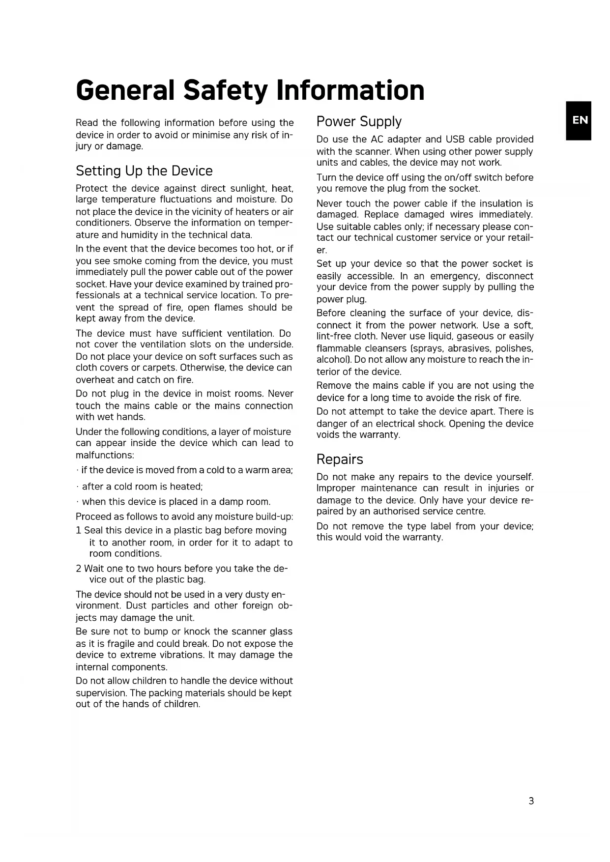
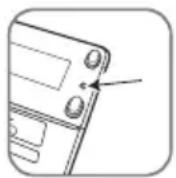
① - STATUS - status indicator - displays the device status
② - ①—On/Off switch—switch the device on/off
③ - ①—Operating status light - Shows the operating mode and device faults
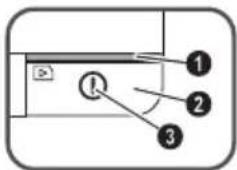
④ Document guide – inserting the document/ remove the tape before using it for the first time
⑤ Document feed slot
6 Grooves for installing the film guide
⑦ Symbol for direction of feed – insert the document into the document feeder with the printed side facing up and one edge as close as possible to the side with this symbol.
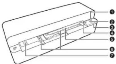
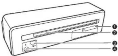
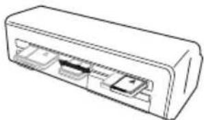
Connections on the Rear Side
① Slot for Memory card (SD, xD, MMC, MS, MS Pro)
② Document outlet
3 Mini USB connection – for connecting a computer (only as a memory card reader) or a digital photo frame
④ - Socket - Port for power supply
Packing Contents
Photo scanner
Calibration sheet
Cleaning sheet for the feed rollers
Cleaning pen for scanner
Adapter for negative film / slides (film guide)
Power supply with exchangeable plugs
USB Cable
Protective cover
Warranty Card
User Manual
Notice

Missing Package Contents
If one of the parts is missing or damaged, please contact your retailer or our customer service.
Connecting power supply
CAUTION!

Mains Voltage at the Site of Installation!
Check whether the mains voltage of your device (indicated on the type label) matches the mains voltage available at the setup location.
1 Insert the small plug of the power supply into the socket on the rear side of your device.
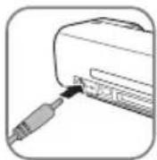
2 Insert the power supply unit into the socket.
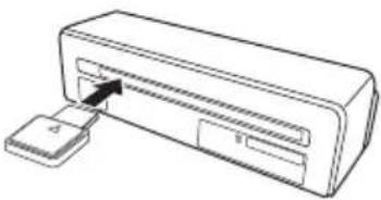
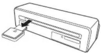
Inserting a Memory Card
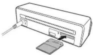
1 Insert a memory card which is not read-only into the appropriate card slot at the rear of the device. Your photo frame supports the following memory cards: SD, xD, MMC, MS, MS Pro.
DANGER!

Inserting a Memory Card!
Only use storage media that are compatible with the device. In order to prevent damage to the card or the unit, please turn off the power before removing or inserting the card.
Never pull out the memory card while the device is accessing it. This could cause data to be damaged or lost.
natural_image
Line drawing of a device with an attached card and cable (no text or symbols)2 Press the button Ⓘ.
3 Wait until the indicator light for the device status is constantly on.
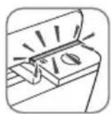
Notice

Control Lamp
If this control lamp flashes, this could stem from one of the following causes.
- no memory card inserted - insufficient memory capacity available on the memory card (less than 1MB)
- The read-only option of the memory card is active
- memory card defective Please note that the initialisation process of a memory card with a capacity of 2GB or more takes longer. The control lamp can blink for up to 20 seconds
Using the digital photo frame
If the device is connected to a compatible digital photo frame, the scanned photos can be transferred directly to the memory of the digital photo frame.
1 Press and hold the Ⓐ key to switch off the device.
2 Connect the digital photo frame to the Mini-USB socket of the device using a USB cable.
3 Switch the device on using the Ⓐ button.
Scanning
Loading Photos
You can insert different types of document into your device. Follow the specifications in the technical data.
You can scan documents using the protective cover to avoid the photo or document being damaged by scratches or creases.
Notice

Scanning documents with the protective cover
If smaller documents are scanned using the protective cover, in certain cases, the automatic cutting off function does not function properly. Either important parts of the image are cut off or too much edge remains around the document. In this case, scan the documents without using the protective cover.
CAUTION!

Unsuitable Documents!
No paper clips, staples, fixing pins or similar may be retained on the documents.
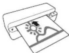
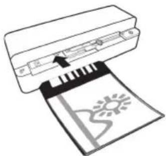
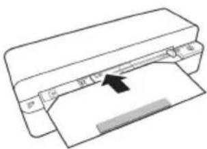
1 Insert a document into the document feeder text side up and the top of the page facing the ① key.
2 Align the document to the left hand edge.
3 Fix the document in place using the document guide on the right hand side. The document guide should lightly touch the documents.
natural_image
Line drawing of a printer with a paper and a sun icon, no text or symbols present4 Push the document horizontally as far into the document feeder until it is automatically fed into the scanner and the scanning process is started. Ensure you do not bend the document. The control lamp ① flashes during the scanning process.
DANGER!

Document Jam!
Do not insert documents into the feeder whilst the device is scanning. This can lead to a paper jam.
5 Wait until the control lamp ① and STATUS are no longer flashing and STATUS is continually on. This means that the scanning process is completed and the data was saved onto the memory card.
DANGER!

Document Jam!
Wait until both control lamps are no longer flashing before you insert the next document in order to prevent a document jam.
6 The file name is assigned according to the DCF (Design Rule for Camera File System) standard.
Notice

Stand-by Mode
If the scanner has not been used for approx. 15 minutes, it automatically switches off.
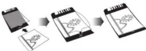
Using the protective cover
1 Open the protective cover and insert the document with the printed side facing up.
flowchart
graph TD
    A["Document"] --> B["Sketching"]
    B --> C["Drawing"]
    style A fill:#f9f,stroke:#333
    style B fill:#ccf,stroke:#333
    style C fill:#cfc,stroke:#333
2 Lay the protective cover into the document feeder with the printed side facing upwards, the closed side of the page (black lines) forward and the page header in the direction of the Ⓐ button.
3 Slide the protective cover horizontally as far into the document feeder until it is automatically fed into the scanner and the scanning process is started. Ensure you do not bend the document. The control lamp ① flashes during the scanning process.
natural_image
Illustration of a printer printing a printed document with a sun icon (no text or symbols)4 Wait until the control lamp ① and STATUS are no longer flashing and STATUS is continually on. This means that the scanning process is completed and the data was saved onto the memory card.
Notice

Removing documents from protective cover
Remove the document from the protective cover after the scanning process in order to avoid the document sticking to the protective cover.
Insert film / slides
Notice

Suitable documents
• 35mm colour negative film
- Unframed slides
• 35mm black/white negative film
• Automatic rotating and mirroring of the photo:
The scanner automatically recognises the orientation of the negativ film when the printed numbers on the edge are in the same orientation as the photo. If the numbering cannot be identified, this function is deactivated.
CAUTION!

Unsuitable Documents!
No glue residue or stickers should be present on the edge of the negative. Only unframed slides can be inserted.
CAUTION!

Damaged negative film ends
If the negative film ends are damaged (not cut evenly, folded), cut the film evenly and removed the folded corners.
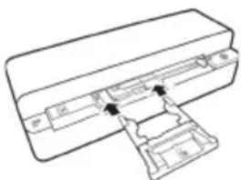
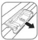
1 Verify that there are not any documents in the document feed. Push the document guide rightmost.
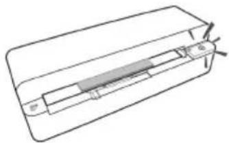
2 Place the film guide on the designated grooves in the document feed.
natural_image
Technical line drawing of a mechanical component with no visible text or symbols3 Carefully slide the film guide all the way into the document feed. Be careful not to damage the metal rails in the film guide.
4 When the film guide is inserted correctly, it snaps into place and the device starts the calibration process.
5 Wait until the control lamps are no longer flashing.
6 Remove the negative film/slides from the protective case/bag.
7 Verify that they are in the correct position for insertion.
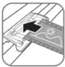
8 Hold the negative film such that the labelling [number] of the negative is legible (not reversed) and the upper side of the image is facing in the direction of the activation key.
9 Insert the negative film / slide into the film guide.
natural_image
Diagram of a solar panel installation with a sun symbol and grid lines (no text or labels)Notice

Handle the negative carefully
Handle the negative with care. If possible, wear cotton gloves.
10 Insert the negative film / slide into the film guide far enough so that it is automatically fed in and the scanning process starts. Be careful not to bend the negative film / slide. The control lamp ① flashes during the scanning process.
Notice

Scanning speed
Due to the higher resolution when scanning negatives / slides, the scanning speed is slower than when scanning photos.
11 Wait until the control lamp ① and STATUS are no longer flashing and STATUS is continually on. This means that the scanning process is completed and the data was saved onto the memory card.
12 Return the scanned negative film / slides to the protective case / bag in order to avoid damage or contamination.
13 The file name is assigned according to the DCF (Design Rule for Camera File System) standard.
14 Remove the film guide after all negativ film / slides are scanned. To do so, pull it out gently and evenly from the document feed.
Notice

Stand-by Mode
If the scanner has not been used for approx. 15 minutes, it automatically switches off.
Cleaning the Scanner Glass
If lines appear on the scanned image or the image is not sharp, you need to clean the scanner glass.
1 Switch the device off.
2 Insert the cleaning pen into the left hand end of the document ejector.
Notice

Instructions for Cleaning
The cleaning pen must be free of any dust.
natural_image
Line drawing of a device with an inserted slot and arrow indicating direction (no text or symbols)3 Move the cleaning pen carefully two or three times to the other end of the document ejector.
natural_image
Line drawing of a rectangular electronic device with internal slots and ports (no text or symbols)4 Move the cleaning pen to the left hand side of the document ejector again and then remove the cleaning pen.
natural_image
Line drawing of a printer with a paper slot inserted into the main body (no text or symbols)Computer Connection
You also use the scanner as a memory card reader in combination with a computer.
Your computer must meet the following minimum requirements:
Operating System
Windows: Windows 2000 · XP · Vista · or later versions · 32 bit or 64 bit
Macintosh: Mass Storage Class Mac OS10.5 or later versions
Connecting to the Computer
The device is Hot-Plug-and-Play capable which means you can link your computer to the device, whilst its running. You do not need to close down your computer to link the device to it.
1 Connect the device to your computer by means of the USB cable.
2 If the USB is working correctly, the device is recognised automatically. A drive letter is assigned to each memory card slot.
Notice

Connecting to an USB hub
If you would like to connect the device to a USB hub = (USB distributor), ensure that the USB hub is connected to the computer before you connect the device to the USB hub.
3 You can access the memory card (drive) and edit the saved files.
Service
Cleaning
DANGER!

Switching off the device!
Switch the device off using the ① before you disconnect the USB cable or the connection to the power supply.
DANGER!

Instructions for Cleaning!
Use a soft, lint-free cloth. Never use liquid or easily flammable cleansers (sprays, abrasives, polishes, alcohol, etc.). Do not allow any moisture to reach the interior of the device. Do not spray the device with any cleaning fluids.
Wipe over the surfaces gently. Be careful that you do not scratch the surfaces.
Cleaning the feed rollers
1 Switch the device off.
2 Press and hold the Ⓘ key until the control lamp Ⓙ light up.
3 The scanner is now in cleaning mode.
4 Push the cleaning sheet into the document feeder.
natural_image
Diagram of a printer with paper and paper holder, showing paper binding (no text or symbols)Notice

Instructions for Cleaning
Observe the direction of feed. The white sponge must be on the upper side.
Do not use any cleaning agents or cleaning fluids. Doing so can permanently damage the feed rollers.
5 The sheet is automatically fed and the cleaning process started. During cleaning, the control lamps ① and STATUS flash.
natural_image
Technical line drawing of a mechanical component or housing with internal channels (no text or symbols)6 After cleaning is complete, the sheet is ejected and the control lamp ① goes out.
Notice

Cleaning sheet for the feed rollers
Store the cleaning sheet in a dust-free location.
Calibrating the Scanner
A calibration of the scanner is necessary if the scanned image looks blurred or has lines that are not on the original. This allows you to adjust and compensate for variations that can occur in the optical component over time by its nature.
1 Clean the scanner glass first before calibrating the scanner.
2 Insert a memory card which is not read-only into the appropriate card slot at the rear of the device.
3 Press the button ①. Wait until the indicator light STATUS is continually on.
4 Place the calibrating sheet in the document feeder with the arrows facing the feed rollers.
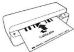
5 The sheet is automatically fed and the calibration process started.
Notice

Calibrating the Scanner
Observe the direction of feed. If the calibration sheet is inserted incorrectly, the calibration process cannot be started.
6 After successful calibration, the sheet is ejected.
Power Cycling
If a problem occurs that cannot be corrected with the instructions in this user manual (see also the help below), follow the steps given here.
1 Press the reset button on the underside of the device with a straightened paper clip.
2 If the problems repeats, please contact our technical customer service or your retailer.
| Problems Solutions | |
| The device cannot be switched on Check that power | supply or the USB cable is connected to the device properly. |
| The device feels warm • After a certain period of operation, the surface reaches approx. 30°C to 45 °C. This is normal. If an unusual smell comes from the device or the surface becomes too hot, disconnect the scanner immediately from the power supply and/or the computer / digital photo frame. | |
| Lines are present on the scanned picture or the image is not sharp | • Check whether the document is dirty or scratched.• Check whether the protective cover used is dirty or scratched.• Clean and calibrate the scanner if it has not been used for a longer period. |
| With scanned images, parts of the image are cut off. | • The scanner is equipped with a function for automatic cutting off of black edges. With small images, the image is only saved without the edge.When using this function, cutting off of important picture information can occur with images with a black background (e.g. night shot). In this case, rotate the image and scan it again. |
| The document is stuck in the feeder • Press the button 1.The document is automatically ejected. | |
| The control lamp STATUS flashes quickly, scanning not possible / memory card is not recognised | Check whether you have used a compatible memory card and whether you have inserted the memory card correctly.Remove the memory card and insert it into the slot againSwitch any active read-only options on the memory card off.Make sure the memory card is not damaged.Check the available memory space on the memory card. If the available space is less than 1MB, the scanning process cannot take placeCheck the file format of the memory card Only memory cards in the FAT16 or FAT32 file format can be used.Check whether the next document was inserted too quickly.When scanning several documents, wait until the data transfer of the first scan has ended (status lamp continuously on)Check the document length (see technical data) |
| Transfer to a digital photo frame is not working | This function is only available with certain photo frames. |
EN
Appendix
Technical Data
Type ...... Color Contact Image Sensor (CIS)
Dimensions (L × H × W).... 158 × 45 × 55 mm
Weight.... 0,23 kg
Mains Connection .... Input: 100 - 240 V \~ (±10%) / 50 - 60 Hz .... Output: 5V = / 1A
Power Consumption
Operation....<9W
Recommended Ambient.... 15–35°C
Relative Humidity 20–70% (non-condensing)
Scanner
Input format.... 48 bit colour
Output format.... 24-Bit
Maximum hardware resolution, photos.... 300×300 dpi
Maximum hardware resolution film/slides....1200×1200 dpi
Document Feed Slot
Maximum thickness of cheque cards/plastic cards ....1 mm
Paper formats supported Minimum (B × L) 42 × 20 mm
Maximum (B × L)....105 × 304,8 mm
Paper Weight 50 - 105 g/m²
Supported film formats 35mm colour negative film .....6 photos, unframed 35mm transparency slides ....unframed Film type detection [colour, B/W, slide]..automatic
Computer Connection
Connection Type ....Compatible with ....USB 2.0 High Speed
Power supply
Model No....ADS-5N-06 05005G
Manufacturer....SHENZHEN HONOR ELECTRONIC CO.,LTD.
Technical specifications subject to change without notice.
AgfaPhoto is used under license of Agfa-Gevaert NV & Co. KG or Agfa-Gevaert NV. Neither Agfa-Gevaert NV & Co KG nor Agfa-Gevaert NV manufacture this product or provide any product warranty or support.
For service, support and warranty information, contact the distributor or manufacturer.
Contact: AgfaPhoto Holding GmbH, www.agfaphoto.com
Manufacturer: Sagemcom,
www.sagemcom.com

The CE symbol confirms conformity with the EU directives that apply to the device.
Preservation of the environment as part of a sustainable development logic is an essential concern of AgfaPhoto. The desire of AgfaPhoto is to operate systems observing the environment. The desire of AgfaPhoto is to operate systems observing the environment and consequently it has decided to integrate environmental performances in the life cycle of this products, from manufacturing to commissioning use and elimination.

Packaging: The presence of the logo (green dot) means that a contribution is paid to an approved national organisation to improve package recovery and recycling infrastructures to facilitate. Please respect the sorting rules set up locally for this kind of waste.
Batteries: If your product contains batteries, they must be disposed of at appropriate collection points.

Product: The crossed-out waste bin stuck on the product means that the product belongs to the family of electrical and electronic equipment. In
this respect, the European regulations ask you to dispose of it selectively;
- At sales points in the event of the purchase of similar equipment.
- At the collection points made available to you locally(drop-off centre, selective collection, etc.).
In this way you can participate in the re-use and upgrading of Electrical and Electronic Equipment Waste, which can have an effect on the environment and human health.
The paper and cardboard packaging used can be disposed of as recyclable paper. Have the plastic wrapping and Styrofoam packaging recycled or dispose of it in the non-recyclable waste, depending on the requirements in your country.
Trademarks: The references mentioned in this manual are trademarks of the respective companies. The lack of the trademarks ® and ™ does not justify the assumption that these dedicated terminologies are free trademarks. Other product names used herein are for identification purposes only and may be trademarks of their respective owners. AgfaPhoto disclaims any and all rights in those marks.
The reproduction of certain documents (e.g. by scanning, printing, copying) is prohibited in many countries. The list of such documents below is not intended to be complete, it only offers a general overview. In case of doubt, consult your legal advisor.
- Passports (personal identification)
- Entrance and exit visa papers (immigration papers)
· Military service documents
· Bank notes, travel checks, payment orders - Postage stamps, tax stamps (stamped or un-stamped)
· Loan papers, certificates of deposit, bonds
· Documents protected by copyright
Follow the statutory regulations of your country with regard to the legal validity of fax transmissions—particularly in connection with the validity of signatures, meeting delivery deadlines or disadvantages resulting from the loss of quality in the transmission, etc.
Take care to maintain the statutory regulations of your country regarding telecommunications secrecy and data privacy.
Neither AgfaPhoto nor its affiliates shall be liable to the purchaser of this product or third parties for damages, losses, costs, or expenses incurred by the purchaser or third parties as a result of accident, misuse, or abuse of this product or unauthorized modifications, repairs, or alterations to this product, or failure to strictly comply with AgfaPhoto operating and maintenance instructions.
AgfaPhoto shall not be liable for any damages or problems arising from the use of any options or any consumable materials other than those designated as original AgfaPhoto products or AgfaPhoto approved products.
AgfaPhoto shall not be held liable for any damage resulting from electromagnetic interference that occurs from the use of any interface cables other than those designated as AgfaPhoto products.
All rights reserved. No part of this publication may be reproduced, stored in a retrieval system or transmitted in any form or by any means, electronic, mechanical, photocopying, recording, or otherwise, without the prior written permission of AgfaPhoto. The information contained herein is designed only for use with this product. AgfaPhoto is not responsible, if this information is applied to other devices.
This user manual is a document that does not represent a contract.
Errors, printing errors and changes are reserved.
Copyright © 2010
Introduzione
Stimato cliente,
natural_image
Diagram of a device with an attached card and cable, showing no text or symbolsnatural_image
Illustration of a printer with a printed document featuring a sun and landscape icon (no text or symbols)natural_image
Diagram of a printer printing a printed document with a stylized logo (no text or symbols present)natural_image
Technical line drawing of a mechanical assembly with no visible text or symbolsnatural_image
Diagram of a solar panel installation with an arrow indicating direction (no text or symbols)Nota

natural_image
Line drawing of a rectangular device with an arrow pointing to its internal structure (no text or symbols)Macintosh: Mass Storage Class Mac OS10.5 o versioni successive
Inhoud verpakking
Fotoscanner
Kalibratiepagina
natural_image
Line drawing of a device with an attached cable and a card slot (no text or symbols)2 Drukoptoets Ⓘ.
natural_image
Illustration of a printer with a paper and sun icon (no text or symbols)flowchart
graph TD
    A["Document"] --> B["Sketching"]
    B --> C["Drawing"]
    C --> D["Final Drawing Pattern"]
natural_image
Line drawing of a printer with a printed paper showing a sunburst graphic (no text or symbols)natural_image
Technical line drawing of a mechanical component with internal parts and arrows indicating assembly or movement (no text or symbols)natural_image
Diagram showing a device with a sun icon and grid lines, no readable text or symbols presentOpmerking

natural_image
Line drawing of a printer with an inserted slot and paper clip (no text or symbols)natural_image
Line drawing of a rectangular electronic device with internal ports (no text or symbols)natural_image
Line drawing of a printer with an open slot and paper clip inserted (no text or symbols)Computeraansluiting
natural_image
Line drawing of a printer with paper and a paper holder, no text or symbols presentOpmerking

natural_image
Pure technical line drawing of a mechanical component without any text, numbers, or symbolsnatural_image
Line drawing of a device with an open port and a separate card slot, no text or symbols presentnatural_image
Line drawing of a printer with a printed paper and sun icon (no text or symbols)natural_image
Illustration of a printer printing a printed document (no text or symbols visible)natural_image
Diagram of a solar panel installation with a sun symbol and grid lines (no text or labels)Nota

natural_image
Line drawing of a rectangular device with an arrow pointing to its internal structure, no text or symbols present.natural_image
Line drawing of a rectangular electronic device with three ports (no text or symbols)natural_image
Line drawing of a printer with an open slot and arrow indicating insertion (no text or symbols)natural_image
Diagram of a printer with paper and paper holder, showing paper layout and printer edge (no text or symbols)Nota

natural_image
Technical line drawing of a mechanical component or housing with internal channels (no text or symbols)natural_image
Line drawing of a device with an attached card and cable, no text or symbols presentnatural_image
Line drawing of a printer with a printed paper and a sunburst graphic (no text or symbols)natural_image
Illustration of a printer printing a printed document (no text or symbols visible)natural_image
Technical line drawing of a mechanical component with no visible text or symbolsnatural_image
Diagram of a solar panel installation with a black arrow indicating direction (no text or symbols)Indicação

natural_image
Line drawing of a device with an open port and a small rectangular component inserted (no text or symbols)natural_image
Line drawing of a rectangular electronic device with internal ports (no text or symbols)natural_image
Line drawing of a printer with an open slot and paper clip inserted (no text or symbols)Porta do computador
natural_image
Diagram of a printer with paper and paper holder, showing paper binding (no text or symbols)Indicação

natural_image
Pure technical line drawing of a mechanical component without any text, numbers, or symbolsUttag på baksidan
natural_image
Line drawing of a device with an attached cable and a card slot (no text or symbols)natural_image
Line drawing of a printer with a printed paper featuring a sun and wave design (no text or symbols)flowchart
graph LR
    A["Document"] --> B["Trees Rotation"]
    B --> C["Tree Outline"]
natural_image
Diagram of a printer printing a printed circuit board (no text or symbols visible)natural_image
Technical line drawing of a mechanical component with internal parts and arrows indicating assembly (no text or symbols)natural_image
Diagram of a solar panel installation with a black arrow indicating direction (no text or symbols)Anvisningar

natural_image
Line drawing of a device with an inserted slot and arrow indicating direction (no text or symbols)natural_image
Line drawing of a rectangular electronic device with three ports (no text or symbols)natural_image
Line drawing of a printer with an open slot and a small rectangular object inserted (no text or symbols)Datoranslutning
natural_image
Diagram of a printer with paper and paper holder, showing paper layout and printer tip (no text or symbols)Anvisningar

natural_image
Technical line drawing of a mechanical component or housing with internal channels (no text or symbols)Obsah dodávky
Skener fotografií
Kalibrační list
natural_image
Diagram of a device with an open port and cable inserted, showing no text or symbolsnatural_image
Illustration of a printer with a printed document featuring a sun and mountain graphic (no text or symbols)flowchart
graph TD
    A["Document"] --> B["Sketching"]
    B --> C["Drawing"]
    C --> D["Final Drawing Pattern"]
natural_image
Illustration of a printer with a paper strip and a sun icon, no text or symbols presentnatural_image
Technical line drawing of a mechanical assembly with no visible text or symbolsnatural_image
Diagram of a solar panel installation with a black arrow indicating direction (no text or symbols)Poznámka

natural_image
Line drawing of a printer with an attached paper clip (no text or symbols)natural_image
Line drawing of a rectangular electronic device with internal ports (no text or symbols)natural_image
Line drawing of a device with an arrow pointing to a component (no text or symbols)natural_image
Diagram of a printer with paper and paper being inserted, showing no text or symbolsPoznámka

Návod k čistění
natural_image
Technical line drawing of a mechanical component with no visible text or symbols5 List je automaticky vtažen a postup kalibrace se spustí.
Poznámka

Kalibrace skeneru
A csomag tartalma
Fényképszkenner
Kalibráló lap
natural_image
Line drawing of a device with an open port and a separate slot, no text or symbols presentnatural_image
Line drawing of a printer with a printed image showing sun, wind, and landscape graphics (no text or symbols)flowchart
graph TD
    A["Receipt"] --> B["Document Icon"]
    B --> C["Packaging Pattern"]
    C --> D["Final Packaging"]
natural_image
Illustration of a printer printing a printed document with a sun icon (no text or symbols)natural_image
Technical line drawing of a mechanical component with internal parts and arrows indicating assembly (no text or symbols)natural_image
Diagram of a solar panel installation with a black arrow indicating direction (no text or symbols)Megjegyzés

natural_image
Line drawing of a rectangular device with an inserted slot and arrow pointing to its side (no text or symbols)natural_image
Line drawing of a rectangular electronic device with internal ports (no text or symbols)natural_image
Line drawing of a printer with a paper clip inserted into the cover (no text or symbols)natural_image
Diagram of a printer with paper and paper holder, showing paper size and orientation arrows (no text or symbols)Megjegyzés

Návod na čistenie
Sledujte smer naberania. Biela hubka musí byt' na hornej strane.
natural_image
Technical line drawing of a mechanical component or housing with internal channels (no text or symbols)Przyłącza z tyłu
natural_image
Line drawing of a device with an attached port and cable, showing no text or symbolsnatural_image
Line drawing of a printer with a paper and sun icon (no text or symbols)flowchart
graph LR
    A["Document Submission"] --> B{Approval}
    B --> C["Output Tree-like Diagram"]
    C --> D["Final Output"]
natural_image
Illustration of a printer printing a printed document with a sun icon (no text or symbols)natural_image
Technical line drawing of a mechanical component with internal parts and arrows indicating assembly or movement (no text or symbols)natural_image
Diagram of a solar panel installation with a black arrow indicating direction (no text or symbols)Wskazówku

natural_image
Line drawing of a rectangular device with an arrow pointing to its side panel (no text or symbols present)natural_image
Line drawing of a rectangular electronic device with internal ports (no text or symbols)natural_image
Line drawing of a printer with an open slot and paper clip inserted (no text or symbols)natural_image
Line drawing of a printer with a paper slot and arrow indicating print direction (no text or symbols)Wskazówku

Návod na čistenie
Sledujte smer naberania. Biela hubka musí byt' na hornej strane.
natural_image
Pure technical line drawing of a rectangular mechanical component with internal channels (no text or symbols)Continut ambalaj
Scanner foto
Foaie de calibrare
natural_image
Line drawing of a device with an attached port and cable, no text or symbols presentnatural_image
Line drawing of a printer with a printed image showing a sun and mountain landscape (no text or symbols)natural_image
Illustration of a printer with a printed circuit board (no text or symbols visible)natural_image
Diagram showing a mechanical component with a black arrow pointing to a textured surface and sun icon (no text or symbols)Indicatie

natural_image
Line drawing of a printer with an open slot and a separate clip inserted (no text or symbols)natural_image
Line drawing of a rectangular electronic device with internal ports (no text or symbols)natural_image
Line drawing of a printer with an open slot and paper clip inserted (no text or symbols)Conexiune computer
natural_image
Diagram of a printer with paper and paper holder, no text or symbols presentIndicatie

natural_image
Technical line drawing of a mechanical component or housing with internal components (no text or symbols)Minim (B × L).... 42 × 20 mm
Maxim (B × L)....105 × 304,8 mm
Greutate hârtie....50 – 105 g/m²
Formate de film suportate
Pelicule negative color 35mm...poze neînrămate 6
Obsah dodávky
Skener fotografií
Kalibračný list
Čistiaci list naberacieho valčeka
Čistiace pero skenera
Adaptér na negativny film / listy (vodidlo)
natural_image
Line drawing of a device with an attached card and cable, no text or symbols presentnatural_image
Illustration of a printer with a printed paper showing a sun and mountain graphic (no text or symbols)natural_image
Diagram of a printer with an open circuit board and a sun icon on the cover (no text or symbols)natural_image
Technical line drawing of a mechanical assembly with no visible text or symbolsnatural_image
Diagram of a solar panel installation with a black arrow indicating direction (no text or symbols)Poznámka

natural_image
Line drawing of a rectangular device with an inserted slot and arrow indicating direction (no text or symbols)natural_image
Line drawing of a rectangular electronic device with internal ports (no text or symbols)natural_image
Line drawing of a printer with an open slot and arrow indicating insertion (no text or symbols)natural_image
Diagram of a printer with paper and paper holder, no text or symbols presentPoznámka

Návod na čistenie
Sledujte smer naberania. Biela hubka musí byt' na hornej strane.
natural_image
Technical line drawing of a mechanical component or housing with internal channels (no text or symbols)Ambalaj içeriği
Fotoğraf tarayıcısı
Kalibrasyon sayfası
natural_image
Line drawing of a device with an attached card and cable (no text or symbols)2 Ⓐ tuşuna basıniz.
natural_image
Line drawing of a printer with a printed paper showing a sunburst graphic (no text or symbols)flowchart
graph LR
    A["Document"] --> B["Approval"]
    B --> C["Drawing with floral pattern"]
    C --> D["Final Drawing"]
natural_image
Illustration of a printer printing a printed document (no text or symbols visible)natural_image
Line drawing of a rectangular device with an inserted slot and a separate slot inserted into the top portion (no text or symbols)natural_image
Line drawing of a device with an open slot and a small rectangular block inserted (no text or symbols)Asgari (B × L).... 42 × 20 mm
Azami (B × L)....105 × 304,8 mm
natural_image
Line drawing of a device with an open port and a separate slot, no text or symbols presentnatural_image
Line drawing of a printer with a printed image showing a sun and mountain landscape (no text or symbols)natural_image
Illustration of a printer printing a printed document with a stylized sun icon (no text or symbols)natural_image
Technical line drawing of a mechanical component with no visible text or symbolsnatural_image
Line drawing of a rectangular device with an inserted slot and arrow pointing to the interior (no text or symbols)natural_image
Line drawing of a rectangular electronic device with internal ports (no text or symbols)natural_image
Line drawing of a printer with an open slot and paper clip inserted (no text or symbols)Συνδεσιμότητα Η/Υ
natural_image
Diagram of a printer with paper and paper holder, showing paper binding (no text or symbols)Οδηγία

natural_image
Technical line drawing of a mechanical component or housing with internal channels (no text or symbols)Комплект поставки
Фотосканер
Калибровочный лист
natural_image
Line drawing of a device with an attached card and cable (no text or symbols)2 Нажмите кнопку Ⓘ.
natural_image
Line drawing of a printer with a printed document featuring a sun and mountain graphic (no text or symbols)natural_image
Line drawing of a printer with an arrow indicating print direction (no text or symbols)natural_image
Technical line drawing of a mechanical component with internal parts and arrows indicating assembly or movement (no text or symbols)natural_image
Diagram of a mechanical component with arrows indicating direction, no visible text or symbolsЗамечания

natural_image
Line drawing of a rectangular device with an inserted slot and a separate slot, no text or symbols present.natural_image
Line drawing of a rectangular electronic device with internal ports (no text or symbols)natural_image
Line drawing of a printer with an open slot and a small rectangular object inserted (no text or symbols)natural_image
Diagram of a printer with paper and paper holder, no text or symbols presentЗамечания

natural_image
Pure technical line drawing of a mechanical component without any text, numbers, or symbolsAgfaPhoto is used under license of Agfa-Gevaert NV & Co. KG or Agfa-Gevaert NV. Neither Agfa-Gevaert NV & Co. KG nor Agfa-Gevaert NV manufacture this product or provide any product warranty or support. For service, support and warranty information, contact the distributor or manufacturer.
AS1150
Booklet
253354001-A