ST 3262 P - Snow blower STIGA - Free user manual and instructions
Find the device manual for free ST 3262 P STIGA in PDF.

| Product type | Snow thrower |
| Brand | STIGA |
| Model | ST 3262 P |
| Fuel | Unleaded gasoline (do not use 2-stroke mixture) |
| Engine | 4-stroke, Briggs & Stratton (recommended spark plug LDF7TC) |
| Oil capacity | 0.6 liter (oil SAE 5W30-10W40, API SF/SG/SH) |
| Number of speeds | 5 forward, 2 reverse |
| Starting | Manual (recoil starter) or electric (220/230 V with grounded outlet) |
| Tire pressure | 1.2 bar |
| Working width | Not specified in the manual (estimate: about 55-65 cm) |
| Discharge orientation | Manually adjustable control lever |
| Discharge deflector | Height adjustable |
| Skid shoes | Adjustable: 3 mm (flat ground) to 30 mm (gravel) |
| Safety system | Stop switch, engine stop in OFF position, lever disengagement, clearing tool |
| Maintenance - Oil change | First oil change after 2 hours, then every 20 hours |
| Maintenance - Spark plug | Check/replace every 100 hours |
| Maintenance - Lubrication | Every 10 hours: bearings, belt tension arm |
| Wear parts | Belts, auger, tires, shear bolts, cables |
| Repairability | Genuine parts available from dealer or authorized center; shear bolts replaceable by the user |
| Warranty | Manufacturer's warranty on material defects and manufacturing faults (excluding wear parts) |
Frequently Asked Questions - ST 3262 P STIGA
User questions about ST 3262 P STIGA
0 question about this device. Answer the ones you know or ask your own.
Ask a new question about this device
Download the instructions for your Snow blower in PDF format for free! Find your manual ST 3262 P - STIGA and take your electronic device back in hand. On this page are published all the documents necessary for the use of your device. ST 3262 P by STIGA.
USER MANUAL ST 3262 P STIGA
natural_image
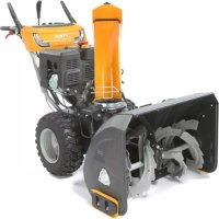
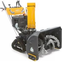
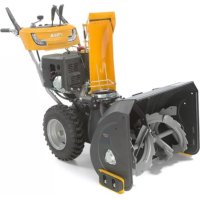
Exterior view of a snowman drive with visible blade and shank (no text or symbols)STIGA
ST 3256 P
ST 3262 P
Type ST 601
SNÖSLUNGA
LUMILINKO
SNESLYNGE
SN∅SLYNGE
SCHNEERÄUMER
SNOW THROWER
CHASSE-NEIGE
SPAZZANEVE
ODŚNIEŻARKA
СНЕГООЧИСТИТЕЛЬ
SNĚHOVÁ FRÉZA
HÓMARÓ
SNEŽNI PLUG
SNEHOVÁ FRÉZA
LUMEPUHUR
SNIEGO VALYTUVAS
SNIEGA TİRİTÄJS
BRUKSANVISNING OCH UNDERHÅLL......SV
KÄYTTÖOPAS....FI
INSTRUKTIONSMANUAL......DA
BRUKSANVISNING-VEDLIKEHOLD......NO
GEBRAUCHSANWEISUNG......DE
INSTRUCTION MANUAL......EN
MANUEL D'UTILISATION......FR
MANUALE DI ISTRUZIONI......IT
INSTRUKCJE OBSŁUGI....PL
natural_image
Two identical tire illustrations labeled A and B, showing different tire profiles (no text or symbols beyond labels)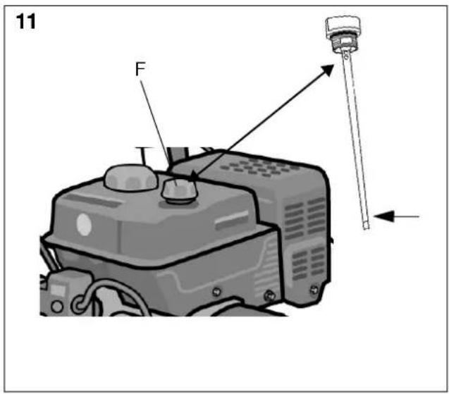
1 ALLMÄNT

4.7 ANSLUTNINGSSLADD - ELSTART (T) (CRYSTAL)
4.8 STARTHANDTAG (U)
4.14 KOPPLINGSHANDTAG - DRIVNING (N)

5.5 START AV MOTOR (MED ELSTART) (CRYSTAL), SE FIG. 1

4.4 BRÆNDSTOFHANE (M)

4.6 STOPAFBRYDER (S)
Bruges til at stoppe motoren. Afbryderen har to positioner:

4.14 KOBLINGSHÄNDTAG - FREMDRIFT (N)

5.5 START AF MOTOR (MED ELSTART) (CRYSTAL), SE FIG. 1

7.5 UDSKIFTNING AF SIKRINGSBOLTE (1:W)
2.4 VEDLIKEHOLD OG OPPBEVARING
3.5 INNSTILLINGSVEIV, SE FIG. 8
4.9 OLEPÄFYLLINGSDEKSEL/OLJEPINNE (P)

4.14 KOPLINGSHÄNDTAK - FREMDRIFT (N)

4.16 INNSTILLINGSVEIV (E)
5.5 START AV MOTOR (MED ELSTART) (CRYSTAL), SE FIG. 1

6.1 VEDLIKEHOLDSPLAN
7.5 SKIFTE AV SIKKERHETSBOLTER (1:W)
Warnung.
4.5 STARTKNOPF - ELEKTROSTART (R) (CRYSTAL)
This symbol indicates CAUTION. Serious personal injury and/or damage to property may result if the instructions are not followed carefully.
1.1 SYMBOLS
The following symbols appear on the machine. They are there to remind you of the care and attention required in use. This is what the symbols mean:

Warning.

Read and understand the owner's manual before using this machine.

Disconnect the spark plug wire, and consult technical literature before performing repairs or maintenance.

Danger - rotating fan.

Danger - rotating auger.

Keep hands out of discharge chute.

Keep hands and feet away from rotating parts.
Risk of burns.
Keep bystanders at a safe distance from the machine.
Never point the discharge chute towards bystanders.

Use hearing protection.
1.2 REFERENCES
1.2.1 Figures
The figures in these instructions for use are numbered 1, 2, 3, etc.
Components shown in the figures are marked A, B, C, etc.
A reference to component C in figure 2 is written as follows:
"See fig. 2:C." or simply "(2:C)"
1.2.2 Headings
The headings in these instructions for use are numbered in accordance with the following example:
“1.3.1 General safety checks” is a subheading to “1.3 Safety checks” and is included under this heading.
When referring to headings, only the number of the heading is normally specified. E.g. "See 1.3.1".
2 SAFETY INSTRUCTIONS
2.1 GENERAL
- Please read through these instructions carefully. Learn all the controls and the correct use of the machine.
- Never allow children or anyone who is not familiar with these instructions to use the snow thrower. Local regulations may impose restrictions as regards the age of the driver.
- Never use the machine if others, particularly children or animals, are in the vicinity.
- Remember that the driver is responsible for accidents that happen to other people or their property.
- Be careful not to trip or fall, especially when reversing the machine.
- Never use the snow thrower under the influence of alcohol or medication and if you are tired or ill.
2.2 PREPARATIONS
- Check the area to be cleared and remove any loose or foreign objects.
- Disengage all controls before starting the engine.
- Never use the snow thrower unless properly dressed. Wear footwear that improves your grip on a slippery surface.
- Warning – Petrol is highly inflammable.
a. Always store petrol in containers that are made especially for this purpose.
b. Only fill or top up with petrol outdoors, and never smoke when filling or topping up.
c. Fill with petrol before starting the engine. Never remove the filler cap or fill with petrol while the engine is running or still warm.
d. Screw the filler cap on tightly and wipe up any spilt petrol.
- Adjust the height of the auger housing to ensure it stays above gravel paths.
- Never, under any circumstances, make adjustments while the engine is running (unless otherwise specified in the instructions).
- Allow the snow thrower to adjust to the outdoor temperature before using it.
- Always use protective goggles or a visor during use, maintenance and service.
2.3 OPERATION
- Keep hands and feet away from rotating parts. Always avoid the discharge chute opening.
- The snow thrower must never be used to remove anything but snow
- Be careful when driving on or crossing gravel paths, pavements and roads. Be aware of hidden dangers and traffic.
- Never direct the discharge chute towards a public road or traffic.
-
If the snow thrower hits a foreign object, stop the engine, disconnect the spark plug cable and carefully inspect the machine for damage. Repair the damage before using the machine again.
-
If the machine starts vibrating abnormally, stop the engine and look for the cause. Vibration is normally a sign of something wrong.
- Stop the engine and disconnect the spark plug cable: a. If the machine steers away from the driving position. b. If the auger housing or discharge chute is blocked and must be cleaned. c. Before beginning repairs or adjustments.
• Always make sure the rotating parts have stopped and all the controls are disengaged before cleaning, repairing or inspection. - Before leaving the machine unattended, disengage all the controls, put it into neutral gear, stop the engine and set the stop switch in position “OFF”.
- Never run the engine indoors except when taking it in and out of its place of storage. In this case ensure the door to the storage place is open. Exhaust fumes are toxic.
- Never drive across a slope. Move from the top down, and from the bottom to the top. Be careful when changing direction on a slope. Avoid steep slopes.
- Never operate the machine with insufficient protection or without the safety devices in place.
- Existing safety devices must not be disconnected or disengaged.
- Do not alter the engine's regulator setting and do not race the engine. The possibility of personal injury increases when the engine is run at high revs.
- Never use the snow thrower near enclosures, cars, windowpanes, slopes etc. without properly setting the discharge chute deflector.
• Always keep children away from areas to be cleared. Get another adult to keep the children under supervision. - Do not overload the machine by driving it too fast.
• Take care when reversing. Look behind you before and during reversing to check for any obstacles. - Never point the discharge chute towards bystanders. Do not allow anyone to stand in front of the machine.
- Disengage the auger when the snow thrower is to be transported or is not in use. Do not drive too fast on slippery surfaces when transporting.
- Only use accessories that are approved by the machine's manufacturer.
- Never drive the snow thrower in bad visibility or without satisfactory lighting.
• Always ensure you have a good balance and a tight grip on the handle. - Never use the snow thrower on a roof.
- Do not touch engine components because they are warm during use. Risk of burn injuries.
2.4 MAINTENANCE AND STORAGE
- Tighten all nuts and screws so that the machine is in safe working condition. Check the shear bolts regularly.
• Always use genuine spare parts. Non-genuine spare parts can entail a risk of injury, even if they fit the machine. - Never store the machine with petrol in the tank in buildings where the fumes can come into contact with open flames or sparks.
- Allow the engine to cool before putting the machine in store.
-
Before a long storage, check the instructions for recommendations.
-
Replace damaged warning and instruction stickers.
- Let the engine run a couple of minutes with the auger connected after use. This prevents the auger from freezing solid.
3 ASSEMBLY
Note: Instructions to the left and right sides start from the driving position behind the snow thrower.
3.1 CONTENTS - OUTER PACKING
The packing contains details to be assembled according to the table below:
| Detail Item Fig. Number | |||
| Snow thrower 1 1 | |||
| Adjustment lever T 8 1 | |||
| Gear lever H 9 1 | |||
| Discharge chute | D 7 | 1 | |
| Handle | X 2 | 1 | |
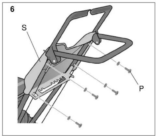
| Front panel | S 6 | 1 | |
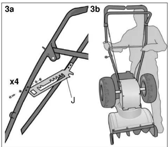
| Gear panel (Cube) | J | 3a | 1 |
| Instruction manual | - | - | 1 |
| Assembly kit, containing details according to the table below | - | - | 1 |
The assembly kit is delivered in two bags and contains the following parts:
| Detail | Item | Fig. | Number |
| Screw for the gear panel (Cube) | 3a | 4 | |
| Washer for the gear panel (Cube) | 3a | 8 | |
| Nut for the gear panel (Cube) | 3a | 4 | |
| Screw for the handle | A | 4-5 | 4 |
| Square washers for the handle | B | 4 | 2 |
| Washers for the handle | C | 5 | 2 |
| Washers for the adjustment lever | Z | 8 | 2 |
| Locking pin for the adjustment lever | G | 8 | 1 |
| Adjustment lever handle | Y | 8 | 1 |
| Washer for adjustment lever handle | Q | 8 | 1 |
| Screw for adjustment lever handle | R | 8 | 1 |
| Screw for the front panel | P | 6 | 4 |
| Short screw for the gear lever | I | 9 | 1 |
| Locking nut for the screw above | - | 9 | 1 |
| Long screw for the gear lever | V | 9 | 1 |
| Locking nut for the screw above | W | 9 | 1 |
| Carriage pieces | E | 7 | 3 |
| Screw for carriage pieces | - | 7 | 6 |
| Washers for carriage pieces | - | 7 | 6 |
| Nuts for carriage pieces | - | 7 | 6 |
In addition, the following Accessories/tools are supplied:
| Accessorie/tool Item Fig. Number | |||
| Chute clearing tool G 1 1 | |||
| Extra break bolts for spare | W | 1 2 | |
| Spark plug key | - | - | 1 |
| Allen key | - | - | 1 |
| Ignition key, spare | 2 |
3.2 UNPACKING
- Remove all loose items from the carton.
- Cut the four corners of the carton and let the sides fall down.
- Roll the snow thrower from the carton.
3.3 HANDLE
The procedure requires two persons as the handle must be held in position during the assembly.
- Position the snow thrower on its auger.
- Cube:
Assemble the gear panel. See fig. 3a.
Crystal:
Loosen both wheels from their axis and move them out about 10 cm from the snow thrower.
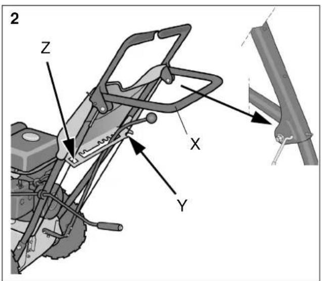
- See fig. 3b. Held the handle straight above the snow thrower and hook on the wires into their respective handle. Note the wire locations through the recess (Z) and into the recess (Y). Fig. 2 shows the wire locations when the assembly is finished.
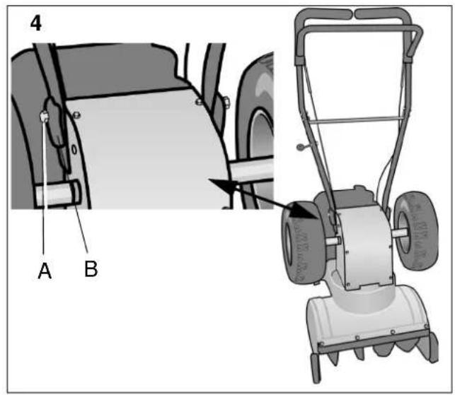
- See fig. 4. Assemble the upper screw (A) with square washer (B) through the handle and screw into the snow thrower at both sides without fastening.
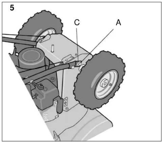
- See fig. 5. Fold carefully up the handle forwards and assemble the two lower screws (A) with washers (C) at both sides.
- Check that the wires are located according to (Z) and (Y) in fig. 2.
- Tighten the four screws (A).
- Push the wheels into place and fix them to the axis.
- Position the snow thrower on its wheels.
- Assemble the front panel in the four holes in the handle and fasten it with four screws with washers from below. See fig. 6.
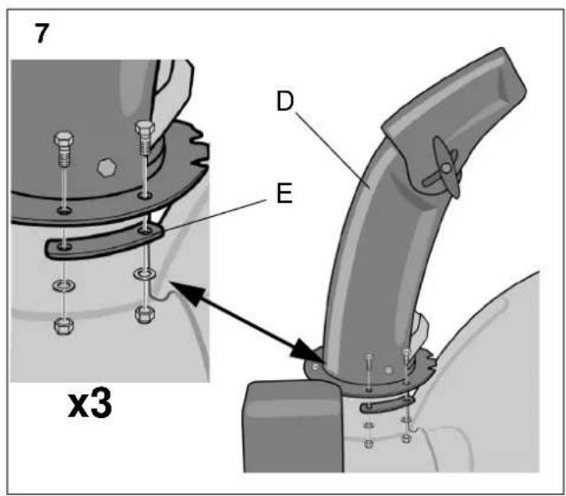
3.4 SNOW DISCHARGE CHUTE, SEE FIG. 7
- Place the discharge chute (D) on the flange.
- Mount the three carriage pieces (E) with two screws each.
- Tighten properly.
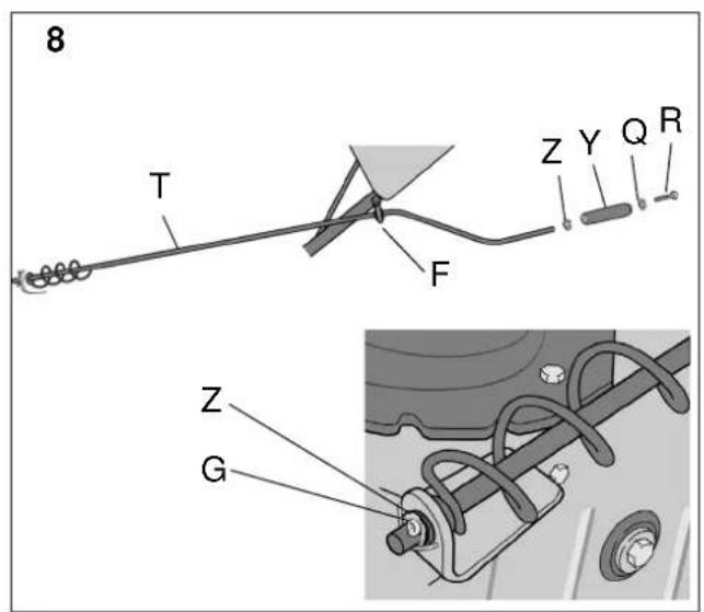
3.5 ADJUSTMENT LEVER, SEE FIG. 8
- Insert the adjustment lever through the cycbolt (F) from the front.
- Insert the end of the shaft in the plastic bushing and adjust the worm gear to the cut out in the snow discharge chute.
- Install the washer (Z) and lock with the locking pin (G).
- Install the washer (Z), lever handle (Y) with screw (R) and washer (Q).
- Check the snow discharge chute by turning it between its end positions. The now discharge chute shall rotate freely.
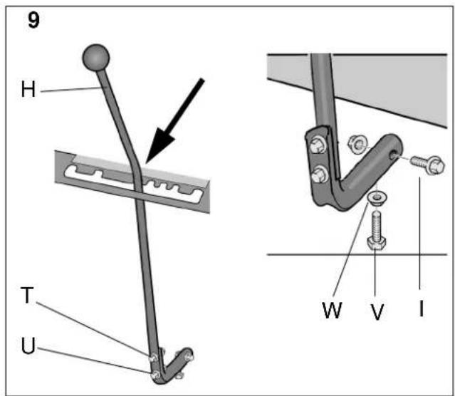
3.6 GEAR LEVER, SEE FIG. 9
Assemble the gear lever to the gearbox shaft as follows:
- Set up the machine on the auger housing and set the gear lever (H) in the first gear forwards. See fig. 9.
- Assemble the screw (I) through the angle joint and shaft. Tighten the screw.
- Tighten the screws (U) between the gear lever and the angle joint.4.
- Tighten the screw (V) until the gear lever remains in the gear positions in the panel plate. Secure by tightening the locking nut (W)
- Set down the machine on its wheels.
3.7 CHECKING THE CONTROL WIRES
The control wires might need adjusting before using the snow thrower for the first time.
See "7.4" below.
3.8 TYRE PRESSURE
Check the air pressure in the tyres. See ""Tyre pressure" på sidan 49".
4 CONTROLS

The motor is equipped with a protection grid. The motor may never be started without the grid fitted or with a defect grid.
See fig. 1.
4.1 THROTTLE (K)
Controls the engine's revs. The throttle has two positions:

- Full throttle

- Idling.
4.2 CHOKE (L)
Used when starting a cold engine. The choke has two positions:

Up - the choke is closed (for cold starting)
To the left - the choke is open
4.3 PRIMER (J)

Pressing the rubber prime-starter squirts fuel into the carburettor intake pipe to make it easier to start a cold engine.
4.4 FUEL COCK(M)

The fuel cock opens the fuel supply to the carburettor. The fuel cock shall always be closed when the machine is not in use.
To the left - open.
Up - closed.
4.5 START BUTTON – ELECTRICAL START (R) (CRYSTAL)
Activates the electric starting motor.
4.6 STOP SWITCH (S)
Used to stop the engine. The switch has two positions:

Pulled out-OFF - The engine stops, engine can not start.
Pushed in-ON - The engine can be started, engine running.
4.7 ELECTRIC CABLE – ELECTRICAL START (T) (CRYSTAL)
Supplies power to the starting motor. Connect the cable to a 220/230 volt earthed socket via an earthed extension lead. It is wise to use an earth fault breaker.
4.8 STARTING HANDLE (U)
Manual cord start with rewinding.
4.9 OIL FILLER CAP/OIL DIPSTICK (P)
For filling and checking the oil level in the engine.
4.10 FILLER CAP (C)

For filling with petrol.
4.11 OIL DRAINING PLUG (Q)
For draining the old engine oil when changing the oil.
4.12 SPARK PLUG PROTECTION (F)
The protection is easily removable by hand. The spark plug is located under the protection.
4.13 GEAR LEVER (D)
The machine has 5 forward gears and 2 reverse to regulate the speed.

The gear stick must not be moved if the driving clutch lever is depressed.
4.14 CLUTCH LEVER- DRIVING (N)

Engages the wheels when put into gear and the lever is pushed towards the handle.
Situated on the right side of the handle.
4.15 CLUTCH LEVER- AUGER (O)

Connects the auger and fan when the lever is pushed down towards the handle.
Situated on the left side of the handle.
4.16 ADJUSTMENT LEVER (E)
Changes the direction of the discharged snow.

- Turn the lever clockwise - the discharge turns to the right.

- Turn the lever anti-clockwise - the discharge turns to the left.
4.17 SHOES (H)
Used to set the height of the auger housing above the ground.
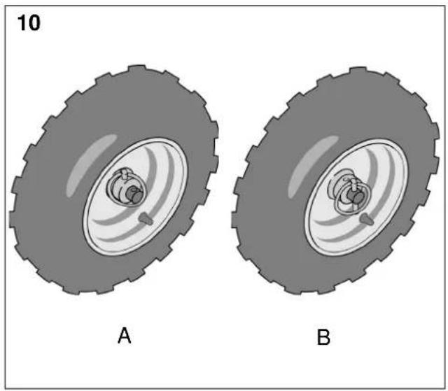
4.18 WHEEL LOCK
See fig. 10. The left wheel is mounted on the wheel shaft with the help of a locking pin. The locking pin can be moved to two positions:
A) Inner position - two-wheel drive.
B) Outer position - one-wheel drive. Simplifies manoeuvring the machine when turning.
- Used during lighter conditions.
- When storing the machine.
4.19 CHUTE DEFLECTOR (A)
Losen the wing nuts and adjust the chute deflector to a suitable height.
Low - shorter ejection distance.
High - longer ejection distance.
4.20 CHUTE CLEARING TOOL (G)
The chute clearing tool is located in a holder on top of the auger housing. The chute clearing tool must always be used when cleaning the discharge chute and augur.
Always stop the engine before clearing the chute.
Never clear the snow discharge chute with your hand. Risk of serious injury.
5 USING THE SNOW THROWER
5.1 GENERAL
Never start the engine until all the above measures under “ASSEMBLY” på sidan 45” have been carried out.

Never use the snow thrower without first reading and understanding the instructions and all the warning and instruction stickers on the machine.

Always use protective goggles or a visor during use, maintenance and service.
5.2 CHECKING THE ENGINE OIL LEVEL (FIG. 11)
Fill the engine with oil before using.

Do not start the engine until filled with oil. The engine can be seriously damaged without oil.
- Place the machine on a level floor.

-
Wipe clean around the oil dipstick. Unscrew and pull it up. Wipe off the dipstick.
-
Slide the dipstick down completely and tighten it.
-
Pull up the dipstick again. Read off the oil level. Top up with oil to the "FULL" mark, if the level comes below this mark.
Use oil SAE 5W30-10W40 in accordance with A.P.I service "SF", "SG" or "SH".
The crankcase holds: 0.6 litres.
- Reinstall the oil filler cap (11:F).
The oil level must never exceed the “FULL” mark. This results in the engine overheating. If the oil level exceeds the “FULL” mark, the oil must be drained until the correct level is achieved.
Always check the oil level before using. The snow thrower must stand on level ground when checking.
5.3 FILL UP THE PETROL TANK
Always use lead-free petrol. Oil-mixed 2-stroke petrol must not be used.
NOTE! Bear in mind that ordinary lead-free petrol is perishable; do not purchase more petrol than can be used within thirty days.
Environmental petrol can be used, i.e. alkylate petrol. This type of petrol has a composition that is less harmful for people and nature.

Petrol is highly inflammable. Always store fuel in containers that are made especially for this purpose.

Store the petrol in a cool, well ventilated place – not in the house. Store the petrol well out of reach for children.

Only fill or top up with petrol outdoors, and never smoke when filling or topping up. Fill with fuel before starting the engine. Never remove the filler cap or fill with petrol while the engine is running or still warm.
Do not fill the petrol tank right to the top. After filling, screw the filler cap on tightly and wipe up any spilt petrol.
5.4 STARTING THE ENGINE (WITHOUT ELECTRICAL START), SEE FIG. 1

Do not touch engine components because they are warm during use and up to 30 minutes after use. Risk of burn injuries.

Never run the machine indoors. The exhaust fumes contain carbon monoxide, a very toxic gas.
- Make sure the driving (N) and auger (O) clutch levers are disengaged.
- Open the fuel cock (M).
- Set the stop switch (S) in position "ON".
- Turn the choke (L) to closed position. Note: A warm engine does not need the choke.
- Press the rubber primer-start (J) 2 or 3 times. Make sure the hole is covered when pressing the primer-start. Note: Do not use this function when the engine is warm.
- Pull on the starter cord (U) until you feel resistance. Start the engine with a sharp pull.
- When the engine starts, reset the choke until it is fully open.
5.5 STARTING THE ENGINE (WITH ELECTRICAL START) (CRYSTAL), SEE FIG. 1

Do not touch engine components because they are warm during use and up to 30 minutes after use. Risk of burn injuries.

Never run the machine indoors. The exhaust fumes contain carbon monoxide, a very toxic gas.
- Attach the connecting cable (T) to an earthed extension lead. Then connect the extension lead to a 220/230 volt earthed socket.
- Make sure the driving (N) and auger (O) clutch levers are disengaged.
-
Open the fuel cock (M).
-
Set the stop switch (S) in position "ON".
- Turn the choke (L) to closed position. Note: A warm engine does not need the choke.
- Press the rubber primer-start (J) 2 or 3 times. Make sure the hole is covered when pressing the primer-start. Note: Do not use this function when the engine is warm.
- Starting the engine: a. Press the start button (R) to activate the starting motor. b. When the engine starts, release the start button and gradually open the choke. c. If the engine stutters, close the choke immediately and gradually open it again. d. First pull out the extension lead from the socket. Then remove the extension lead from the engine.
Note: To prevent damaging the electric starter, run it at intervals of 5 seconds on, then 5 seconds off. If the engine does not start after 10 attempts, allow the starter to cool for at least 40 minutes before trying to start it again. If the engine still does not start, take the engine to an Authorized Service Dealer for service.
- When the engine starts, reset the choke until it is fully open.
5.6 STOPPING
- Release both clutch levers. Note. If the snow thrower continues rotating - see "7.4" below.
- Close the fuel cock (1:M).
- Set the stop switch (1:S) in position "OFF".
5.7 STARTING
- Start the engine as above. Let the engine run a few minutes to warm before use.
- Set the chute deflector.
- Turn the adjustment lever and set the deflector to throw the snow in the direction of the wind.

The gear stick must not be moved if the driving clutch lever is depressed.
- Set the gear lever to a suitable position.
- Press down the auger clutch lever to activate the auger and discharge fan.

Watch out for rotating auger. Keep hands, feet, hair and loose clothing away from any moving parts on the machine.
- Press down the auger clutch lever. The snow thrower now moves forward or backwards depending on the gear you have chosen.
5.8 DRIVING TIPS

The silencer and surrounding parts become very hot when the engine is running. Risk of burns.
- Always run the engine on full throttle or next best.
- Always adapt the speed to the snowy conditions. Regulate the speed with the gear stick.
- Snow is more effectively removed directly after falling.
-
Always throw the snow in the direction of the wind if possible.
-
Adjust the shoes with the screws (1:H) to suit the ground conditions:
- On flat ground, e.g. asphalt, the shoes should be about 3mm under the scraping blade.
- On uneven ground, e.g. gravel paths, the shoes should be about 30mm under the scraping blade.

Always adjust the shoes so that gravel and stones are not fed into the snow thrower. There is a risk for personal injury if these are thrown out at high speed.
Ensure the shoes are adjusted the same on both sides.
- Adapt the speed so that the snow is thrown in an even stream.

If snow fastens in the chute do not try to remove it before:
- Releasing both clutch levers.
- Stopping the engine.
- Disconnecting the cable from the spark plug.
- Do not put your hand inside the chute or auger. Use the chute clearing tool supplied.
5.9 AFTER USE
- Check for loose or damaged parts. If required, change damaged parts.
- Tighten loose screws and nuts.
- Brush all the snow from the machine.
- Move all the controls backwards and forwards a few times.
- Put the choke in closed position.
- Disconnect the starting cable from the spark plug.

Do not cover the machine while the engine and silencer are still warm.
6 MAINTENANCE
6.1 MAINTENANCE SCHEDULE
| Service item Frequency Type | ||
| Motor oil change A | After 2 hours and then every 20:th h | SAE 5W30 - 10W40 |
| Drive belts, check A | After 2 hours and then every year. | |
| Linkages, lubricate | Once per year 10W | oil |
| Tyre pressure, check | 50 hour | |
| Spark plug check/replace | 100 hour | Champ. NHSP LD F7RTC |
6.2 OIL CHANGE
Change the oil the first time after 2 hours of operation, and subsequently every 20 hours of operation or once a season. Change oil when the engine is warm.

The engine oil may be very warm if it is drained off directly after the engine is shut off. So allow the engine to cool a few minutes before draining the oil.
-
Lean the snow thrower slightly so that the oil draining plug (1:Q) is the lowest point of the engine.
-
Unscrew the oil draining plug.
- Let the oil run out into a container.
- Screw back the oil draining plug.
- Fill with new oil: See "checking the engine oil level (FIG. 11)" på sidan 47" above for type and amount.
6.3 SPARK PLUG
Check the spark plug once a year or every hundred hours of use.
Clean or change the plug if the electrodes are burnt. The engine manufacturer recommends: LD F7TC or equivalent.
Correct spark gap: 0.7-0.8 mm.
6.4 CARBURETTOR
The carburettor is factory set. If adjustment is required, contact an authorised service station.
6.5 TYRE PRESSURE
The air pressure should be equal in both tires for best performance. Be sure to keep caps on valves to prevent entry of debris into the valve stem when tires are filled.
Recommended air pressure: 1.2 bar.
6.6 LUBRICATION

No service must be carried out before:
- The engine has stopped.
- The cable has been disconnected from the spark plug.
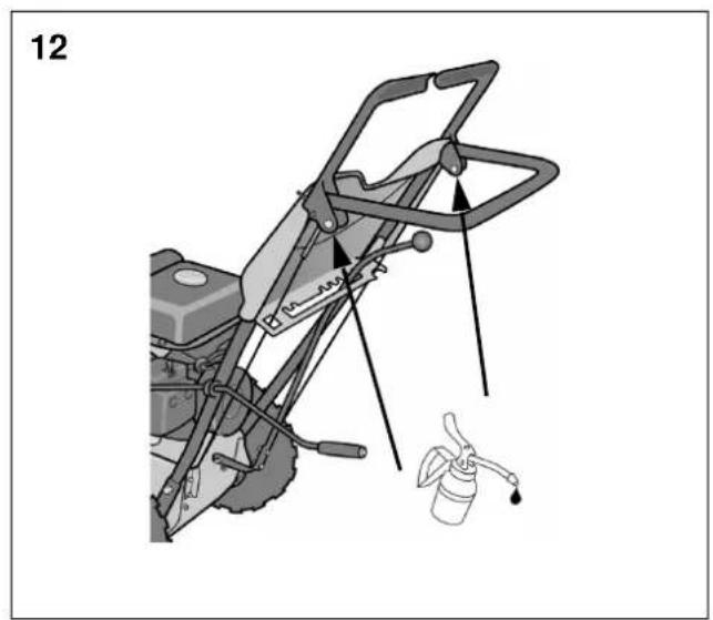
6.6.1 Linkages
See fig. 12. Lubricate the linkages below every 10:th hour of use and before long time storage. Use 10W oil.
- Lever bearings
- Drive belt tension arm
- Auger belt tension arm
6.6.2 Gearbox
No parts inside the gearbox are to be lubricated. All bearings and bushings are permanently lubricated and require no maintenance.
Lubricating these parts will only result in the grease getting on to the friction wheel and disc drive plate, which could damage the rubber clad friction wheel.
For long time storage the above-mentioned parts should be lightly wiped with an oily rag to prevent rust.
7 SERVICE AND REPAIRS

No service must be carried out before:
- The engine has stopped.
- The starting cable has been disconnected from the spark plug.
If the instructions say that the machine is to be lifted at the front and rested on the auger housing then the petrol tank must be emptied.

Empty the petrol tank outdoors when the engine is cold. Do not smoke. Empty into a container designed for petrol.
7.1 TROUBLE SHOOTING
| Problem Possible cause Remedy | ||
| Engine fails to start. | Engine flooded. Rep | cated start attempts with full throttle choke OFF |
| Water in fuel or old fuel. | Drain tank and refill with fresh fuel. | |
| Other. Check carefully the start procedure according to this manual. | ||
| Engine starts hard or runs poorly. | Spark plug faulty. R | replace the spark plug. |
| Fuel cap ventilation is blocked. | Clear the ventilation. | |
| Auger does not rotate. | Foreign matter blocking. | Clean. |
| Shear pin broken. | Replace the broken pin. | |
| Auger drive belt slipping. | Adjust the belt and wire. | |
| Auger drive belt broken. | Replace the belt. | |
| Auger does not stop when the lever is released. | Auger drive belt is out of adjustment. | Adjust the belt. |
| Auger drive guide is out of adjustment. | Adjust the guide. | |
| Snowthrower veers to one side. | Tire pressure not equal. | Adjust the tire pressure |
| Only one wheel drives. | Check the wheel locks. | |
| Shoes uneven adjusted. | Adjust scraper blade and shoes. | |
| Scraper blade uneven adjusted. | Adjust scraper blade and shoes. | |
7.2 ADJUSTING THE SCRAPER BLADE AND SHOES
The scraper blade (1:V) and shoes (1:H) gets worn after a long term of use.
Adjust the scraper blade (always together with the shoes) until desired distance to the ground.
The scraper blade and the shoes are reversible and can be used on both sides.
See "STARTING" på sidan 48".
7.3 GENERAL ABOUT DRIVE BELTS
The drive belts should be checked and adjusted once per season and replaced when needed. This should all be done at an authorised service station.
7.4 ADJUSTING THE CONTROL WIRES
When the belts are replaced, the control wires must also be adjusted (see below).
7.4.1 Wire - auger
- Disconnect the ignition cable from the spark plug.
-
Press down the lever (1:O). The lever should provide some resistance when pressed, and spring back in place when let go.
-
Adjust as described below:
Untighten the locking nut
Screw the adjustment rod into desired position with use of the fingers.
Secure the adjustment rod by tightening the locking nut. -
Recheck the adjustment according to position 2 above and, if nessecary, make new adjustments.
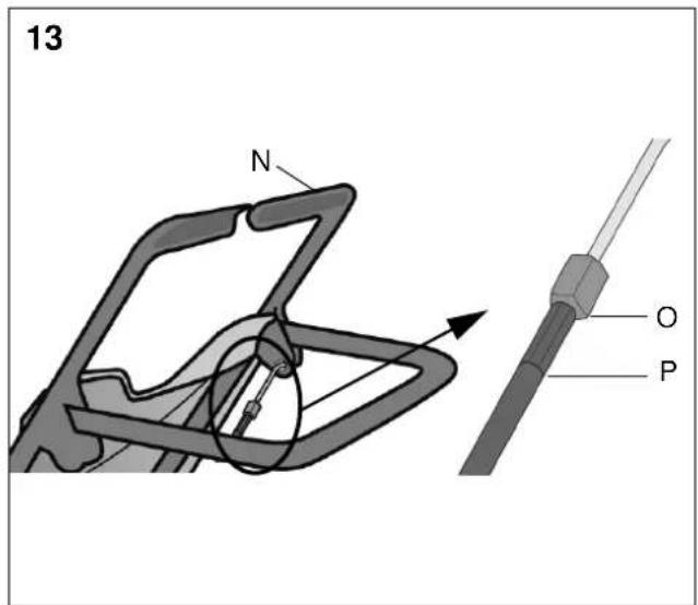
7.4.2 Wire - drive
- With the engine running and a gear chosen, check the drive as described below:
- If the machinedo not drive when the drive lever (13:N) is pressed down/activated, the wire has to be tensed
-
If the machine drive even when the drive lever (13:N) is released/not activated the tension in the wire has to bereduced.
-
Stop the engine.
-
Adjust as described below:
- Untighten the locking nut (13:O)
- Screw the adjustment rod (13:P) into desired position with use of the fingers.
Note! a wire that is too tense increases the wear, therefore tensioning should be performed a little bit at the time
- Secure the adjustment rod by tightening the locking nut.
- Recheck the adjustment according to position 1 above and, if nessecary, make new adjustments.
7.5 REPLACING THE SHEAR BOLTS (1:W)
The auger is fastened to the shaft by special bolts that are designed to break if something gets stuck in the auger housing.

Always use genuine spare parts. Other types of bolts could cause serious damage to the machine.
- Stop the engine.
- Disconnect the ignition cable from the spark plug.
- Ensure all the rotating parts have stopped.
- Remove the object that has fastened in the auger.
- Align the holes in the shaft and auger.
- Remove the broken bolt parts.
- Assemble a new original shear bolt.
8 STORAGE

Never store the snow thrower with petrol in the tank in a confined area with bad ventilation. Petrol fumes could reach open flames, sparks, cigarettes etc.
If the snow thrower is to be stored for a longer period than 30 days, the following measures are recommended:
- Empty the petrol tank.
- Start the engine and let it run until it stops due to lack of fuel.
- Change the engine oil if it has not been done for 3 months.
- Remove the spark plug and empty a little engine oil (about 30ml) in the hole. Crank the engine a couple of times. Screw back the spark plug.
- Clean the whole snow thrower thoroughly.
- Lubricate all the parts as shown in "LUBRICATION" på sidan 49" above.
- Inspect the snow thrower for damage. Repair if necessary.
- Touch up any paint damage.
- Rust protect the metal surfaces.
- Store the snow thrower indoors if possible.
9 IF SOMETHING BREAKS
Authorised service workshops carry out repairs and guarantee service. Always use genuine spare parts.
Do you carry out simple repairs yourself? Always use genuine spare parts. They fit perfectly and make the work much easier.
Spare parts are available at your retailer and service station.
When ordering spare parts: Specify the model, year of purchase, the engine model and type number.
10 PURCHASE TERMS
A full warranty is issued against manufacturing and material defects. The user must carefully follow the instructions given in the enclosed documentation.
Exceptions:
The warranty does not cover damage due to:
- Neglect by the user to acquaint themselves with accompanying documentation
- Carelessness
- Incorrect and non-permitted use or assembly
- The use of non-genuine spare parts
- The use of accessories not supplied or approved by GGP
Neither does the guarantee cover: - Wear parts such as drive belts, augers, headlights, wheels, shear bolts and wires
- Normal wear
- Engines. These are covered by the engine manufacturer's warranties, with separate terms and conditions.
The purchaser is covered the national laws of each by each country. The rights to which the purchaser is entitled with the support of these laws are not restricted by this warranty.
1 GÉNÉRALITÉS

4.8 POIGNÉE DE DÉMARREUR (U)
4.8 UCHWYT ROZRUCHOWY (U)
Zalecane ciśnienie to: 1,2 bar.
6.5 GAŹNIK
4.3 PŘÍMÝ VSTŘIK PALIVA (J)

4.17 PATKY NABÍRACÍHO ÚSTROJÍ (H)
10 SMLUVNÍ PODMÍNKY PRODEJE
7.5 A NYÍRÓCSAVAROK CSERÉJE (1:W)
4.14 ROČICA SKLOPKE – VOŽNJA (N)

4.6 ŠTARTOVACIA RUKOVÄT (U)
5.3 NAPLŇTE NÁDRŽ NA BENZÍN
4.14 SIDURIKANG - JUHTIMINE (N)

4.14 PAVAROS SANKABOS SVIRTIS (N)

4.2 GAISA VÄRSTS (L)
ST 3256 P, ST 3262 P