Snow Blizzard - Snow blower STIGA - Free user manual and instructions
Find the device manual for free Snow Blizzard STIGA in PDF.

| Product Type | Snow thrower |
| Brand | Stiga |
| Model | Snow Blizzard |
| Power Source | Unleaded gasoline |
| Engine Type | 4-stroke |
| Engine Oil Capacity | 0.8 liter (SAE 5W30 or 10W30) |
| Transmission | 6 forward speeds, 2 reverse speeds |
| Starting | Manual (recoil) and electric (220/230 V) |
| Tire Pressure | 1.0 - 1.2 bar |
| Spark Plug | Champion RC12YC (gap 0.7-0.8 mm) |
| Headlight Bulb | 27 W |
| Safety | Ignition key, automatic shutdown, anti-throw protection |
| Approximate dimensions (L x W x H) | 140 x 60 x 100 cm |
| Approximate weight | 85 kg |
| Included Accessories | Cleaning tool, replacement shear bolts |
| Maintenance | Oil change every 50 hours, belt inspection, regular lubrication |
| Warranty | Full warranty on material and manufacturing defects (excluding wear parts) |
Frequently Asked Questions - Snow Blizzard STIGA
User questions about Snow Blizzard STIGA
0 question about this device. Answer the ones you know or ask your own.
Ask a new question about this device
Download the instructions for your Snow blower in PDF format for free! Find your manual Snow Blizzard - STIGA and take your electronic device back in hand. On this page are published all the documents necessary for the use of your device. Snow Blizzard by STIGA.
USER MANUAL Snow Blizzard STIGA
natural_image
Illustration of a snowman with visible blades and handle (no text or symbols)BRUKSANVISNING SV ....5
KÄYTTÖOHJEET FI ...12
BRUGSANVISNING DA... 19
BRUKSANVISNING NO .. 26
KASUTUSJUHISED ET.119
NAUDOJIMO INSTRUKCIJOS LT.126
LIETOŠANAS INSTRUKCIJA LV.134
STIGA
CONSUMER
SNOW BLIZZARD
natural_image
Technical line drawing of a mechanical assembly with a flange and housing, showing no text or symbols
natural_image
Illustration of a snowman with visible blades and handle (no text or symbols)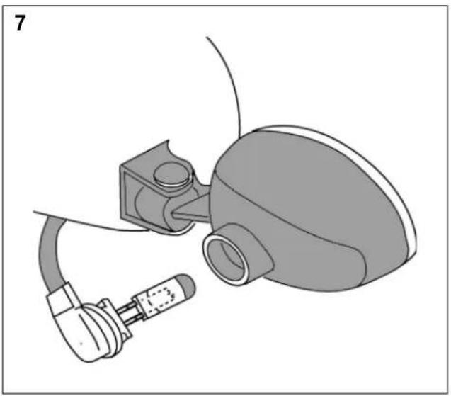
natural_image
Medical device diagram showing a connector and internal components (no text or labels)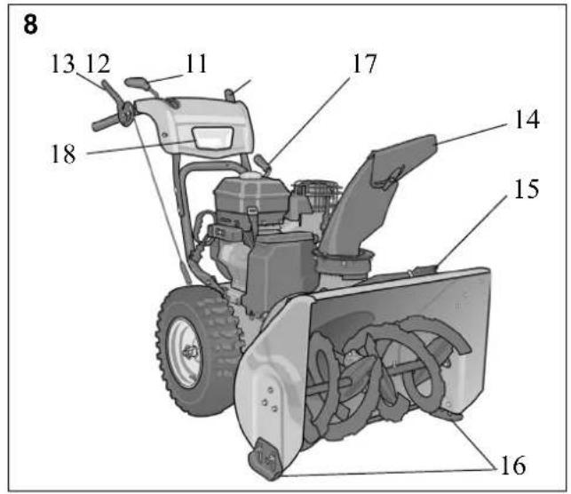
natural_image
Mechanical assembly diagram showing a clamping mechanism with no visible text or symbols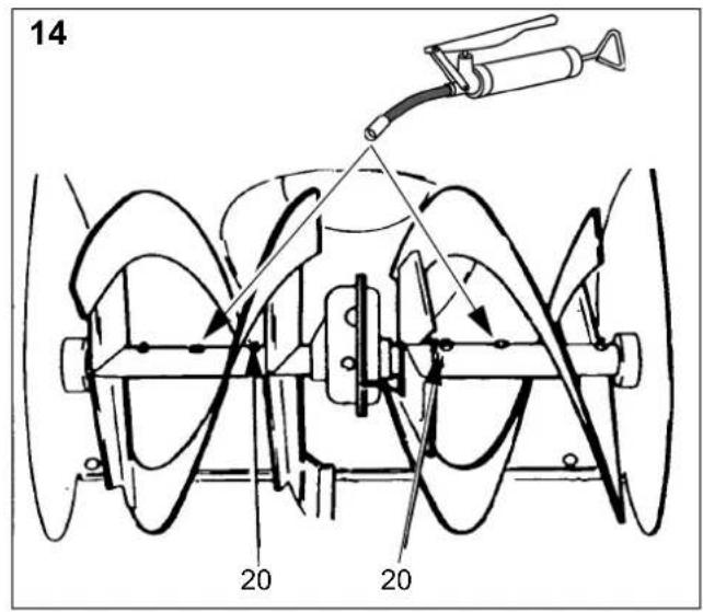
1 SYMBOLER
4.14 RIKTSKÄRM - UTKAST (14)
Advarsel.
4.18 RENSEVÆRKT∅J (15, FIG. 8)
2.4 VEDLIKEHOLD OG OPPBEVARING
4.3 TENNINGSN∅KKEL (4)
4.18 RENSEVERKT∅Y (15, FIG. 8)
6.1 VEDLIKEHOLDSPLAN
The following symbols appear on the machine. They are there to remind you of the care and attention required in use.
This is what the symbols mean:
Warning.
Read the owner's manual before operating the machine.
Danger - rotating auger. Keep hands out of discharge chute.
Danger - rotating fan.
Keep hands and feet away from rotating parts.
Keep bystanders at a safe distance from the machine.
Never point the discharge chute towards bystanders.
Before starting work on the machine, remove the ignition key from the machine.
Risk of burns.
Use hearing protection.
Risk of toxic vapours.
Risk of fire.
2 SAFETY INSTRUCTIONS
2.1 GENERAL
- Please read through these instructions carefully. Learn all the controls and the correct use of the machine.
- Never allow children or anyone who is not familiar with these instructions to use the snow thrower. Local regulations may impose restrictions as regards the age of the driver.
- Never use the machine if others, particularly children or animals, are in the vicinity.
- Remember that the driver is responsible for accidents that happen to other people or their property.
- Be careful not to trip or fall, especially when reversing the machine.
- Never use the snow thrower under the influence of alcohol or medication and if you are tired or ill.
2.2 PREPARATIONS
- Check the area to be cleared and remove any loose or foreign objects.
- Disengage all controls before starting the engine.
-
Never use the snow thrower unless properly dressed. Wear footwear that improves your grip on a slippery surface.
-
Warning – Petrol is highly inflammable.
a. Always store petrol in containers that are made especially for this purpose.
b. Only fill or top up with petrol outdoors, and never smoke when filling or topping up.
c. Fill with petrol before starting the engine. Never remove the filler cap or fill with petrol while the engine is running or still warm.
d. Screw the filler cap on tightly and wipe up any spilt petrol. - Adjust the height of the auger housing to ensure it stays above gravel paths.
- Never, under any circumstances, make adjustments while the engine is running (unless otherwise specified in the instructions).
- Allow the snow thrower to adjust to the outdoor temperature before using it.
- Always use protective goggles or a visor during use, maintenance and service.
2.3 OPERATION
- Keep hands and feet away from rotating parts. Always avoid the discharge chute opening.
- The snow thrower must never be used to remove anything but snow
- Be careful when driving on or crossing gravel paths, pavements and roads. Be aware of hidden dangers and traffic.
- Never direct the discharge chute towards a public road or traffic.
- If the snow thrower hits a foreign object, stop the engine, disconnect the spark plug cable and carefully inspect the machine for damage. Repair the damage before using the machine again.
- If the machine starts vibrating abnormally, stop the engine and look for the cause. Vibration is normally a sign of something wrong.
- Stop the engine and disconnect the spark plug cable: a. If the machine steers away from the driving position. b. If the auger housing or discharge chute is blocked and must be cleaned. c. Before beginning repairs or adjustments.
• Always make sure the rotating parts have stopped and all the controls are disengaged before cleaning, repairing or inspection.
- Before leaving the machine unattended, disengage all the controls, put it into neutral gear, stop the engine and remove the ignition key.
- Never run the engine indoors except when taking it in and out of its place of storage. In this case ensure the door to the storage place is open. Exhaust fumes are toxic.
- Never drive across a slope. Move from the top down, and from the bottom to the top. Be careful when changing direction on a slope. Avoid steep slopes.
- Never operate the machine with insufficient protection or without the safety devices in place.
- Existing safety devices must not be disconnected or disengaged.
- Do not alter the engine's regulator setting and do not race the engine. The possibility of personal injury increases when the engine is run at high revs.
- Never use the snow thrower near enclosures, cars, windowpanes, slopes etc. without properly setting the discharge chute deflector.
• Always keep children away from areas to be cleared. Get another adult to keep the children under supervision. - Do not overload the machine by driving it too fast.
• Take care when reversing. Look behind you before and during reversing to check for any obstacles. - Never point the discharge chute towards bystanders. Do not allow anyone to stand in front of the machine.
- Disengage the auger when the snow thrower is to be transported or is not in use Do not drive too fast on slippery surfaces when transporting.
- Only use accessories that are approved by the machine's manufacturer.
- Never drive the snow thrower in bad visibility or without satisfactory lighting.
• Always ensure you have a good balance and a tight grip on the handle. - Do not touch engine components because they are warm during use. Risk of burn injuries.
2.4 MAINTENANCE AND STORAGE
- Tighten all nuts and screws so that the machine is in safe working condition. Check the shear bolts regularly.
- Always use genuine spare parts. Non-genuine spare parts can entail a risk of injury, even if they fit the machine.
- Never store the machine with petrol in the tank in buildings where the fumes can come into contact with open flames or sparks.
- Allow the engine to cool before putting the machine in store.
- Before a long storage, check the instructions for recommendations.
- Replace damaged warning and instruction stickers.
- Let the engine run a couple of minutes with the auger connected after use. This prevents the auger from freezing solid.
3 ASSEMBLY
Note: Instructions to the left and right sides start from the driving position behind the snow thrower.
3.1 CONTENTS - OUTER PACKING
The packing contains:
- One snow thrower
- One adjustment lever
- Gear lever
- One discharge chute
- One set of instructions
- One assembly kit
In addition, the following are supplied:
- Chute clearing tool (15 in fig. 8)
- Extra break bolts for spare
3.2 UNPACKING
- Remove all loose items from the carton.
-
Cut the four corners of the carton and let the sides fall down.
-
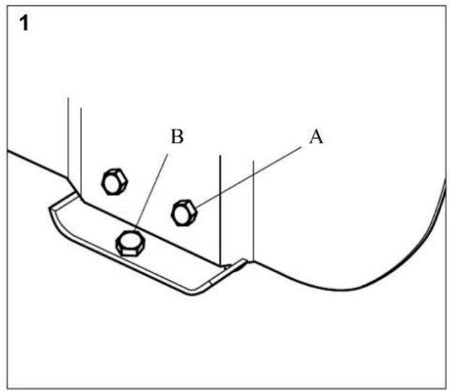
Unscrew the screws (B) that fasten the shoes to the bedding. See fig. 1. (some models only)
- Roll the snow thrower from the carton.
- Cut the plastic tape holding the control wires on the underside of the handle.
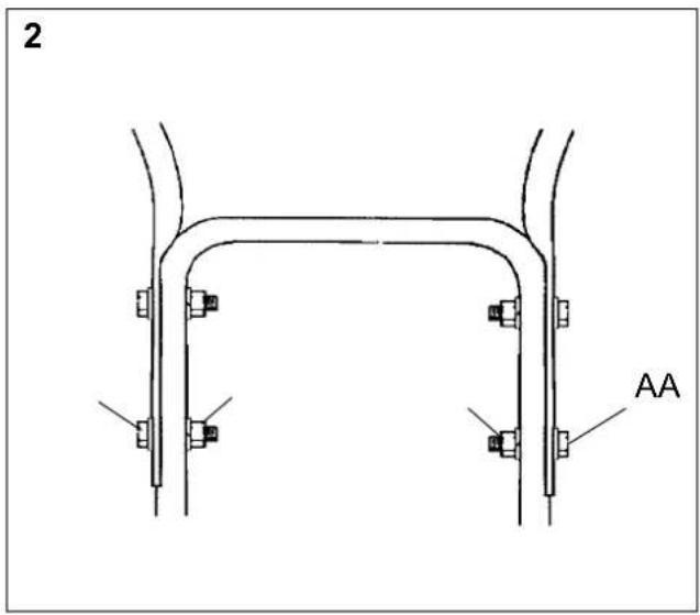
3.3 HANDLE, FIG. 2
- Loosen, but do not remove, the securing nuts in the upper holes.
- Fold up the upper part of the handle. NOTE! Make sure the control wires do not jam.
- Fit screws from the outside in the lower holes and assemble with the following parts:
A Screws D Lock nut - Tighten the four nuts.
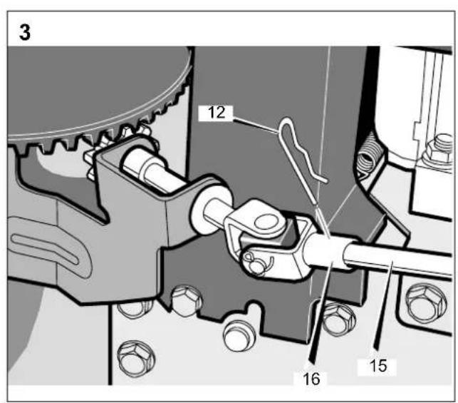
3.4 ADJUSTMENT LEVER, SEE FIG. 3
- Remove the locking pin (12).
- Place the shaft (15) in the sleeve (16) in the toggle joint.
- Lock the joint with the locking pin (12).
- Check the discharge chute by turning it fully in both directions. The chute should rotate freely.
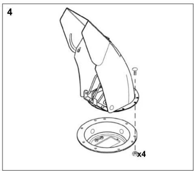
3.5 SNOW DISCHARGE CHUTE, SEE FIG. 4
- Turn the adjustment lever anti-clockwise until it resists.
- Place the discharge chute (2) facing 90^ degrees left on the flange so the holes meet.
- Mount the four nuts and bolts.
- Tighten properly.
- Check the discharge chute by turning it fully in both directions. The chute should rotate freely.
3.6 CHECKING THE CONTROL WIRES
The control wires might need adjusting before using the snow thrower for the first time.
See ADJUSTING THE CONTROL WIRES below.
3.7 TYRE PRESSURE
Check the air pressure in the tyres. Correct air pressure: 1.0 - 1.2 bar.
4 CONTROLS
See figures 8-11.
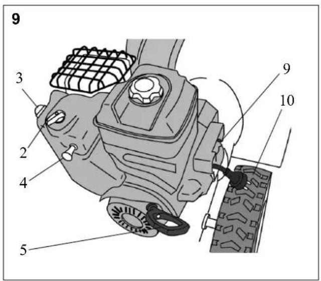
4.1 CHOKE (2)
Used when starting a cold engine:

-
The choke is open
-
The choke is closed (for cold starting)
4.2 PRIMER (3)

Pressing the rubber prime-starter squirts fuel into the carburettor intake pipe to make it easier to start a cold engine.
4.3 IGNITION KEY (4)
Must be fully inserted or the engine will not start. Do not turn the key!

- Key fully inserted – engine can start.
- Key pulled out - engine cannot start.
4.4 STARTING HANDLE (5)
Manual cord start with rewinding
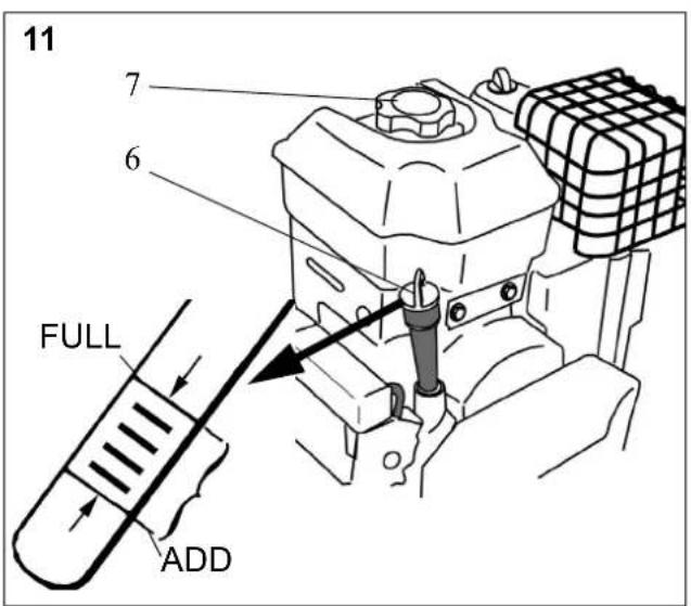
4.5 DIPSTICK (6)

For filling and checking the oil level in the engine.
The dipstick has two level marks:
FULL = maximum oil level
ADD = minimum oil level
4.6 FILLER CAP (7)

a. For filling with petrol.
4.7 OIL DRAINING PLUG (8)
For draining the old engine oil when changing the oil.
4.8 START BUTTON - ELECTRICAL START (9)
Activates the electric starting motor.
4.9 ELECTRIC CABLE - ELECTRICAL START (10)
Supplies power to the starting motor. Connect the cable to a 220/230 volt earthed socket via an earthed extension lead. It is wise to use an earth fault breaker.
4.10 GEAR LEVER (11)
The machine has 6 forward gears and 2 reverse to regulate the speed.
The gear stick must not be moved if the driving clutch lever is depressed.
4.11 CLUTCH LEVER- DRIVING (12)
Engages the wheels when put into gear and the lever is pushed towards the handle.
Situated on the left side of the handle.
4.12 CLUTCH LEVER- AUGER (13)
Connects the auger and fan when the lever is pushed down towards the handle.
Situated on the right side of the handle.
4.13 ONE HAND CONTROL
The machine is equipped with one hand control, which means that the clutch lever driving can lock the clutch lever auger in activated position. Perform as follows:
- Start the engine.
- Press the clutch lever auger and the clutch lever driving.
- Remove the hand from the clutch lever auger and it will still be activated.
4.14 CHUTE DEFLECTOR (14)
Loosen the wing nut and set the height of the deflector (fig 9).
Lowered - shorter throwing distance.
Raised - longer throwing distance.
4.15 ADJUSTMENT LEVER (17)
Changes the direction of the discharged snow.

- Turn the lever clockwise - the discharge turns to the right.

- Turn the lever anti-clockwise - the discharge turns to the left.
4.16 SHOES (16)
Used to set the height of the auger housing above the ground.
4.17 HEADLAMP (18)
The headlamp is always activated when the motor is running.
4.18 CHUTE CLEARING TOOL (15)
The chute clearing tool is located in a holder on top of the auger housing. The chute clearing tool must always be used when cleaning the discharge chute and auger.
Always stop the engine before clearing the chute.
Never clear the snow discharge chute with your hand. Risk of serious injury.
Use the chute clearing tool supplied.

5 USING THE SNOW THROWER
5.1 GENERAL
Never start the engine until all the above measures under ASSEMBLY have been carried out.

Never use the snow thrower without first reading and understanding the instructions and all the warning and instruction stickers on the machine.

Always use protective goggles or a visor during use, maintenance and service.
5.2 BEFORE STARTING
Check the engine oil before using.

Do not start the engine until filled with oil. The engine can be seriously damaged without oil.
- Place the machine on a level floor.
- Loosen the dipstick (6) and read the oil level. See fig. 11.
- The oil level shall be between the marks "ADD" and "FULL".
- If necessary fill with oil up to the FULL mark. See fig. 11.
- Use good quality oil marked A.P.I service SF, SG or SH. Use SAE 5W30 oil. Use SAE 10W30 oil for temperatures under -18°C.
Do not use SAE 10W40.
5.3 FILL UP THE PETROL TANK
Always use lead-free petrol. Oil-mixed 2-stroke petrol must not be used.
NOTE! Bear in mind that ordinary lead-free petrol is perishable; do not purchase more petrol than can be used within thirty days.
Environmental petrol can be used, i.e. alkylate petrol. This type of petrol has a composition that is less harmful for people and nature.

Petrol is highly inflammable. Always store fuel in containers that are made especially for this purpose.

Store the petrol in a cool, well ventilated place – not in the house. Store the petrol well out of reach for children.

Only fill or top up with petrol outdoors, and never smoke when filling or topping up. Fill with fuel before starting the engine. Never remove the filler cap or fill with petrol while the engine is running or still warm.
Do not fill the petrol tank right to the top. After filling, screw the filler cap on tightly and wipe up any spilt petrol.
5.4 STARTING THE ENGINE (WITHOUT ELECTRICAL START)
- Make sure the driving and auger clutch levers are disengaged. See 12, 13 in fig. 8
- Put in the ignition key. Ensure it clicks tight. Do not turn the key!
- Turn the choke to position . Note: A warm engine does not need the choke.
- Press the rubber primer-start (3 in fig. 9) 2 or 3 times. Make sure the hole is covered when pressing the primer-start. Note: Do not use this function when the engine is warm.
- Pull on the starter cord until you feel resistance. Start the engine with a sharp pull.
- When the engine starts, turn the choke anti-clockwise until it is fully open.

Never run the machine indoors. The exhaust fumes contain carbon monoxide, a very toxic gas.
5.5 STARTING THE ENGINE (WITH ELECTRICAL START)
- Attach the connecting cable to an earthed extension lead. Then connect the extension lead to a 220/230 volt earthed socket.
- Make sure the driving and auger clutch levers are disengaged. See 12, 13 in fig. 8.
-
Put in the ignition key. Ensure it clicks tight. Do not turn the key!
-
Turn the choke to position . Note: A warm engine does not need the choke.
-
Press the rubber primer-start (3 in fig. 9) 2 or 3 times. Make sure the hole is covered when pressing the primer-start. Note: Do not use this function when the engine is warm.
-
Starting the engine: a. Press the start button to activate the starting motor.
b. When the engine starts, release the start button and open the choke by slowly turning the choke lever anticlockwise to position |N|
c. If the engine stutters, close the choke immediately and gradually open it again.
d. First pull out the extension lead from the socket. Then remove the extension lead from the engine.
Note: The electrical starting motor has overload protection. The motor stops automatically when overheated. It will not restart until it has cooled, which takes about 5 - 10 minutes.
- When the engine starts, turn the choke anti-clockwise until it is fully open.

Never run the machine indoors. The exhaust fumes contain carbon monoxide, a very toxic gas.
5.6 SAFETY TEST
This machine is equipped with several mechanical safety systems, designed to keep the operator safe while using the unit.
After starting and before use of the machine, it is essential to perform the safety test below.
If the unit fails to operate as described, DO NOT operate it. In this case, contact an authorised workshop for repair.
Auger test
- The engine shall be running.
- Press down the auger lever and the auger shall rotate.
- Release the auger lever and the auger shall stop within 5 seconds.
Drive test
- The engine shall be running and the gear lever in 1st gear alt. the speed lever in low speed.
- Press down the driving lever and the unit shall move.
- Release the driving lever and the unit shall stop.
5.7 STOPPING
- Release both clutch levers. Note. If the snow thrower continues rotating - see ADJUSTING THE CONTROL WIRES below.
- Remove the ignition key. Do not turn the key!

If the machine is left unattended, stop the engine and remove the ignition key.
5.8 STARTING
- Start the engine as above. Let the engine run a few minutes to warm before use.
- Set the chute deflector.
- Turn the adjustment lever and set the deflector to throw the snow in the direction of the wind.
- Set the gear lever to a suitable position.

The gear stick must not be moved if the driving clutch lever is depressed.
- Press down the auger clutch lever (13 in fig. 8) to activate the auger and discharge fan.

Watch out for rotating auger. Keep hands, feet, hair and loose clothing away from any moving parts on the machine.
- Press down the auger clutch lever (12 in fig. 8). The snow thrower now moves forward or backwards depending on the gear you have chosen.
5.9 DRIVING TIPS

The silencer and surrounding parts become very hot when the engine is running. Risk of burns.
-
Always adapt the speed to the snowy conditions. Regulate the speed with the gear stick not the throttle.
-
Snow is more effectively removed directly after falling.
-
Always throw the snow in the direction of the wind if possible.
-
Adjust the shoes with the screws (A in fig. 1) to suit the ground conditions:
- On flat ground, e.g. asphalt, the shoes should be about 3 mm under the scraping blade.
- On uneven ground, e.g. gravel paths, the shoes should be about 30 mm under the scraping blade.

Always adjust the shoes so that gravel and stones are not fed into the snow thrower. There is a risk for personal injury if these are thrown out at high speed.
Ensure the shoes are adjusted the same on both sides.
- Adapt the speed so that the snow is thrown in an even stream.

If snow fastens in the chute do not try to remove it before:
- Releasing both clutch levers. Stopping the engine.
- Removing the ignition key.
- Do not put your hand inside the chute or auger.
Use the chute clearing tool supplied.
5.10 AFTER USE
-
Check for loose or damaged parts. If required, change damaged parts.
-
Tighten loose screws and nuts.
-
Brush all the snow from the machine.
-
Move all the controls backwards and forwards a few times.
-
Put the choke in position |-|

Do not cover the machine while the engine and silencer are still warm.
6 MAINTENANCE
6.1 MAINTENANCE SCHEDULE
| Service item Frequency Par. | |||
| Safety test Before every start | 5.6 | ||
| Motor oil change After 2 hour and then every 50:th hour. | SAE 5W30 - 10W40 | 6.2 | |
| Drive belts, check After 2 hour and then every year. | 8.2 | ||
| Auger shaft, lubricate | 10 hour Lithium grease | 7.2 | |
| Mechanism for chute rotation, lubricate/check | 10 hour 10W oil | - | |
| Deflector, lubricate | 10 hour 10W oil | - | |
| Wires, lubricate | 10 hour 10W oil | - | |
| Linkages, lubricate | 10 hour 10W oil | - | |
| Tyre pressure, check | 50 hour | 3.7 | |
| Auger worm gear, check | 50 hour Winter weight worm gear oil | - | |
| Spark plug check/replace | 100 hour | RC124YC | 6.3 |
6.2 OIL CHANGE
Change the oil the first time after 2 hours of operation, and subsequently every 25 hours of operation or once a season. Change oil when the engine is warm.

The engine oil may be very warm if it is drained off directly after the engine is shut off. So allow the engine to cool a few minutes before draining the oil.
-
Lean the snow thrower slightly to the right so that the oil draining plug is the lowest point of the engine.
-
Unscrew the oil draining plug.
-
Let the oil run out into a container.
-
Screw back the oil draining plug.
-
Fill with new oil: See BEFORE STARTING above for type.
Oil amount in the crankcase: 0.8 litre
6.3 SPARK PLUG
Check the spark plug once a year or every hundred hours of use.
Clean or change the plug if the electrodes are burnt. The engine manufacturer recommends: Champion RC12YC.
Correct spark gap: 0.7/-0.8 mm
6.4 CARBURETTOR
The carburettor is factory set. If adjustment is required, contact an authorised service station.
7 LUBRICATION

No service must be carried out before: The engine has stopped.
The ignition key has been removed.
- The starting cable has been disconnected from the spark plug.
If the instructions say that the machine is to be lifted at the front and rested on the auger housing then the petrol tank must be emptied.

Empty the petrol tank outdoors when the engine is cold. Do not smoke. Empty into a container designed for petrol.
7.1 DISCHARGER
Lubricate the discharger flange and the adjustment lever worm gear every 5th hour of use and before long time storage.
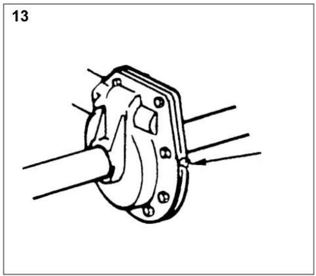
7.2 THE AUGER SHAFT
Lubricate the auger shaft lubricating nipples with a grease gun every 10th hour of use (fig 13). Always lubricate the shaft when changing the shear bolts.
Dismantle the bolts for long time storage. Lubricate with the grease gun and then rotate the auger freely on the shaft before replacing the bolts.
7.3 WORM GEAR
The worm gear is filled with special lubricant at the factory. Refilling is not normally required.
Loosen the plug once a year and check if the worm gear contains lubricant (fig 13).
If it is leaking or has been repaired it must be refilled with lubricant. The worm gear holds 92 grams of lubricant at the most.
Use Shell Darina 1, Texaco Thermatex EP1, Mobiltem 78, Benalene #372 Grease or similar.
8 SERVICE AND REPAIRS

No service must be carried out before: The engine has stopped.
The ignition key has been removed.
If the instructions say that the machine is to be lifted at the front and rested on the auger housing then the petrol tank must be emptied.

Empty the petrol tank outdoors when the engine is cold. Do not smoke. Empty into a container designed for petrol.
8.1 ADJUSTING THE SCRAPER BLADE
The scraper blade gets worn after a lot of use.
Adjust the scraper blade (always together with the shoes)
The scraper blade is reversible so can be used on both sides.
8.2 GENERAL ABOUT DRIVE BELTS
The drive belts should be checked and adjusted once per season and replaced when needed. This should all be done at an authorised service station.
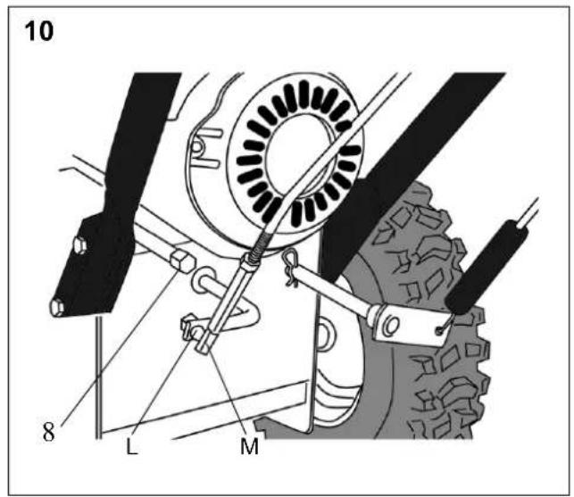
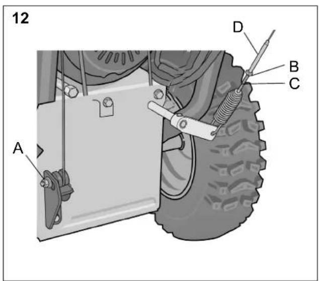
8.3 ADJUSTING THE DRIVING WIRE
See fig 12.
- Loosen the nut (A).
- Pull the wheel unit backwards by hand until the slackness disappear.
- Tighten the nut (A).
8.4 ADJUSTING THE AUGER WIRE
See fig 12.
- Loosen the nut (B).
- Screw the threaded part (C) into the sleeve (D) until the slackness disappear.
- Tighten the nut (B).
8.5 REPLACING THE SHEAR BOLTS
The auger is fastened to the shaft by special bolts (20 in fig. 14) that are designed to break if something gets stuck in the auger housing.

Always use genuine spare parts. Other types of bolts could cause serious damage to the machine. 1. Stop the engine.
-
- Disconnect the starting cable from the spark plug.
- Ensure all the rotating parts have stopped.
- Remove the object that has fastened in the auger.
- Lubricate the auger shaft (see above).
- Align the holes in the shaft and the auger.
- Remove the defective bolt parts.
- Assemble the new genuine bolt. If the bolt unit also include a distance washer, this shall be placed into the bigger hole in the auger shaft.
8.6 HEADLAMP BULB

Only 27 W original spare part bulb is allowed to be used. Bulbs with higher power will damage the headlamp.
The headlamp bulb is fitted to the headlamp by a bayonet socket. See fig. 7. To replace the bulb proceed as follows:
- Turn the bulb about 45^ CCW and pull it out.
- Release the plastic locks at each side of the bulb and pull off the cable connection from the bulb.
- Fit the new bulb in the reverse order.
9 STORAGE

Never store the snow thrower with petrol in the tank in a confined area with bad ventilation. Petrol fumes could reach open flames, sparks, cigarettes etc.
If the snow thrower is to be stored for a longer period than 30 days, the following measures are recommended:
- Empty the petrol tank.
- Start the engine and let it run until it stops due to lack of fuel.

Empty the petrol tank outdoors when the engine is cold. Do not smoke. Empty into a container designed for petrol.
- Change the engine oil if it has not been done for 3 months.
- Remove the spark plug and empty a little engine oil (about 30ml) in the hole. Crank the engine a couple of times. Screw back the spark plug.
- Clean the whole snow thrower thoroughly.
- Lubricate all the parts as shown in LUBRICATING above.
- Inspect the snow thrower for damage. Repair if necessary.
- Touch up any paint damage.
- Rust protect the metal surfaces.
- Store the snow thrower indoors if possible.
10 IF SOMETHING BREAKS
Authorised service workshops carry out repairs and guarantee service. Always use genuine spare parts.
Do you carry out simple repairs yourself? Always use genuine spare parts. They fit perfectly and make the work much easier.
Spare parts are available at your retailer and service station.
When ordering spare parts: Specify the model, year of purchase, the engine model and type number.
11 PURCHASE TERMS
A full warranty is issued against manufacturing and material defects. The user must carefully follow the instructions given in the enclosed documentation.
Warranty period
For consumer use: One year from date of purchase.
For commercial use: Three months from the date of purchase.
Exceptions
The warranty does not cover damage due to:
- Neglect by the user to acquaint themselves with accompanying documentation
- Carelessness
- Incorrect and non-permitted use or assembly
- The use of non-genuine spare parts
- The use of accessories not supplied or approved by Stiga Neither does the guarantee cover:
- Wear parts such as drive belts, augers, headlights, wheels, shear bolts and wires
- Normal wear
- Engines. These are covered by the engine manufacturer's warranties, with separate terms and conditions.
The purchaser is covered the national laws of each by each country. The rights to which the purchaser is entitled with the support of these laws are not restricted by this warranty.
1 SYMBOLLEN
Waarschuwing.
3.3 HANDGREEP, FIG. 2
De motor is gestopt.
De motor is gestopt.
Attention.
3.3 GUIDON, VOIR FIG. 2
¡Advertencia!
Avvertenza.
4.3 CHIAVE DI ACCENSIONE (4)
11 SMLUVNÍ PODMÍNKY PRODEJE
Opozorilo.
5.3 NAPLŇTE NÁDRŽ NA BENZÍN
The headlamp is always activated when the motor is running.
4.18 RENNI PUHASTUSSEADE (15)
The headlamp is always activated when the motor is running.