X502 Ultra Carbon Puro - Motorcycle helmet Nolan - Free user manual and instructions
Find the device manual for free X502 Ultra Carbon Puro Nolan in PDF.
User questions about X502 Ultra Carbon Puro Nolan
0 question about this device. Answer the ones you know or ask your own.
Ask a new question about this device
Download the instructions for your Motorcycle helmet in PDF format for free! Find your manual X502 Ultra Carbon Puro - Nolan and take your electronic device back in hand. On this page are published all the documents necessary for the use of your device. X502 Ultra Carbon Puro by Nolan.
USER MANUAL X502 Ultra Carbon Puro Nolan
SAFETY AND INSTRUCTIONS FOR USE
natural_image
Side profile of a white and black X-lite motorcycle helmet (no text or symbols visible)
bar
| Category | Value | |---|---| | Category 1 | 100 | | Category 2 | 100 | | Category 3 | 100 | | Category 4 | 100 | | Category 5 | 100 | | Category 6 | 100 | | Category 7 | 100 | | Category 8 | 100 | | Category 9 | 100 | | Category 10 | 100 | | Category 11 | 100 | | Category 12 | 100 | | Category 13 | 100 | | Category 14 | 100 | | Category 15 | 100 | | Category 16 | 100 | | Category 17 | 100 | | Category 18 | 100 | | Category 19 | 100 | | Category 20 | 100 | | Category 21 | 100 | | Category 22 | 100 | | Category 23 | 100 | | Category 24 | 100 | | Category 25 | 100 | | Category 26 | 100 | | Category 27 | 100 | | Category 28 | 100 | | Category 29 | 100 | | Category 30 | 100 | | Category 31 | 100 | | Category 32 | 100 | | Category 33 | 100 | | Category 34 | 100 | | Category 35 | 100 | | Category 36 | 100 | | Category 37 | 100 | | Category 38 | 100 | | Category 39 | 100 | | Category 40 | 100 | | Category 41 | 100 | | Category 42 | 100 | | Category 43 | 100 | | Category 44 | 100 | | Category 45 | 100 | | Category 46 | 100 | | Category 47 | 100 | | Category 48 | 100 | | Category 49 | 100 | | Category 50 | 100 | | Category 51 | 100 | | Category 52 | 100 | | Category 53 | 100 | | Category 54 | 100 | | Category 55 | 100 | | Category 56 | 100 | | Category 57 | 100 | | Category 58 | 100 | | Category 59 | 100 | | Category 60 | 100 | | Category 61 | 100 | | Category 62 | 100 | | Category 63 | 100 | | Category 64 | 100 | | Category 65 | 100 | | Category 66 | 100 | | Category 67 | 100 | | Category 68 | 100 | | Category 69 | 100 | | Category 70 | 100 | | Category 71 | 100 | | Category 72 | 100 | | Category 73 | 100 | | Category 74 | 100 | | Category 75 | 100 | | Category 76 | 100 | | Category 77 | 100 | | Category 78 | 100 | | Category 79 | 100 | | Category 80 | 100 | | Category 81 | 100 | | Category 82 | 100 | | Category 83 | 100 | | Category 84 | 100 | | Category 85 | 100 | | Category 86 | 100 | | Category 87 | 100 | | Category 88 | 100 | | Category 89 | 100 | | Category 90 | 100 | | Category 91 | 100 | | Category 92 | 100 | | Category 93 | 100 | | Category 94 | 100 | | Category 95 | 100 | | Category 96 | 100 | | Category 97 | 100 | | Category 98 | 100 | | Category 99 | 100 | | Total (Total) |
text_image
X-litenatural_image
Line drawing of a person wearing a helmet with green arrows indicating direction (no text or symbols)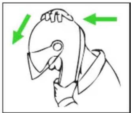
natural_image
Line drawing of a person's head in profile with green arrows indicating direction (no text or symbols)
natural_image
Two people crossed out of a circular object, one holding a tool, with a green diagonal line crossing through (no text or symbols)ISTRUZIONI D'USO
FRONTINO E PUNTALE
CONGRATULATIONS... for the purchase of your new helmet.
This helmet has been designed and created to be a modern, high performing product, able to satisfy the most demanding requests as for safety and comfort. This is made possible by the helmet design, its ergonomic, comfort and aerodynamic properties as well as its practical and easy-to-use controls.
SAFETY AND NORMS OF USE
IMPORTANT
- Before using the helmet read this booklet and all enclosed documents carefully, in that they contain very important indications on how to use the helmet easily and safely.
- Failure to observe these instructions may reduce the protection provided by the helmet and consequently put your safety at risk.
USING THE HELMET
- The helmet has been specifically designed for motorcycle and motorbike use therefore it must not be used for other purposes (or uses or scopes). Equal protection is not guaranteed for any use different from the intended one.
- In case of accident, the helmet represents a protective element, which reduces injuries and head damage. This notwithstanding, it cannot alone prevent serious and/or fatal injuries due to the specific accident dynamics, therefore drive carefully.
- When driving any motorcycle, always wear the helmet properly fastened in order to fully exploit its protection.
- Never wear scarves under the fastening system nor caps of any sort under the helmet.
- The helmet can muffle traffic noises. However make sure that you can hear essential sounds such as horns and emergency vehicle sirens.
- Always keep the helmet away from heat sources like the exhaust muffler, the bag seat or the interior of a vehicle.
- Do not modify nor damage the helmet or part of it for whatsoever reason. Use only original accessories and/or spare parts suitable for your specific helmet model.
- Damage resulting from accidental fall may not be visible; helmets, which received violent impacts, are to be replaced.
- In case of doubt about the helmet integrity and safety, avoid using it and contact an authorized dealer to let it check.
CHOOSING THE HELMET
Size
- In order to determine the correct helmet size, try on helmets of different sizes and choose the one which suits best the shape of your head and which you feel firm once worn and fastened, thus ensuring a great comfort.
- Should the helmet be too big, it may slide down covering the eyes or turn slowly to the side while riding.
- Keep it on for a few minutes and make sure there are no points of extreme pressure that may cause pain or headache.
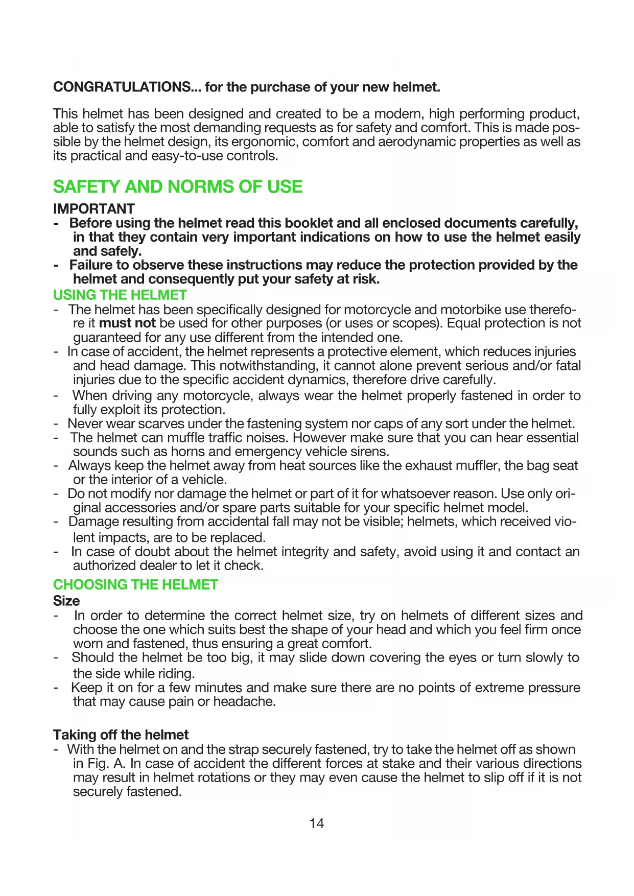
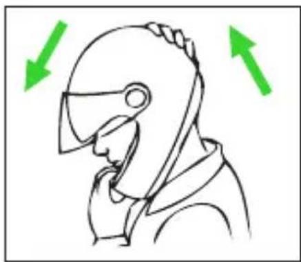
Taking off the helmet
- With the helmet on and the strap securely fastened, try to take the helmet off as shown in Fig. A. In case of accident the different forces at stake and their various directions may result in helmet rotations or they may even cause the helmet to slip off if it is not securely fastened.
- The helmet should not rotate nor move on the head and should not slide off. Should the contrary happen, adjust strap length or change helmet size. Repeat test.
Retention System
- The retention system (strap) is factory-adjusted at a standard length. Before use, check that it is correctly pre-adjusted.
- Make sure the strap is properly fastened and tightened so as to keep the helmet firmly in place. Anyway, before riding, make sure that the strap is well fastened under the chin, as close as possible to the throat, but without being uncomfortable.
- The correct strap tension should allow normal breathing and swallowing, but without leaving the space of a finger between strap and throat.
- Attention: the button which may be present on the strap only prevents its end from flapping once the strap has been fastened properly.
MAINTENANCE AND CLEANING
- Damage resulting from accidental fall may not be visible; helmets, which received violent impacts, are to be replaced.
- Attention: the helmet can be seriously damaged by some common substances without the damage being visible. To clean the helmet, use only lukewarm water and mild soap; dry at room temperature, away from direct sunlight and/or heat sources.
- Attention: never use gasoline, thinner, benzol, solvents or other chemicals as they may irreparably damage the helmet irreparably damage the helmet.
Fig. A
natural_image
Line drawing of a person wearing a helmet with green arrows indicating direction (no text or symbols)
natural_image
Line drawing of a person's head in profile with green arrows indicating motion direction (no text or symbols)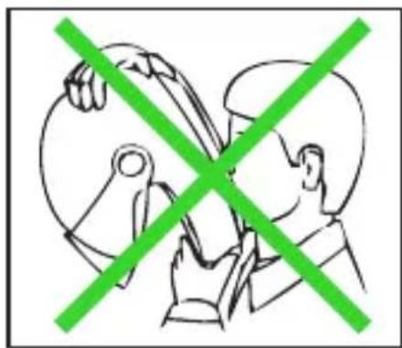
natural_image
Illustration of two people crossed out with a green diagonal line crossing through their eyes (no text or symbols)INSTRUCTIONS FOR USE
PEAK AND PEAK EXTENSION
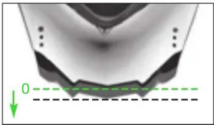
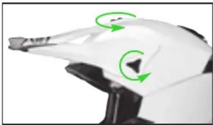
The peak can be adjusted in different positions by turning it upwards or downwards (Fig. 1). It also is equipped with a peak extension that can be adjusted in three different positions. (Fig. 2A).
WARNING
When riding on the road, the peak must be adjusted to the highest position "0" (Fig. 1) and the peak extension must be at the minimum extension position "0" (Fig. 2A).
1.PeakAdjustment
1.1. Loosen the tightness of the upper central threaded cover plate "A" by rotating it counter-clockwise (Fig. 3).
1.2. Rotate the peak on the side cover plates "B" to adjust it to the desired position, which is the highest one when riding on the road (see position "0" in Fig. 1).
1.3. Lock the peak in the desired position by tightening the upper central threaded cover plate "A"; check that the side cover plates "B" are not loose (Fig. 3).
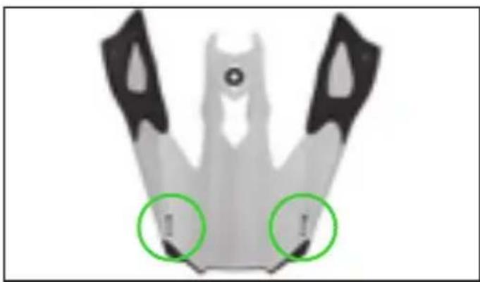
2. Peak Extension Adjustment
2.1. Completely unscrew the internal screws located at both ends of the peak extension (Fig. 2B).
2.2. Remove the extension from the peak; then put it back in one of the three possible positions, which when riding on the road is the one farthest back (see position "0" in Fig. 2A), by inserting its side pins in the specific holes at the two ends of the peak.
2.3. Tighten the internal screws while checking that the peak extension is positioned symmetrically on the peak.
3.PeakDisassembly
3.1. Completely unscrew the threaded side cover plates “B” by rotating them counter-clockwise so that the side ends of the peak detach from the helmet shell (Fig. 3). Pay attention not to lose the two air intakes placed between the peak and the shell (Fig. 2B).
3.2. Completely unscrew the upper central threaded cover plate “A” by rotating it counter-clockwise (Fig. 3). Remove the peak from the helmet, paying particular attention not to lose the trim of the upper central threaded cover plate “A” placed between the peak and the shell (Fig. 2B).
4.PeakAssembly
Check that the air intakes are properly hooked to the peak as they were originally (Fig. 2B).
4.1. Place the trim of the upper central cover plate “A” in line with the threaded hole and place the peak on the shell. Insert the upper central threaded cover plate “A” into the hole and fasten by rotating it clockwise without tightening it completely (Fig. 3).
4.2. Insert the left side cover plate "B" into the relevant seat on the shell and tighten it completely (Fig. 3). Repeat the same operation on the other side of the helmet.
4.3. Complete the adjustment of the position of the peak and its extension as previously described (see steps 1.2., 1.3. and 2.).
WARNING
- Check that the cover plates, internal trim and air intakes, which are interposed between the peak and the helmet shell, keep the peak steady in the desired position.
- Do not use the helmet if the peak and peak extension have not been assembled and adjusted properly.
- Do not install the peak without the internal trim of the cover plates and air intakes.
- In case of malfunctioning or damages, please contact an authorized X-Lite dealer.
REMOVABLE INNER COMFORT PADDING
The removable comfort padding consists of a liner, pads of the side cheek pads (right and left) and covering straps, all completely removable and washable. The cheek pads are also characterised by removable inner expanding foam padding.
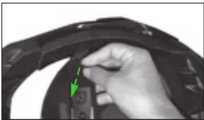
5. Cheek Pad Disassembly
5.1. Unfasten the chin strap (see instructions).
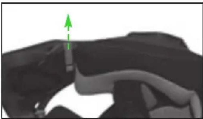
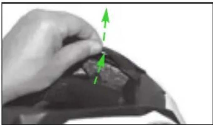
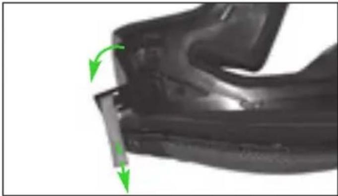
5.2. Gently pull the red strap in the front area of the pad of the left cheek pad to release the safety lever on its back (Fig. 4).
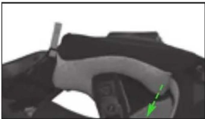
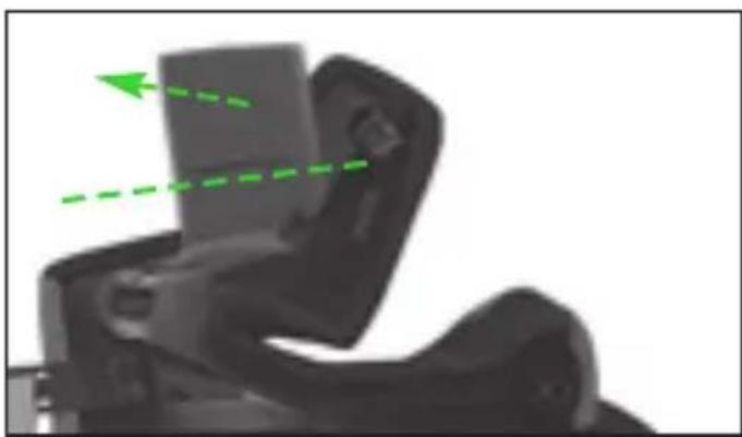
5.3. Hold the front part of the pad of the left cheek pad and turn it upwards to un-hook the front and upper hooks on its back (Fig. 5).
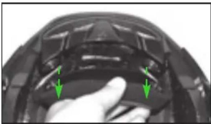
5.4. Pull the back of the pad of the left cheek pad towards the inside of the helmet to undo the snap fastener on its back (Fig. 6).
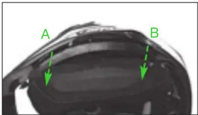
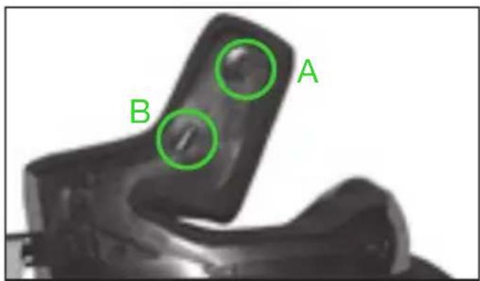
5.5. Pull brackets “A” and “B” of the pad of the left cheek pad upwards to unhook them from the corresponding plates between the outer shell and polystyrene cheek pad (Fig. 7).
5.6. Completely remove the pad of the left cheek pad from the helmet.
5.7. Repeat these steps with the right cheek pad.
Note: Do not remove the polystyrene cheek pads from the helmet shell.
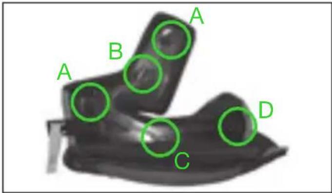
6. Disassembly of the inner expanding foam padding of the cheek pads
To make it easier to wash the inner comfort padding components, the cheek pads of the helmet are fitted with inner expanding foam padding that can be removed from the fabric lining. To remove the padding, proceed as follows after removing the cheek pads from the helmet (see instructions above).
6.1. Unhook the three eyelets of the rear frame of the left cheek pad next to the two hooks "A" (top and front) and snap button "D" (rear) on its back, respectively (Fig. 8).
6.2. Take the top "B" and bottom "C" flaps of the frame out of the respective loops on the back of the frame (Fig. 8).
6.3. Gently remove the inner expanding foam padding from the fabric lining of the cheek pad (Fig. 9).
6.4. Repeat these steps with the right cheek pad.
7. Disassembly of the chin strap covering
To remove the chin strap covering from the strap, proceed as follows after removing the cheek pads from the helmet (see instructions above).
7.1. Pull the left covering strap in line with the "hook and loop fastener" to separate it from the chin strap band and then take it off (Fig. 10A).
7.2. Repeat these steps with the right covering strap.10C
8. Linerdisassembly
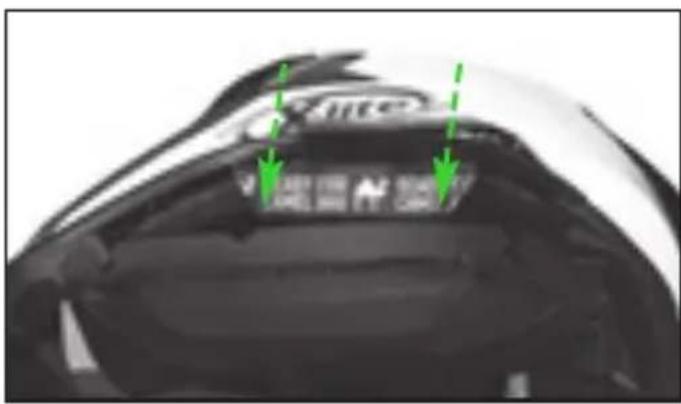
8.1. Pull the back of the comfort padding towards the inside of the helmet to un-hook the two side buttons on its back from their seats on the rear support fixed to the polystyrene inner shell (Fig. 11).
8.2. Unhook the left front flap from the support fixed to the inner shell below the trim of the upper edge of the shell by slightly pulling the comfort padding towards the inside of the helmet (Fig. 12). Repeat the same steps for the central front and right front flaps.
8.3. Completely remove the comfort padding from the helmet.
9. LinerAssembly
9.1. Properly insert the comfort padding into the helmet.
9.2. Slip the left front flap of the liner into its seat by slightly deforming the upper shell sealing edge (Fig. 13). Repeat the same steps for the central front and right front flaps.
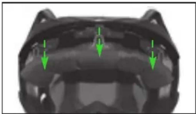
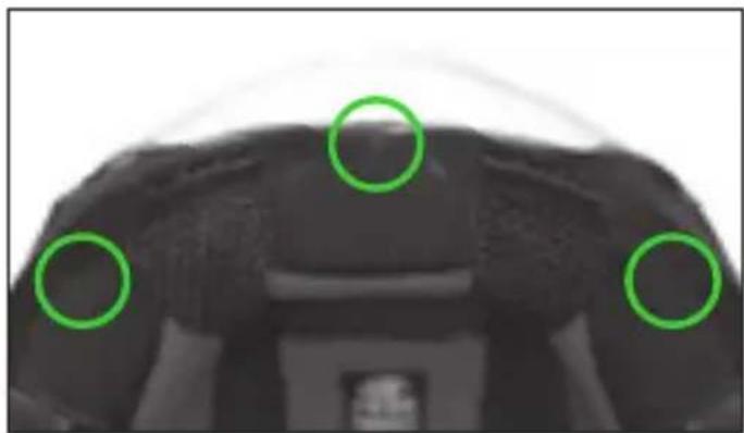
9.3. Correctly turn up the shell sealing edge and press downwards in line with the three front flaps (left, central and right) until they are fully fastened to the support. Make sure that the front helmet area is as shown in Fig. 14.
9.4. Fasten the two side buttons on the back of the rear part of the comfort padding to the corresponding seats on the rear support fixed to the polystyrene inner shell (Fig. 11).
9.5. Spread out the inner comfort padding and make it stick to the inner shell by applying pressure first in the upper zone, so that the hook and loop fastener strap on the top of the inside of the shell grips, and then along the circumference.
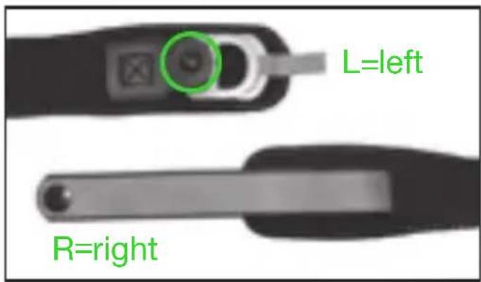
10. Assembly of the chin strap covering
The right and left chin strap covering are different from each other (Fig. 10B).
10.1. After identifying the left covering strap, insert the release mechanism of the chin strap inside of it in line with the free end of the “hook and loop fastener” until it comes completely out from the central slot. Press the free end of the strap over the chin strap band in line with the “hook and loop fastener” and pull the strap to stretch it out completely (Fig. 10A).
10.2. Repeat these steps with the right covering strap.
10.3. Make sure the straps are secured by gently pulling them towards the inside of the helmet.
10.4. If the release mechanism is the D-Ring type, check that the anti-fluttering snap button on the left strap only is correctly placed past the two D-rings (Fig. 10B).
11. Assembly of the inner expanding foam padding of the cheek pads
11.1. Gently put the inner expanding foam padding inside the fabric lining of the left cheek pad (Fig. 9). Carefully spread out the padding while checking that there are no wrinkles in the cheek pad fabric lining.
11.2. Insert the upper "B" and lower "C" flaps of the frame in their loops on the back of the frame (Fig. 8).
11.3. Hook the three eyelets of the rear frame of the left cheek pad near the two "A" hooks (top and front) and snap button "D" (rear) on the back (Fig. 8).
11.4. Repeat these steps with the right cheek pad.
Warning: the rear eyelet with its snap button “D” has a shape different from that of the front and top eyelets and of the corresponding hooks “A”.
12. Cheek Pad Assembly
12.1. Take the pad of the left cheek pad and check that the safety lever on the back is in the opening position (Fig. 15).
12.2. Put the left cheek pad inside the helmet and insert the rear bracket “B” in the corresponding plate between the outer shell and polystyrene cheek pad by pressing until it is fastened (Fig. 7).
12.3. Insert the chin strap in the passageway of the cheek pad padding and press near the rear snap fastener placed on the back to fasten it to the relevant seat on the polystyrene cheek pad (Fig. 6).
12.4. Press the pad of the left cheek pad against the polystyrene cheek pad and at the same time turn it inwards to fasten the front and top hooks on its back. (Fig. 5).
12.5. Press the safety lever upwards in line with the fastening area of the red strap to turn it towards the cheek pad padding until it reaches its closing position. (Fig. 4).
12.6. Check that the fastener and hooks are firmly fastened by slightly pulling the pad of the cheek pad towards the inside of the helmet, then check that it remains adherent to the polystyrene cheek pad.
12.7. Insert front bracket “A” in the corresponding plate between the outer shell and polystyrene cheek pad, then press it until it becomes fastened (Fig. 7). Place the front red strap against the inner surface of the chin guard.
12.8. Repeat these steps with the right cheek pad.
Warning: the buttons are not hooked until a click is heard. Check that the strap comes out properly from the cheek pad padding.
WARNING
- If your helmet is equipped with the double D-Ring retention system, pull it down as indicated in the attached double D-Ring label.
- Remove the inner comfort padding only when cleaning or washing is required.
- Never use the helmet if all parts of the inner comfort padding have not been correctly and completely reassembled.
- Delicately hand-wash in lukewarm water (max. 30°C) and neutral soap.
- Rinse with cold water and allow drying at room temperature, away from direct sunlight.
- Never machine-wash the inner comfort padding.
- The inner polystyrene is an easily deformable material. It is apt to change or get partially destroyed to help absorb shocks.
- Do not modify or alter the helmet's internal polystyrene components in any way.
- Clean the inner polystyrene components with a damp cloth only and allow it to dry at room temperature away from direct sunlight.
- Never use tools or equipment of any sort to carry out the steps described above.
EYEWEAR ADAPTIVE
13. Creating space for glasses
13.1. Remove the left cheek pad from the helmet (see instructions above).
13.2. Unhook the rear frame eyelet of the cheek pad in line with the top hook "A" shown on its back (Fig. 16).
13.3. Take the top flap "B" of the frame out of the loop on the back of the frame (Fig. 16).
13.4. Gently remove the inner expanding foam padding from the fabric lining of the cheek pad (Fig. 17).
13.5. Remove the upper part of the inner pre-punched padding (Fig. 17), then correctly put back the remaining padding part in the cheek pad.
NOTE: it is recommended to keep the removed padding for any subsequent reuse.
13.6. Put the top flap "B" of the frame back in the loop on the back of the cheek pad and refasten the eyelet in line with the top hook "A" on the back (Fig. 16).
13.7. Refit the complete cheek pad on the helmet (see instructions above).
13.8. Repeat these steps with the right cheek pad.
14. Removing space for glasses
14.1. Remove the left cheek pad from the helmet (see instructions above).
14.2. Unhook the rear frame eyelet of the cheek pad in line with the top hook "A" shown on its back (Fig. 16).
14.3. Take the top flap "B" of the frame out of the loop on the back of the frame (Fig. 16).
14.4. Properly insert part of the previously removed padding in the fabric lining of the cheek pad (Fig. 17).
14.5. Put the top flap "B" of the frame back in the loop on the back of the cheek pad and refasten the eyelet in line with the top hook "A" on the back (Fig. 16).
14.6. Refit the complete cheek pad on the helmet (see instructions above).
14.7. Repeat these steps with the right cheek pad.
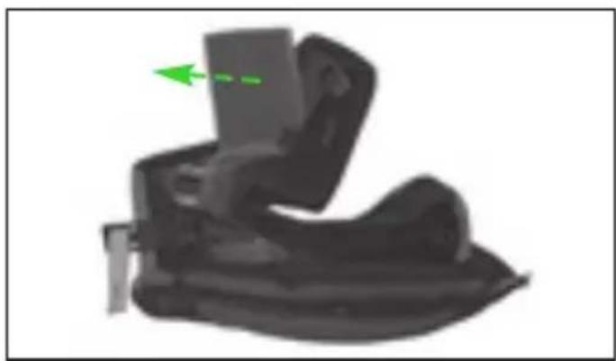
NOLAN EMERGENCY RELEASE SYSTEM
The Nolan Emergency Release System (NERS) allows the rescue personnel to remove the pads of the cheek pads from the helmet while it is still on the rider's head.
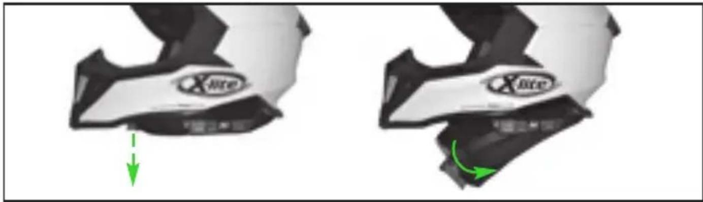
To remove the pad of the left cheek pad from the helmet, unfasten the chin strap and then pull the red strap in the front area of the pad as shown in Fig. 18.
The safety lever placed on the back of the pad of the cheek pad will first release and then, while continuing to pull the red strap, the pad will release from the polystyrene and gradually turn toward the outside of the helmet, leaving its side area free.
Repeat the same step on the right side of the helmet, which can then be more easily removed from the rider's head.
WARNING
- Never pull the red straps of the Nolan Emergency Release System (NERS) while riding.
- Always check that the cheek pads are properly installed. After using the Nolan Emergency Release System (NERS), check that the cheek pads are not damaged and reassemble them following the instructions above.
- Do not use the Nolan Emergency Release System (NERS) for the routine cheek pad maintenance and cleaning operations.
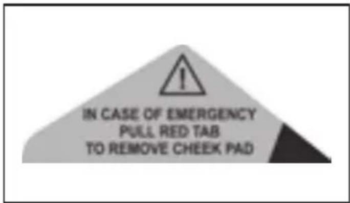
- Do not take the stickers shown in Fig. 19 off the helmet as they could provide useful information to rescue personnel.
- Should the Nolan Emergency Release System (NERS) fail or be damaged, please refer to an X-Lite authorized dealer.
- Use the Nolan Emergency Release System (NERS) for providing aid only if you have proven expertise and qualifications in the field. If in doubt, call the appropriate emergency personnel.
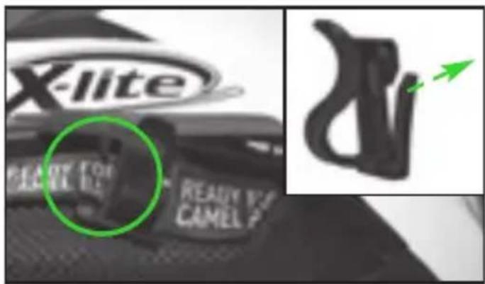
"CAMEL BAG" ARRANGEMENT FOR THE HYDRATION SYSTEM
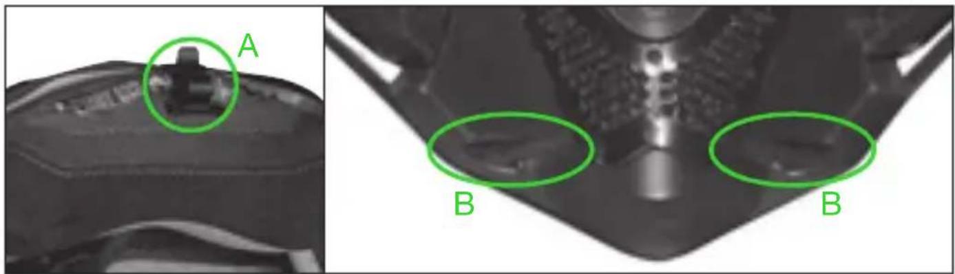
The helmet is designed to facilitate installation of a hydration system (not supplied) and fastening its hose. It includes (Fig. 20):
- a side hose clip “A”, on the “READY FOR CAMEL BAG” strap, useful for fastening the hydration system hose;
- a deformable seat "B" on the lower edge of the inner chin guard for positioning the end of the hose with the suction valve near the mouth.
The “READY FOR CAMEL BAG” strap and the deformable seat “B” are on both sides of the helmet.
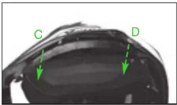
If you do not use a hydration system, we recommend removing hose clip “A” (see instructions below) and positioning the “READY FOR CAMEL BAG” straps behind the pads of the removable cheek pads. To do so, pull the bottom part of the pad of the left cheek pad upwards to release brackets “C” and “D” from the corresponding plates between the outer shell and the polystyrene cheek pad (Fig. 21).
Then place the “CAMEL BAG” strap against the polystyrene cheek pad (Fig. 22).
Afterwards insert brackets “C” and “D” in the corresponding plates between the outer shell and the polystyrene cheek pad, then press until they are fastened (Fig. 21).
Repeat these steps with the right cheek pad.
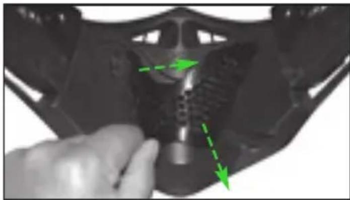
15. Hydration system hose assembly
To fasten the hydration system hose, slightly buckle the free part of side hose clip "A" and put the hose inside it. Then buckle seat "B" of the inner chin guard and insert the initial part of the hose with the suction valve inside it. Adjust the length of the hose by sliding it into housings "A" and "B" and continue to assemble the hydration system following the relevant instructions and recommendations provided by its manufacturer.
16. Hydration system hose disassembly
To disassemble the hydration system hose, slip off its initial part by buckling seat “B” of the inner chin guard. Then remove the hose from side hose clip “A” while buckling it slightly.
17. Hose clip disassembly
To remove fastening side hose clip “A” from the “READY FOR CAMEL BAG” strap, buckle its side parts and remove them from the strap (Fig. 23).
18. Hose clip assembly
To assemble side hose clip “A” on the “READY FOR CAMEL BAG” strap, insert first one and then the other deformable side part of the clip under the “READY FOR CAM-EL BAG” strap until they are completely fastened while taking care to position the free and deformable fastening part of the hose facing upward (Fig. 20).
WARNING
- Do not use for any reason the “READY FOR CAMEL BAG” straps and/or the hose clip for any purpose other than those described above.
-
Always check that the side hose clip does not become entangled with clothing or obstructs movement of the head and helmet, which must always be free. Verify this by wearing all your clothing, including any neck and/or body braces and protectors normally used in off-road sports. If necessary, remove the side hose clip from the helmet.
-
Remove the side hose clip and fold back the “READY FOR CAMEL BAG” strap if a hydration system is not used.
- Fasten the side hose clip only to the "READY FOR CAMEL BAG" strap.
- Do not fasten the side hose clip to the cheek pads and/or removable padding.
- Do not modify or tamper with the helmet components to install the hydration system. Check that the hydration system hose is compatible with the hose clip and deformable seat of the chin guard.
- In case of doubt, malfunctioning or damage, please contact an X-Lite authorized dealer.
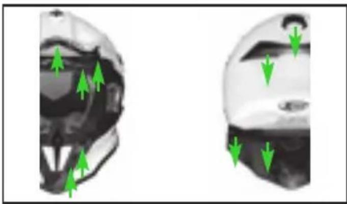
VENTILATION SYSTEM
The ventilation system of the helmet (Fig. 24) consists of:
Upper air intakes: the two openings located under the peak capture and channel the air, directing it dispersion-free in the upper area of the rider's head.
Front air intakes: also with the contribution of the side conveyors, two openings located under the peak capture and channel the air, directing it dispersion-free in the front area of the rider's head. Another two openings are in the front area, near the sealing edge of the window opening.
Chin guard air intake: provides ventilation in the mouth area while filtering its content.
Air extractors: located on the upper rear part of the helmet, in line with the rear base edge and on the sides of the helmet so that warm and stale air can flow out, thus ensuring optimum comfort inside the helmet.
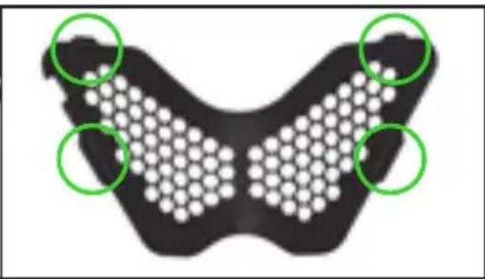
CHIN GUARD AIR INTAKE FILTERS
The chin guard air intake is fitted with a fixed external filter in metal mesh that allows easy air intake while limiting the entry of insects or small stones, and a second removable internal filter assembled in the inner chin guard that can be removed from its housing to increase the flow rate of the air intake and/or to be washed.
19. Disassembly of the removable internal filter
To remove the removable internal filter, pry its holding frame towards the inside of the helmet near the upper right corner of the frame. Unfasten the holding frame from the deformable internal chin guard by slipping the fastening flaps out of the slots on the internal chin guard.
Completely remove the holding frame from the chin guard and pull the filter out from its housing in the internal chin guard.
Then reassemble the filter holding frame on the internal chin guard by inserting, one by one, the side and then upper fastening flaps of the frame in the corresponding slots on the internal chin guard applying light pressure above (Fig. 25).
20. Assembly of the removable internal filter
To replace the removable internal filter, remove its holding frame as explained above, insert it and place it properly in its housing in the chin guard. Then reassemble the holding frame as explained above (Fig. 25).
WARNING
- If you wish to use the helmet without the removable internal filter, it is recommended to always install the filter holding frame.
natural_image
Line drawing of a person wearing a helmet with green arrows indicating direction (no text or symbols)
natural_image
Line drawing of a bird's head in profile with green arrows indicating direction (no text or symbols)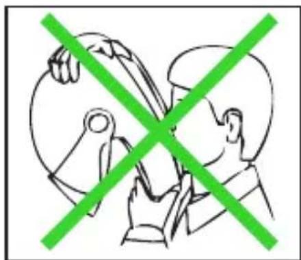
natural_image
Two people crossed out of a circular object, one holding a tool, with no visible text or symbols.GEBRAUCHSANLEITUNG
natural_image
Line drawing of a person in profile view with green arrows indicating direction (no text or symbols)
natural_image
Line drawing of a person's head in profile with green arrows indicating movement or force direction (no text or symbols)
natural_image
Illustration of two people crossed out with a green diagonal line crossing through their face (no text or symbols)INSTRUCTIONS D'UTILISATION
VISIÈRE ET CASQUETTE
natural_image
Line drawing of a person in profile view with green arrows indicating direction (no text or symbols)
natural_image
Line drawing of a person's head in profile with green arrows indicating movement or direction (no text or symbols)
natural_image
Two people crossed out of a circular object, one holding a tool, with a green diagonal line crossing through (no text or symbols)INSTRUCCIONES DE USO
VISERA Y EXTENSIÓN
natural_image
Line drawing of a person in profile view with green arrows indicating direction (no text or symbols)
natural_image
Line drawing of a bird's head in profile with green arrows indicating direction (no text or symbols)
natural_image
Two people crossed out of a circular object, one holding a tool, with a green diagonal line crossing through (no text or symbols)natural_image
Line drawing of a person in profile with green arrows indicating direction (no text or symbols)
natural_image
Line drawing of a person's head in profile with green arrows indicating movement or force direction (no text or symbols)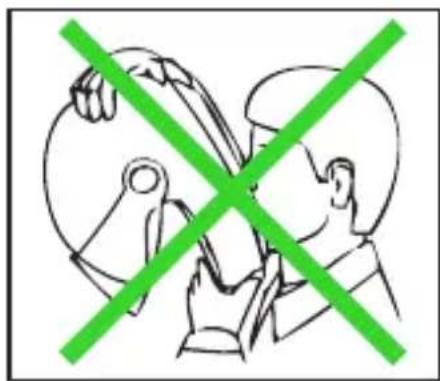
natural_image
Two people crossed out of a circular object, one holding a tool, with a green diagonal line crossing through (no text or symbols)GEBRUIKSAANWIJZING
KLEP EN VERLENGSTUK
natural_image
Line drawing of a person wearing a helmet with green arrows indicating direction (no text or symbols)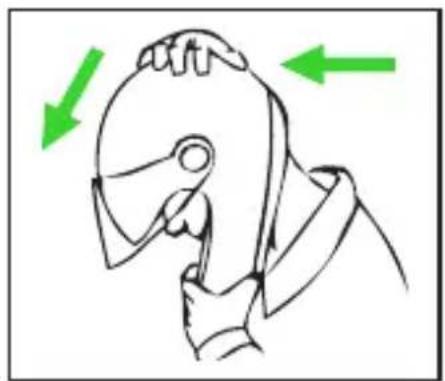
natural_image
Line drawing of a person's head in profile with green arrows indicating movement or force direction (no text or symbols)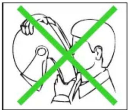
natural_image
Two people crossed out of a circular object, one holding a tool, with a green X symbol (no text or labels)BRUGERVEJLEDNING
FRONTSTYKKE OG SPIDS
natural_image
Line drawing of a person wearing a helmet with green arrows indicating direction (no text or symbols)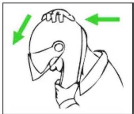
natural_image
Line drawing of a person's head in profile with green arrows indicating motion direction (no text or symbols)
natural_image
Illustration of two people crossed with a green diagonal line, no text or symbols presentΟΔΗΓΙΕΣ ΧΡΗΣΗΣ
ΓΕΙΣΟ ΚΑΙ ΠΟΡΠΗ
natural_image
Two identical helmet designs shown in side and front views, with a green arrow indicating direction (no text or symbols)Fig. 1
natural_image
Abstract grayscale shape with dotted elements and a green dashed line labeled '0' (no text or symbols beyond the label)Fig. 2A
natural_image
Close-up of a mechanical component with two green circular annotations highlighting features (no text or symbols present)Fig. 2B
natural_image
Close-up of a white robotic arm with green circular arrows indicating motion or movement (no text or symbols)Fig. 3
natural_image
Close-up of a mechanical component with a green arrow indicating upward motion (no text or symbols)Fig. 4

natural_image
Close-up of a mechanical component with a green arrow indicating rotation (no visible text or symbols)Fig. 5
natural_image
Close-up of a mechanical component with a green arrow pointing to a specific part (no visible text or symbols)Fig. 6
text_image
A BFig. 7
text_image
A B A C DFig. 8
natural_image
3D rendered object resembling a vehicle or device with a green arrow indicating direction (no text or symbols)Fig. 9
natural_image
Close-up of a hand adjusting a car wheel rim with a green arrow pointing to the handle (no text or symbols visible)Fig. 10A
text_image
L=left R=rightFig. 10B
natural_image
Close-up of a hand holding a black helmet with green arrows pointing to the interior (no text or symbols visible)Fig. 11
natural_image
Close-up of a mechanical component with green arrows pointing to features, no visible text or symbolsFig. 12
natural_image
Close-up of a hand holding a small object with green arrows indicating direction (no text or symbols)Fig. 13
natural_image
Close-up of a mechanical component with three green circular annotations highlighting specific features (no text or symbols present)Fig. 14
natural_image
Close-up of a mechanical component with green arrows indicating motion or force direction (no text or symbols visible)Fig. 15
text_image
A BFig. 16
natural_image
Close-up of a mechanical component with green dashed lines indicating motion or alignment (no text or symbols)Fig. 17
natural_image
Two identical XLite shoe designs showing a green arrow pointing to a component, no text or symbols present.Fig. 18
text_image
IN CASE OF EMERGENCY PULL RED TAB TO REMOVE CHEEK PADFig. 19
natural_image
Medical imaging comparison showing a device labeled 'A' and two green circles labeled 'B' (no text or symbols beyond labels)Fig. 20
text_image
C DFig. 21
text_image
Close-up of a motorcycle's head with green arrows pointing to specific parts, including '安全阀' and '风扇位置'Fig. 22
text_image
X-lite BEET FOR CAMEL PFig. 23
natural_image
Two identical helmet designs with green arrows pointing to internal features, no text or symbols present.Fig. 24
natural_image
Close-up of a hand adjusting a mechanical component with green arrows indicating direction (no text or symbols visible)Fig. 25
natural_image
Diagram of a butterfly-shaped object with white hexagonal patterns and three green circles highlighting specific regions (no text or symbols present)Note, Clipboard, Notizen, Notas, vóteç
- Questo casco è prodotto in uno stabilimento che rispetta l'ambiente. Al termine del suo utilizzo, si raccomanda di effettuarne lo smaltimento, seguendo le specifiche normative di legge vigenti nel luogo o Paese di residenza.
- This helmet is manufactured in a plant respecting the environment. At the end of its use, it is recommended to dispose of it according to specific regulations in force over the place or Country of residence.
- Dieser Helm wurde mit größtmöglicher Rücksicht auf die Umwelt hergestellt. Nach Gebrauch entsorgen Sie ihn bitte entsprechend den landes- oder ortsüblichen Bestimmungen.
- Ce casque est fabriqué dans un établissement qui respecte l'environnement. À la fin de son utilisation, il est recommandé de procéder à son élimination, suivant les règles spécifiques en vigueur dans le lieu ou le pays de résidence.
- Este casco ha sido fabricado en una instalación industrial que respeta el medio ambiente. Una vez cumplido su servicio, para eliminarlo, se recomienda acudir a un centro de recogida selectiva y actuar según las normas vigentes en el lugar y país de residencia.
- Este capacete é produzido numa fábrica que respeita o ambiente. No final da sua utilização, recomenda-se que seja eliminado de acordo com regulamentação específica em vigor no local ou País de residência.
- Deze helm wordt op een milieu vriendelijke manier vervaardigd. Wanneer de helm niet meer gebruikt wordt dient u deze helm af te voeren volgens de geldende milieu eisen.
- Denne hjelm er lavet med respekt for miljøet. Når den engang skal bortskaffes, bør det være i overensstemmelse med miljøreglerne.
• Το κρανος αυτο εχει κατασκευαστει σε εργοστασιο που σεβεται το περιβαλλον. Μετα το περας της χρησης του συνισταται να το καταστρεψετε συμφωνα με τους κανονισμους που ισχυουν στο τοπο ή χωρα διαμονης σας.
NOIAN Technology
COMPOSITE FIBRE
| ISTR000000133 - 09.2016 (Eletta) |