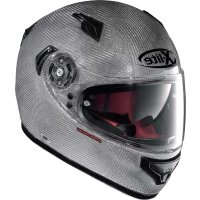
N21 Visor Moto GP Legend - Motorcycle helmet Nolan - Free user manual and instructions
Find the device manual for free N21 Visor Moto GP Legend Nolan in PDF.
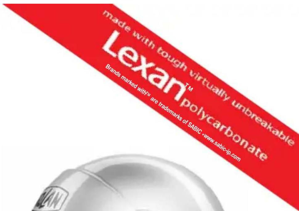
| Product Type | Full-face motorcycle helmet |
| Brand | Nolan |
| Model | N21 Visor Moto GP Legend |
| Size | Available in multiple sizes (XS to XXL per Nolan standard) |
| Shell material | Polycarbonate (estimated) |
| Visor | Scratch-resistant, tool-free removable |
| Sun visor (VPS) | Integrated Vision Protection System in scratch-resistant LEXAN polycarbonate, operated by side slider |
| Retention system | Chin strap with micrometric buckle |
| Comfort | Removable and hand-washable inner foam |
| Safety | Approved according to ECE 22-05 standard |
| Maintenance | Clean with lukewarm water and neutral soap; dry at room temperature away from sunlight |
| Accessories | Side plates with interchangeable colored frame; Helmet Lock Ring for hanging |
| Repairability | Spare parts available from authorized Nolan dealers |
| Usage | For motorcycle and moped riding only |
| Weight | Approximately 1400 g (estimated) |
Frequently Asked Questions - N21 Visor Moto GP Legend Nolan
User questions about N21 Visor Moto GP Legend Nolan
0 question about this device. Answer the ones you know or ask your own.
Ask a new question about this device
Download the instructions for your Motorcycle helmet in PDF format for free! Find your manual N21 Visor Moto GP Legend - Nolan and take your electronic device back in hand. On this page are published all the documents necessary for the use of your device. N21 Visor Moto GP Legend by Nolan.
USER MANUAL N21 Visor Moto GP Legend Nolan
facebook.com/NolanGroup
text_image
made with tough virtually unbreakable Lexan™ polycarbonate Brands marked with™ are trademarks of SABIC •www.sabic-ip.com
natural_image
Front view of a white and black sports helmet with visor and front-mounted sensor (no visible text or symbols)SICUREZZA E ISTRUZIONI D'USO
SAFETY AND INSTRUCTIONS FOR USE
natural_image
Line drawing of a person in profile wearing a helmet, with red arrows indicating direction (no text or symbols)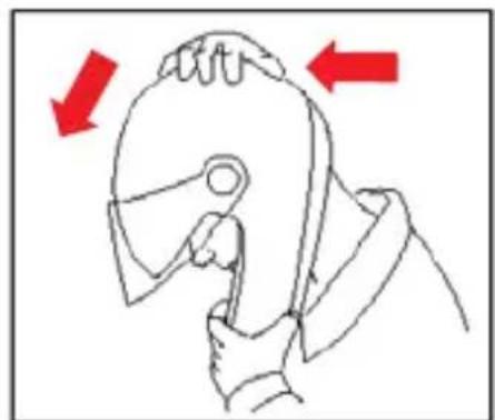
natural_image
Line drawing of a hand gripping a tool, with red arrows indicating direction (no text or symbols)
text_image
Diagram showing two hands crossed out of a device with a red prohibition symbol, indicating no protection or exclusion.ISTRUZIONI D'USO
VISIERA
CONGRATULATIONS... for the purchase of your new helmet.
This helmet has been designed and created to be a modern, high performing product, able to satisfy the most demanding requests as for safety and comfort. This is made possible by the helmet design, its ergonomic, comfort and aerodynamic properties as well as its practical and easy-to-use controls.
SAFETY AND NORMS OF USE
IMPORTANT
- Before using the helmet read this booklet and all enclosed documents carefully, in that they contain very important indications on how to use the helmet easily and safely.
- Failure to observe these instructions may reduce the protection provided by the helmet and consequently put your safety at risk.
USING THE HELMET
- The helmet has been specifically designed for motorcycle and motorbike use therefore it must not be used for other purposes (or uses or scopes). Equal protection is not guaranteed for any use different from the intended one.
- In case of accident, the helmet represents a protective element, which reduces injuries and head damage. This notwithstanding, it cannot alone prevent serious and/or fatal injuries due to the specific accident dynamics, therefore drive carefully.
- When driving any motorcycle, always wear the helmet properly fastened in order to fully exploit its protection.
- Never wear scarves under the fastening system nor caps of any sort under the helmet.
- The helmet can muffle traffic noises. However make sure that you can hear essential sounds such as horns and emergency vehicle sirens.
- Always keep the helmet away from heat sources like the exhaust muffler, the bag seat or the interior of a vehicle.
- Do not modify nor damage the helmet or part of it for whatsoever reason. Use only original accessories and/or spare parts suitable for your specific helmet model.
- Damage resulting from accidental fall may not be visible; helmets, which received violent impacts, are to be replaced.
- In case of doubt about the helmet integrity and safety, avoid using it and contact an authorized dealer to let it check.
CHOOSING THE HELMET
Size
- In order to determine the correct helmet size, try on helmets of different sizes and choose the one which suits best the shape of your head and which you feel firm once worn and fastened, thus ensuring a great comfort.
- Should the helmet be too big, it may slide down covering the eyes or turn slowly to the side while riding.
- Keep it on for a few minutes and make sure there are no points of extreme pressure that may cause pain or headache.
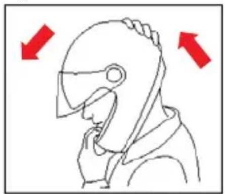
Taking off the helmet
- With the helmet on and the strap securely fastened, try to take the helmet off as shown in Fig. A. In case of accident the different forces at stake and their various directions may result in helmet rotations or they may even cause the helmet to slip off if it is not securely fastened.
- The helmet should not rotate nor move on the head and should not slide off. Should the contrary happen, adjust strap length or change helmet size. Repeat test.
Retention System
- The retention system (strap) is factory-adjusted at a standard length. Before use, check that it is correctly pre-adjusted.
- Make sure the strap is properly fastened and tightened so as to keep the helmet firmly in place. Anyway, before riding, make sure that the strap is well fastened under the chin, as close as possible to the throat, but without being uncomfortable.
- The correct strap tension should allow normal breathing and swallowing, but without leaving the space of a finger between strap and throat.
- Attention: the button which may be present on the strap only prevents its end from flapping once the strap has been fastened properly.
VISOR
- If the visor is damaged or deeply scratched causing reduced visibility, this means that the protective treatment is probably damaged so the visor is to be replaced.
- The visor can be used only for the intended helmet model.
- Do not paint nor apply stickers.
MAINTENANCE AND CLEANING
- Damage resulting from accidental fall may not be visible; helmets, which received violent impacts, are to be replaced.
- Attention: Helmet and visor may be seriously damaged by some common substances without the damage being however visible. Use only lukewarm water and mild soap to clean helmet and visor, and then let them dry at room temperature away from sunrays and/or heat sources.
-
Attention: Never use petrol, thinner, benzene, solvents nor other chemicals which may:
-
Irreparably damage the helmet;
- Modify optical properties, reduce mechanical ones and weaken the visor protective treatment.
Fig. A
natural_image
Line drawing of a person in profile wearing a helmet, with red arrows indicating direction (no text or symbols)
natural_image
Illustration of a hand holding a tool, with red arrows indicating direction (no text or symbols)
text_image
Prohibition sign with red X symbol crossed over a cartoon figure holding a phone, indicating no text or symbols beyond the prohibition.INSTRUCTIONS FOR USE
VISOR
1. Visor Disassembly
1.1. Close the visor and remove the side plate from the helmet by pulling the upper end outwards (Fig. 1).
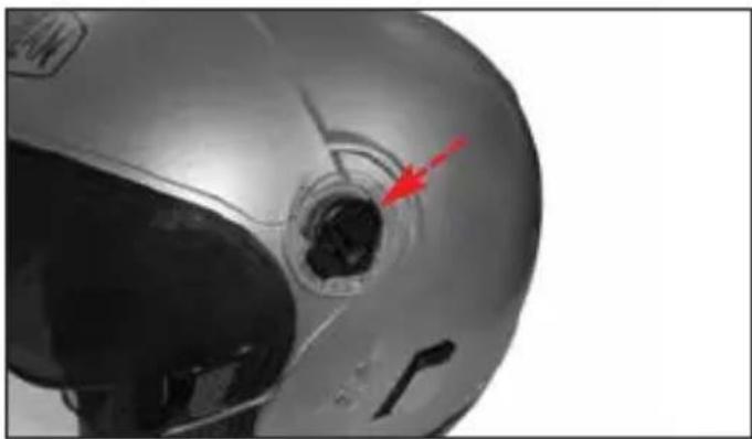
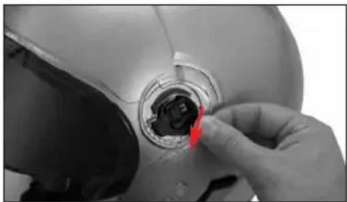
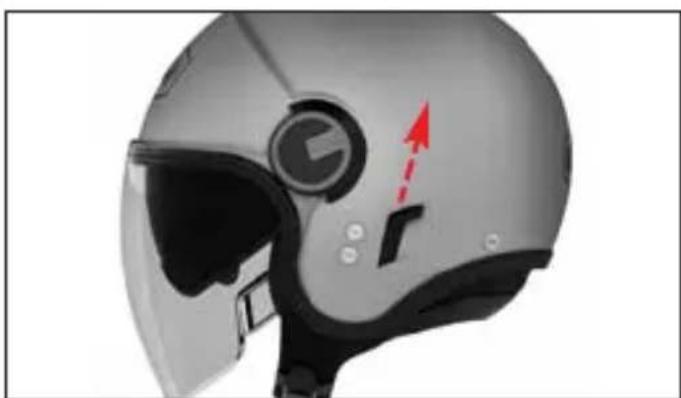
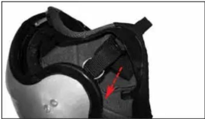
1.2. Push the visor mechanism slider forwards as shown by the arrow (Fig. 2).
1.3. Lift the rear area of the visor from the shell until it is completely released from the mechanism; slightly push it towards the front of the helmet (Fig. 3).
1.4 Repeat all the operations on the other side as well.
2. Visor Assembly
2.1. Place the visor on the shell taking care to align the teeth seat with the front part of the mechanism; hook the visor under the mechanism by pressing it against the helmet in the teeth area and simultaneously pushing it towards the rear part of the helmet so as to completely hook it to the mechanism (Fig. 3).
2.2. Move the slider backwards until you hear the fastening click (Fig. 2).
2.3. Assemble the side plate taking care to centre the internal hooks in the relative seats on the mechanism and pressing until you hear the fastening click (Fig. 4).
2.4. Repeat the operations on the other side as well.
NOTE: The left and right side plates are different from each other and are marked on their back as R (Right) and L (Left).
WARNING
- Make sure that the mechanisms are working properly. Open and close the visor making sure that the mechanisms hold it in the different positions. If necessary, repeat the above-mentioned steps.
- Do not use the helmet if the visor and the side plates have not been assembled properly.
- Do not remove the side mechanisms from the shell.
- Should any of the side mechanisms fail or be damaged, please refer to a Nolan authorized dealer.
SIDE PLATES FRAMES
The side plates are equipped with a coloured frame that can be removed.
3. Side Plates Frame Disassembly
To remove the frame from a side plate first remove the side plate from the helmet (see instructions above).
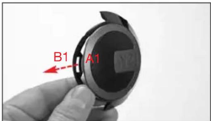
3.1. Pull the front part of the frame forward (and then inward), slightly deforming it, to release the plate front grip pawl A1 from its seat B1 on the frame (Fig. 5).
3.2. Push back the frame to release its three back fastenings C1, C2 and C3 from their seats D1, D2 and D3 on the side plate (Fig. 6) and finally disconnect the frame and the plate.
NOTE: The left and right side plates frames are different from each other and are marked on their back as R (Right) and L (Left).
4. Side Plates Frame Assembly
4.1. Insert the right or left side plate front part on the relevant left of right frame so as the plate front grip pawl A1 overlaps its seat B1 on the frame.
4.2. Hook the frame back fastenings C1, C2 and C3 one by one to their seats D1, D2 e D3 on the side plate slightly deforming the frame (Fig. 6).
4.3. Hook the side plate grip pawl A1 to its seat B1 on the frame slightly deforming it (Fig. 5).
4.4. Make sure that the two components are correctly attached to each other. Then reassemble the side plate on the helmet (see instructions above)
WARNING
- Make sure that the mechanisms are working properly. Open and close the visor, making sure that the side plates and the frames hold their positions. If necessary, repeat the above-mentioned steps.
- Do not use the helmet if the visor and/or the side plates and/or their frames have not been assembled properly.
- If the side plates and/or the frames and/or the side mechanisms are damaged or malfunctioning, refer to a Nolan authorized dealer..
VISION PROTECTION SYSTEM (VPS)
The exclusive inner VISION PROTECTION SYSTEM (VPS) is a LEXAN ^TM(*) - polycarbonate moulded sunscreen with scratch-resistant treatment. Using it is very simple and practical: Just lower it to activate it or lift it to remove it from the field of vision. It is useful in all sorts of situations, both on long journeys out of town and shorter town trips.
VPS Operation
The VPS mechanism allows activating the sun screen by simply lowering it until it partially covers the visor field of vision. In this way, the desired light transmittance reduction is achieved. At any time, without operating the visor, the VPS can be deactivated with a simple movement and easily lifted up to restore the normal conditions of visibility and protection guaranteed by the approved helmet visor.
To deactivate the VPS, push the side slider completely downwards (Fig. 7 A).
To activate the VPS, push the side slider completely upwards (Fig. 7 B).
Precautions for Use
The current approval standards (ECE22-05) state that the visor minimum light transmittance levels must be greater than 80% when riding at night and not less than 50% when riding during the day. For this reason, under particularly bright weather conditions, e.g. very strong sunlight caused by high intensity and/or incidence of the
sunbeams, the use of sunglasses - which entail a transmittance much lower than 50% - turns out to be advisable, if not absolutely necessary. This in order to reduce eye fatigue on long trips. Sunglasses also reduce the risk of direct dazzling as opposed to the use of mere approved helmet visors. However, the use of sunglasses makes it difficult to perform emergency manoeuvres when the maximum visibility range of the helmet visor must be quickly restored. Just think, for example, of what happens when you enter a tunnel or when unexpected changes in environmental brightness occur. Thanks to its operating mechanism, the VPS makes these operations much easier.
WARNING
- The VPS can be used only during the day and under the environmental conditions described before.
- At night and/or in poor visibility conditions, the VPS must be deactivated.
- Always check that the VPS is properly positioned according to the different weather/environmental conditions and/or to the above mentioned recommendations for use.
- We recommend using the VPS only and solely together with the approved standard visor, which has a transmittance value greater than 80%.
- The VPS does not replace the protection guaranteed by the visor.
- Always make sure that the VPS is clean and that it is operating properly in order to avoid scratches and/or anomalous wear on it every time it is activated.
- As for VPS and visor maintenance and cleaning operations, please refer to the appropriate section in the helmet user's manual.
5. VPS Disassembly
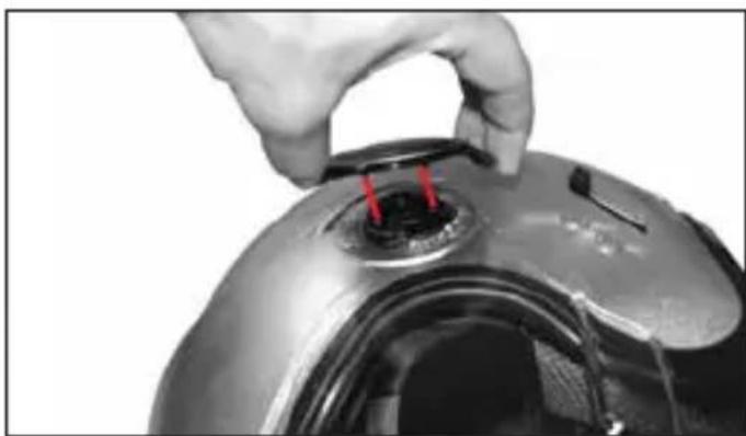
To remove the sunscreen from the helmet, open the visor completely and lower the VPS by pushing the slider completely upwards (Fig. 7 B).
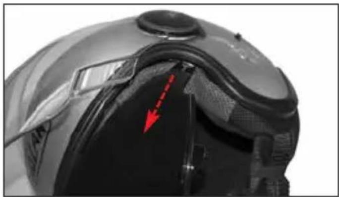
Hold the left lateral part of the sun screen and pull it toward the outside of the helmet (Fig. 8). Repeat the same operation on the right side of the helmet.
6. VPS Assembly
To remove the sunscreen, open the visor completely and push the slider completely upwards (Fig. 7 B).
Insert the sun screen left end into the left side guide until the grip pawl is hooked in shell housing (Fig. 8). Repeat the same operation on the right side of the helmet.
WARNING
- Push the left side slider completely downwards (Fig. 7 A) and upwards (Fig. 7 B) to make sure that the VPS works properly. If necessary, repeat the above-mentioned steps.
- If the VPS opening/closing mechanisms are damaged or not working properly, please contact a Grex authorized dealer.
- Do not use the helmet if the VPS has not been assembled properly.
- Since the VPS does not assure you the same protection as the one provided by the visor, it has to be used only when the helmet visor is lowered.
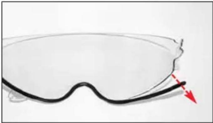
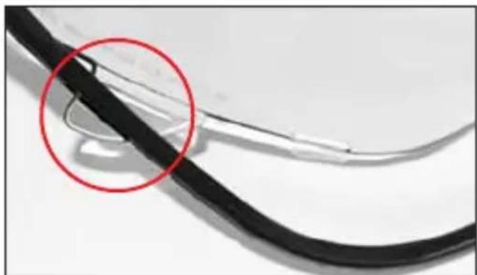
VPS LOWER EDGE TRIM
The lower VPS sunscreen profile is moulded with a printed trim attached to the visor with fastening elements.
7. VPS Trim Disassembly
To release the trim from the lower edge of the sunscreen, first remove the sunscreen from the helmet (see instructions above).
7.1. Pull the trim right end downwards to release the first fastening from the sunscreen (Fig. 9).
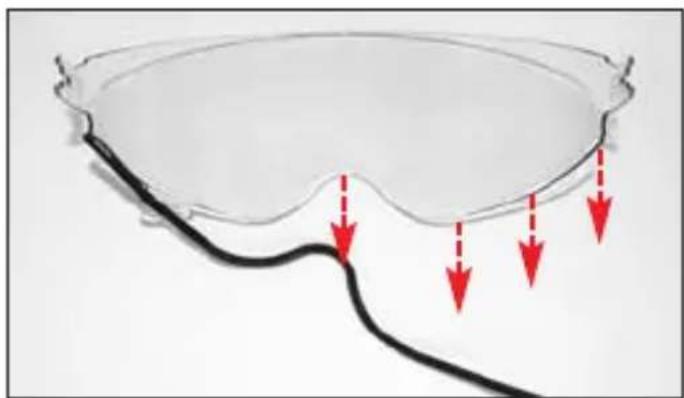
7.2. Continue releasing the other fastenings one by one, moving towards the other end of the sunscreen (Fig. 10).
7.3. Pull out the trim from the sunscreen left side flap (Fig. 10).
7.4. Release the trim left end and completely remove it from the sunscreen (Fig. 11).
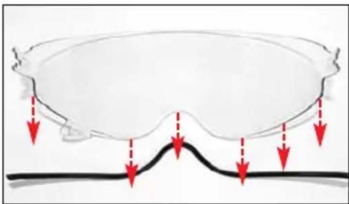
8. VPS Trim Assembly
8.1. Insert the left side flap of the sunscreen in its slot on the trim (Fig. 12).
8.2. Press the trim left end against the sunscreen to attach it to the relevant fastening element (Fig. 10).
8.3. Continue attaching the other fastenings one by one, moving towards the other end of the sunscreen (Fig. 10).
8.4. Press the trim right end against the sunscreen to attach it to the relevant fastening element (Fig. 9).
8.5. Push the trim against the sunscreen aligning it with all the fastening device in order to attach it evenly along the whole sunscreen lower edge; check that all the fastening devices are correctly attached and that the trim and the visor fit together tightly. Finally, fit the sunscreen on the helmet (see instructions above).
WARNING
- Never use the helmet without having correctly assembled the sunscreen trim
- Make sure the VPS operates correctly by moving the left side slider downwards (Fig. 7A) and upwards (Fig. 7B) and check that the visor lower edge trim does not come out of the sunscreen. If necessary, repeat the above-mentioned steps.
- In case of malfunctioning or damages, please contact an authorized Nolan dealer.
REMOVABLE INNER COMFORT PADDING
9. Inner Comfort Padding Disassembly
To remove the inner comfort padding, lift the VPS and open the visor completely (see instructions above).
9.1. Open the chin strap (see specific instructions).
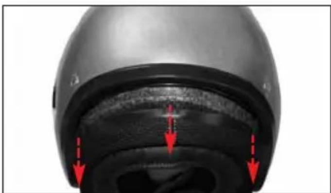
9.2. Hold the left front part of the liner and pull it upwards in order to remove the liner flap from the support fixed to the polystyrene inner shell (Fig. 13). Then repeat the same steps for the central front and right flap.
9.3. Remove the left and right sides of the comfort padding from the cavity between the inner polystyrene shell, the outer shell and the VPS side guides (Fig. 14).
9.4. Unhook the left rear flap of the liner from the support fixed to the polystyrene inner shell by slightly pulling the comfort padding towards the inside of the helmet (Fig. 15). Then repeat the same steps for the central and right flap.
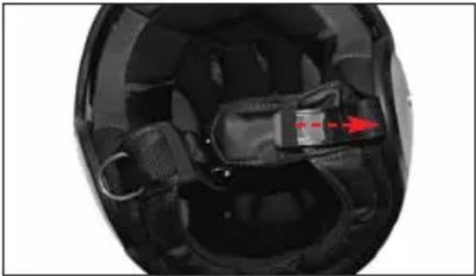
9.5. Remove the chin straps from the elastic loops on the straps and the from the liner side slots (Fig. 16A)..
9.6. Completely remove the liner from the helmet.
10. Inner Comfort Padding Assembly
10.1. Insert the liner correctly into the helmet and fit it well against the base
10.2. Pull the left rectangular textile extension of the liner (Fig. 16B) and insert the chin strap into the corresponding slot in the lateral side of the liner (Fig. 16A) then fold the rectangular textile extension of the liner inside the padding. Follow the same steps on the right side of the helmet.
10.3. Insert the right and left sides of the liner in the cavity between the inner polystyrene shell, the outer shell and the VPS side guides (Fig. 14).
10.4. Insert the central rear flap of the liner into its seat on the support fixed to the polystyrene inner shell and push it downwards until it is completely locked. Follow the same steps for the right and left rear flaps. (Fig. 15).
10.5. Insert the left front flap of the liner into its seat on the support fixed to the poly-styrene inner shell and push it downwards until it is completely locked. Follow the same steps for the central and right flap (Fig. 13).
NOTE: Check the correct assembly of the liner front area by lifting and lowering the VPS. These movements should be smooth. If this is not the case, repeat at the steps 9.2. and 10.5.
10.6. Insert the chin straps in the elastic loops on the straps and pull it towards the inside of the helmet.
WARNING
- Remove the inner comfort padding only when cleaning or washing is require.
- Never use the helmet if the all parts of inner comfort padding have not been correctly and completely reassembled
- Before washing the inner comfort padding, make sure to remove all the removable sponge parts. Replace them correctly after washing.
- Delicately hand-wash in lukewarm water (max. 30°C) and neutral soap.
- Rinse with cold water and allow drying at room temperature, away from direct sunlight.
- Never machine-wash the inner comfort padding.
-
The inner polystyrene is an easily deformable material. It is apt to change or get partially destroyed to help absorb shocks.
-
Do not modify or alter the helmet's internal polystyrene components in any way.
- Clean the inner components with a damp cloth only and allow it to dry at room temperature away from direct sunlight.
- Never use tools or equipment of any sort to carry out the steps described above.
HELMET LOCK RING
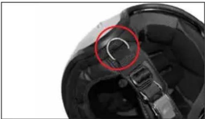
Some versions of this helmet feature a metallic ring called HELMET LOCK RING (Fig. 17), that can be used for hanging the helmet to the special hook placed on many motorbikes.
WARNING
- Only use the HELMET LOCK RING to hang the helmet to the motorbike.
- Check that - when hung to the hook- the helmet is not directly exposed to heat sources or other stresses that may modify its characteristics or damage it.
- the HELMET LOCK RING is not related to the helmet retention system (strap) and/or its adjustment (see specific instructions).
- Never use the HELMET LOCK RING to fasten the helmet to the head and/or to adjust the tension (see instructions above).
- Do not remove the HELMET LOCK RING form the retention system strap.
- In case of malfunctioning or damages, please contact an authorised Nolan dealer.
natural_image
Line drawing of a person in profile wearing a helmet, with red arrows indicating direction (no text or symbols)
natural_image
Illustration of a hand holding a tool, with red arrows indicating direction (no text or symbols)
text_image
Prohibition sign with red X symbol crossed over a heart-shaped figure, indicating exclusion or prohibition of a device.GEBRAUCHSANLEITUNG
VISIER
natural_image
Line drawing of a person in profile view with red arrows indicating direction (no text or symbols)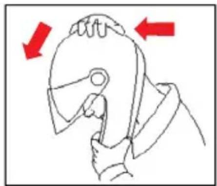
natural_image
Line drawing of a person using a tool to press or adjust a piece of material, with red arrows indicating direction (no text or symbols)
text_image
Prohibition sign with red X symbol crossed over hands, indicating no intervention or absence of interventionINSTRUCTIONS D'UTILISATION
ÉCRAN
natural_image
Line drawing of a person wearing a helmet with red arrows indicating direction (no text or symbols)
natural_image
Line drawing of a hand gripping a hard disk, with red arrows indicating direction (no text or symbols)
text_image
Prohibition sign with red X symbol crossed over a diagram showing hands holding a tool, possibly indicating a medical or diagnostic procedure.INSTRUCCIONES DE USO
PANTALLA
natural_image
Line drawing of a person in a helmet with red arrows indicating direction (no text or symbols)
natural_image
Line drawing of a person using a tool to hold an object, with red arrows indicating direction (no text or symbols)
text_image
Diagram showing two hands holding a balloon with a red 'X' symbol crossed out, indicating prohibition or exclusion.INSTRUÇÕES DE USO
VISEIRA
1. Desmontar a Viseira
natural_image
Line drawing of a human head in profile with red arrows indicating direction (no text or symbols)
natural_image
Line drawing of a hand holding a tool, with red arrows indicating direction (no text or symbols)
text_image
Prohibition sign with red X symbol crossed over a human figure holding an object, indicating no intervention or prohibition.GEBRUIKSAANWIJZING
VIZIER
natural_image
Line drawing of a person wearing a helmet and holding a tool, with red arrows indicating direction (no text or symbols)
natural_image
Line drawing of a hand holding a tool, with red arrows indicating direction (no text or symbols)
text_image
Diagram showing two people crossed out with a red 'X' symbol, indicating prohibition or exclusion of a device.BRUGERVEJLEDNING
VISIR
1. Afmontering
natural_image
Line drawing of a person in a helmet with red arrows indicating direction (no text or symbols)
natural_image
Line drawing of a person using a tool to grip a piece, with red arrows indicating direction (no text or symbols)
text_image
Diagram showing two hands crossed out of a device with a red prohibition symbol, indicating no protection or exclusion.ΟΔΗΓΙΕΣ ΧΡΗΣΗΣ
ZEΛATINA
natural_image
Close-up of a silver sports helmet with a red arrow pointing to the nose area (no text or symbols visible)Fig. 1
natural_image
Close-up of a silver sports helmet with a red arrow pointing to the center bull hole (no text or symbols visible)Fig. 2
natural_image
Close-up of a hand adjusting a helmet component with a red arrow pointing to the lock (no visible text or symbols)Fig. 3 Fig. 4
natural_image
Close-up of a hand inserting a small component into a metallic cylindrical device (no text or symbols visible)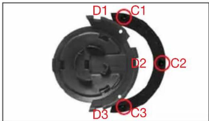
text_image
D1 C1 D2 C2 D3 C3Fig. 6
text_image
B1 A1Fig. 5
natural_image
Close-up of a silver sports helmet with a red arrow pointing to the front gear (no text or symbols visible)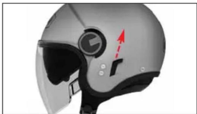
natural_image
Close-up of a silver sports helmet with a blue circular emblem and red arrow indicator (no text or symbols)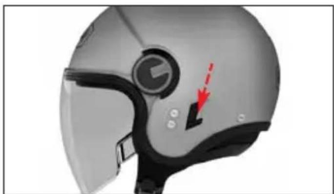
natural_image
Close-up of a gray motorcyclist helmet with visible visor and red arrow indicator (no text or symbols)Fig. 7 A Fig. 7 B
natural_image
Close-up of a helmet with visible red arrow pointing to the side panel (no text or symbols)Fig. 8
natural_image
Illustration of a pair of safety goggles with a red arrow pointing to the lower right (no text or symbols present)Fig. 9
natural_image
Diagram of a pair of eyeglasses with red arrows pointing to the curve and lines (no text or symbols)Fig. 10 Fig. 11
natural_image
Diagram showing a curved object with red arrows pointing downward, possibly indicating force or movement (no text or symbols present)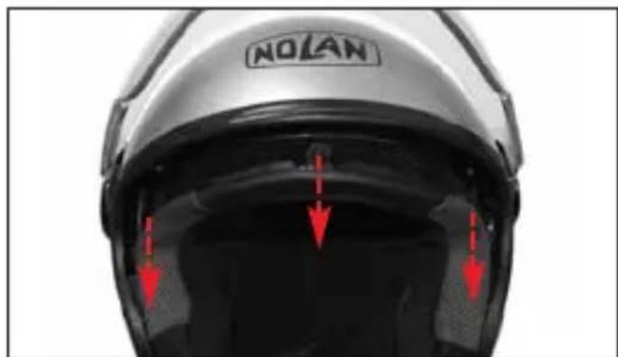
text_image
NOLANFig. 13
natural_image
Close-up of a black cable with a red circle highlighting a cable extension (no text or symbols visible)Fig. 12
natural_image
Close-up of a car head with red arrows pointing to the inner body area (no text or symbols visible)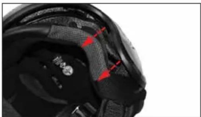
natural_image
Close-up of a black athletic helmet with red arrows pointing to specific areas (no text or symbols visible)Fig. 14 Fig. 15
natural_image
Interior view of a helmet with visible gear and a red arrow pointing to a component (no text or symbols)Fig. 16 A
natural_image
Close-up of a black and silver athletic shoe with visible grip and red arrow indicating a specific part (no text or symbols)Fig. 16 B
natural_image
Close-up of a car's head and torso with a red circle highlighting the curved arm area (no text or symbols present)Fig. 17
- Questo casco è prodotto in uno stabilimento che rispetta l'ambiente. Al termine del suo utilizzo, si raccomanda di effettuarne lo smaltimento, seguendo le specifiche normative di legge vigenti nel luogo o Paese di residenza.
- This helmet is manufactured in a plant respecting the environment. At the end of its use, it is recommended to dispose of it according to specific regulations in force over the place or Country of residence.
- Dieser Helm wurde mit größtmöglicher Rücksicht auf die Umwelt hergestellt. Nach Gebrauch entsorgen Sie ihn bitte entsprechend den landes- oder ortsüblichen Bestimmungen.
- Ce casque est fabriqué dans un établissement qui respecte l'environnement. À la fin de son utilisation, il est recommandé de procéder à son élimination, suivant les règles spécifiques en vigueur dans le lieu ou le pays de résidence.
- Este casco ha sido fabricado en una instalación industrial que respeta el medio ambiente. Una vez cumplido su servicio, para eliminarlo, se recomienda acudir a un centro de recogida selectiva y actuar según las normas vigentes en el lugar y país de residencia.
- Este capacete é produzido numa fábrica que respeita o ambiente. No final da sua utilização, recomenda-se que seja eliminado de acordo com regulamentação específica em vigor no local ou País de residência.
- Deze helm wordt op een milieu vriendelijke manier vervaardigd. Wanneer de helm niet meer gebruikt wordt dient u deze helm af te voeren volgens de geldende milieu eisen.
- Denne hjelm er lavet med respekt for miljøet. Når den engang skal bortskaffes, bør det være i overensstemmelse med miljøreglerne.
• Το κρανος αυτο εχει κατασκευαστει σε εργοστασιο που σεβεται το περιβαλλον Μετα το περας της χρησης του συνισταται να το καταστρεψετε συμφωνα με τους κανονισμους που ισχυουν στο τοπο ή χωρα διαμονης σας