
Quadrum Green 310 S - Laser level Laserliner - Free user manual and instructions
Find the device manual for free Quadrum Green 310 S Laserliner in PDF.
| Product type | Fully automatic rotary laser level |
| Brand | Laserliner |
| Model | Quadrum Green 310 S |
| Dimensions (L x H x W) | 215 x 205 x 165 mm |
| Weight (with battery) | 2.6 kg |
| Main power supply | High-performance rechargeable battery or 4 type C batteries |
| Charging time of battery | approx. 6 hours |
| Battery life (red/green) | approx. 35 h / 14 h |
| Battery life (batteries red/green) | approx. 50 h / 8 h |
| Accuracy | ± 1 mm / 10 m |
| Self-leveling range | ± 5° |
| Rotation speeds | 0, 60, 120, 300, 600 rpm |
| Main laser | Green 532 nm / Red 635 nm |
| Laser class | 3R (EN60825-1:2007-10), < 5 mW |
| Additional plumb laser | Red, integrated |
| Range of laser receiver (optional) | Up to 300 m (SensoLite 310) |
| Protection rating | IP 66 (dust and rain) |
| Operating temperature green/red | 0°C to +40°C / -10°C to +50°C |
| Storage temperature | -10°C to +70°C |
| Remote control | Infrared, range up to 30 m, AAA batteries |
| Main functions | Self-leveling, point/scan/rotation/receiver modes, manual tilt up to 5°, anti-drift system (ADS) |
| Calibration | Check regularly before each use and after transport |
| Cleaning | Soft, dry cloth |
| Safety instructions | Laser class 3R – do not look directly into the beam, keep out of reach of children |
Frequently Asked Questions - Quadrum Green 310 S Laserliner
User questions about Quadrum Green 310 S Laserliner
0 question about this device. Answer the ones you know or ask your own.
Ask a new question about this device
Download the instructions for your Laser level in PDF format for free! Find your manual Quadrum Green 310 S - Laserliner and take your electronic device back in hand. On this page are published all the documents necessary for the use of your device. Quadrum Green 310 S by Laserliner.
USER MANUAL Quadrum Green 310 S Laserliner
Please read the operating instructions as well as the enclosed brochures "Guarantee and additional notices" and "Laser class 3R safety instructions". Follow the instructions they contain. Safely keep these documents for future reference.
Fully automatic rotary laser with red or green laser technology.
- With additional red plumb laser
- Laser modes: spot, scan, rotary and hand receiver mode
- All functions can be controlled remotely.
- optional SensoLite 310: Laser receiver range up to 300 m radius
- optional SensoMaster 400 (Quadrum red only): Laser receiver range in excess of 300m radius. With longer laser receiver unit and millimetre exact distance reading for laser level.
General safety instructions
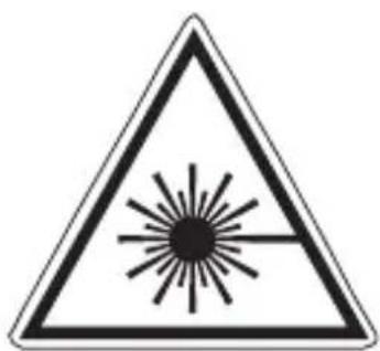
Laser radiation!
Avoid direct exposure to the eyes.
Laser class 3R
< 5 mW · 530 - 670 nm
EN60825-1:2007-10
Caution: Prior to using the laser, you must read the safety instructions for laser class 3R thoroughly. Warning signs must not be removed from the laser measuring device! Do not look directly into the beam. Lasers must be kept out of reach of children. Never intentionally aim the device at people. This is a quality laser measuring device and is 100% factory adjusted within the stated tolerance. For reasons of product liability, we must also draw your attention to the following: Regularly check the calibration before use, after transport and after extended periods of storage. We also wish to point out that absolute calibration is only possible in a specialist workshop. Calibration by yourself is only approximate and the accuracy of the calibration will depend on the care with which you proceed.
Special product features and functions

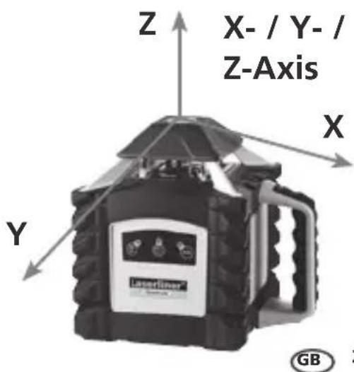
The rotary laser aligns itself automatically. It is set to the initial position (to within an operating angle of ± 5^ ) and the system then performs the necessary fine adjustment, with three measurement sensors detecting the X, Y and Z axes.

The anti-drift system (ADS) prevents erroneous or inaccurate measurements. How it works: continuous monitoring of the alignment of the laser is activated 30 seconds after the ADS is switched on. If the device moves due to the influence of external factors or the laser loses its height reference, the laser will come to a standstill. Additionally, the laser flashes and the tilt LED is lit continuously. To continue working, press the tilt button again or switch the device off then on again. Erroneous and inaccurate measurements are thus prevented simply and reliably.
The ADS is not active following switch-on. Once the device has been set up, press the tilt button to activate the ADS, enabling you to protect the laser from changes in position caused by the device being disturbed by external factors. The tilt LED flashes to indicate that the ADS function is active; see the diagram below.

The ADS does not activate the monitoring function until 30 seconds after the laser levelling procedure has been completed (set-up phase). The tilt LED flashes every second during the set-up phase, rapid flashing, when ADS is active.
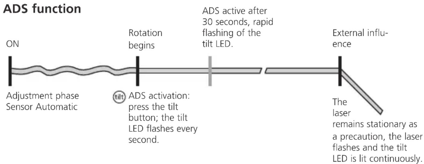
ADS function

lock
Transport LOCK: The device is protected by a special motor
brake during transport.

The device characterised by specific protection against
dustand rain.
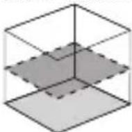
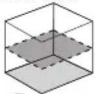
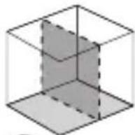
Space grids: These show the laser planes and functions.
auto: Automatic alignment / man: Manual alignment
auto auto man
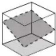
Horizontal levelling
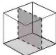
Vertical levelling
Slope function
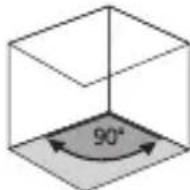
90^ angle
90^ reference function
Quadrum Green: green laser technology
The distance at which a laser is visible to the naked eye depends on its colour i.e. wavelength. This is because of the human eye's physiology - green appears brighter to us than red. Depending on ambient light, green lasers are therefore many times more visible than red lasers; in indoor areas this is as much as 12 times brighter. This permits applications on dark surfaces, over longer distances and work in very bright ambient light. A red laser with a 635 nm wavelength is used as a reference value for brightness differentiation.
In contrast to red lasers, green laser light can only be produced indirectly. This is a source of potential characteristic fluctuations:
- The optimal operating temperature is 20^ . Outside its operating temperature range of 0 - 40^ Quadrum Green is darker. IMPORTANT: Allow the unit enough time to adapt to the ambient temperature before switching the unit on.
- Laser brightness may vary somewhat from one unit to another. This is a natural phenomena and excluded from warranty claims.
- Green Laser will only work with certain Receivers. The maximum range of the Receiver is shorter, please refer to technical details.
Battery charging
- Charge the device's battery completely prior to use.
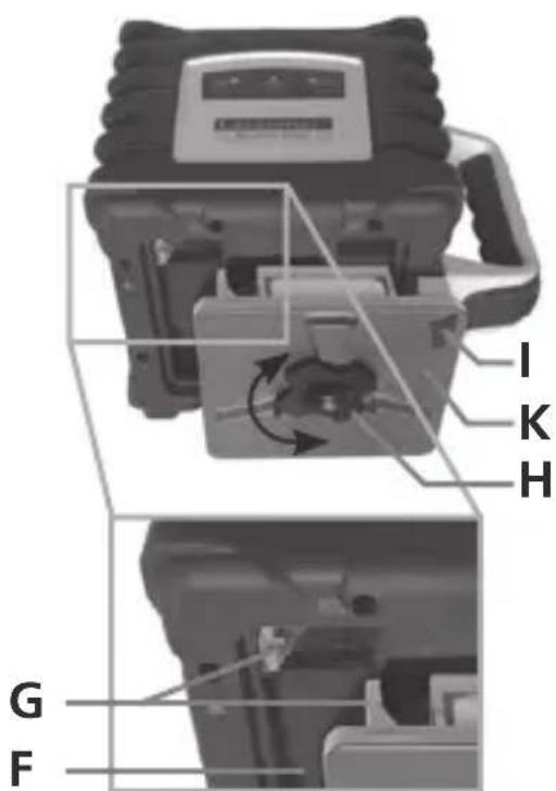
- Connect the charger to mains power supply and the charging socket (I) of the battery compartment (K). Please only use the charger supplied; using a different charger will invalidate the warranty. The rechargeable battery can also be charged when it is not inserted in the device.
- When the rechargeable battery is being charged, the LED on the charger (M) lights up red. When the LED changes to green, charging is complete. When the unit is not connected to the charger the power charger's LED lamp will blink.
Alkaline batteries (4 x type C) can be used as an alternative. Insert them in the battery compartment (J) as per the installation symbols. - Insert battery (K) / battery compartment (J) into slot (F) and secure it in place with fastening screw (H). The electrical contacts (G) must be connected.
- With the rechargeable battery inserted, the device is ready to run even during charging.
- When all 3 LEDs (2, 4, 5) light up briefly and the device switches off, the batteries must be replaced or the rechargeable battery charged.
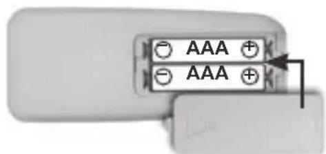
Insert batteries into the remote control
- Observing the correct polarity.
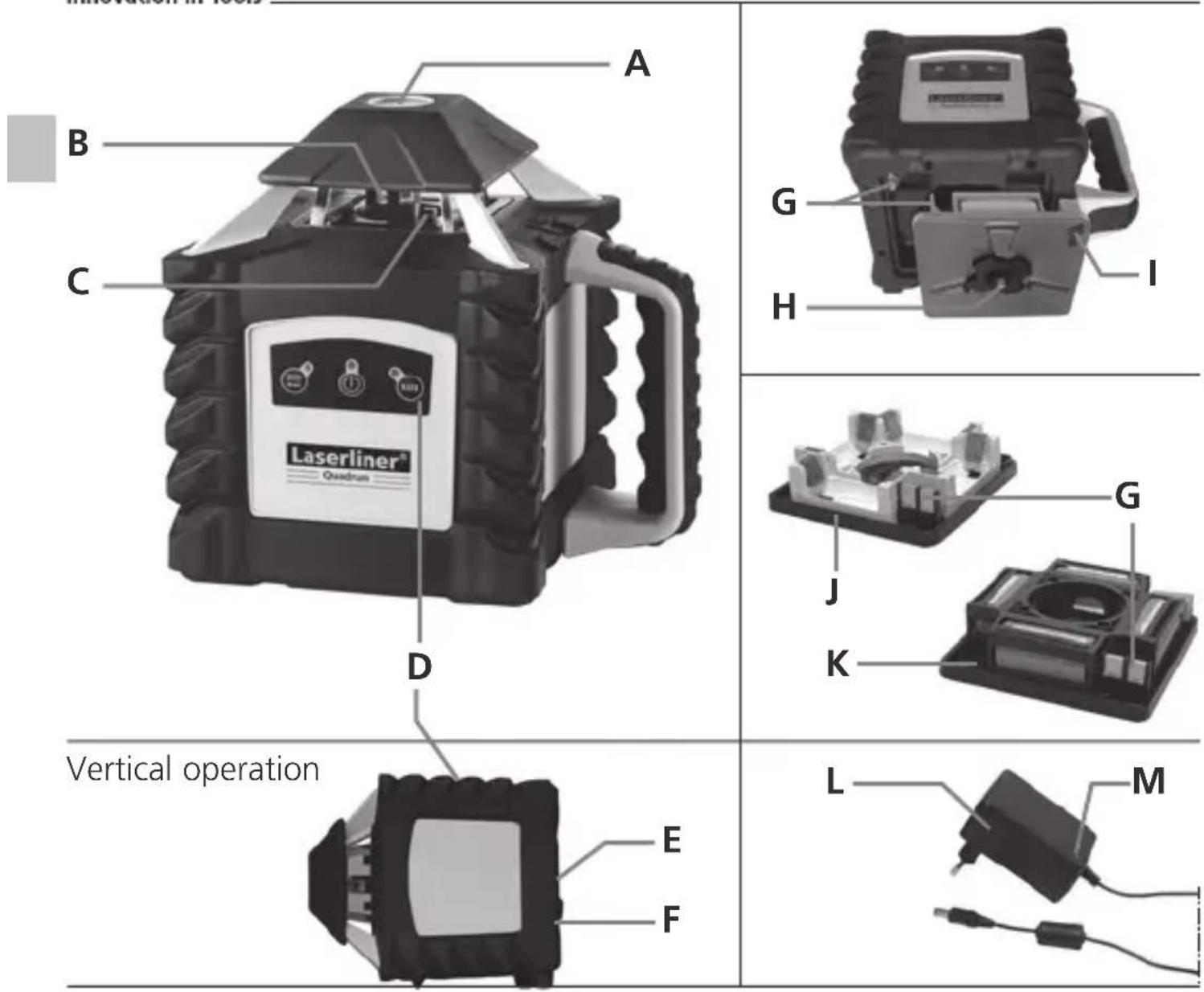
A Reference / plumb laser outlet
B Prism head / laser beam outlet
C Receiver diodes for remote control (4 x)
D Control panel
E 5/8" thread / Reference, plumb laser outlet
F Slot for rechargeable battery / battery compartment
G Electrical contacts
H Battery compartment / battery fastening nut
Charging socket
Battery compartment
K Rechargeable battery compartment
L Mains unit / charger
M Operation indicator red: battery is charging green: charging process complete
6
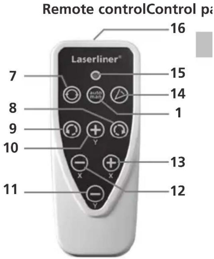
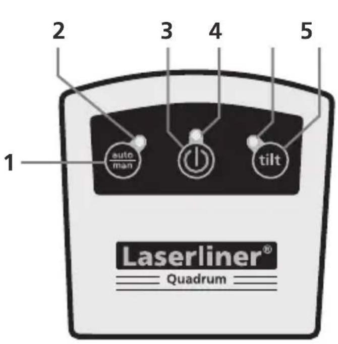
1 auto/man function
2 auto/man function LED LED off: automatic alignment LED on: manual alignment
3 ON/OFF button
4 Operation indicator
5 Tilt function LED
6 Tilt function
7 Rotary speed for selection, 600 / 300 / 120 / 60 / 0 rpm
8 Positioning button (rotate to the right)
9 Positioning button (rotate to the left)
10 auto/man. function: Y axis proceed as above
11 auto/man. function: Y axis proceed as below
12 auto/man. function: X axis proceed as above
13 auto/man. function: X axis proceed as below
14 Scan mode
15 Operation indicator
16 Infrared signal emitter
Horizontal levelling and vertical levelling
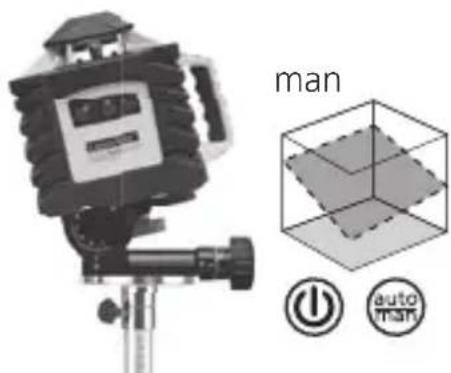
Horizontal: Position the device on a level surface or on a tripod.
- Vertical: Set the unit on its side feet. The operator panel should be at the top. With the optional wall bracket (product ref. 080.70), the device can be mounted on a tripod for vertical usage.
- Press the "ON/OFF" switch
auto auto
①
①

auto/man function LED OFF: Automatic alignment
- The device levels itself automatically to within a range of ± 5^ . During the set-up phase, the laser flashes and the prism head remains stationary. When levelling is complete, the laser lights up continuously and rotates at maximum speed. Refer also to the sections about "Sensor Automatic" and "ADS Tilt".

If the device has been placed on a surface with too much of a slope (more than 5^ ), there is a warning sound, the prism head remains stationary and the laser starts to flash. The device must then be placed on a more even surface.
Positioning the vertical laser level
In vertical mode the laser level can be positioned exactly. "Sensor Automatic" remains active and levels to the vertical laser level. Refer to the illustration below.

If the auto/man LED flashes, the maximum adjustment range of 5^ has been reached. Set up the device horizontally, turn it off and then on again.
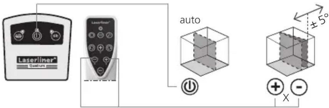
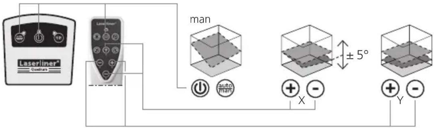
Slope function up to 5^ - horizontal
This function deactivates the automatic sensor. To use the function, press the auto/man button. The plus/minus buttons are used to re-adjust the slope by means of a motor. In the process the X-and Y-axis can be adjust separately. Refer to the illustrations below.
Slope function up to 5^ - vertical
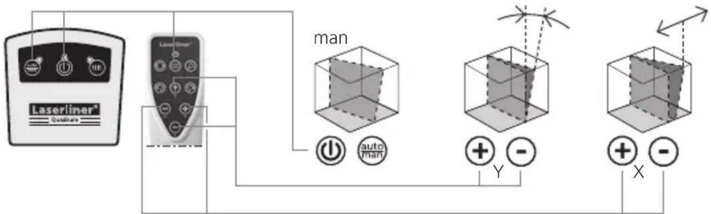

When the 5^ maximum slope range has been reached, the laser will stay fixed and blink. In this case, reduce the slope angle.
Slope function > 5^
Steeper slopes can be set using the angle plate, which is available as an optional extra (product ref. 080.75). TIP: Allow the device to align itself automatically and set the angle plate to the zero position. Then press the auto/man button to switch the automatic sensor off. Finally, incline the device to the angle you require.

auto/man function LED ON: Manual alignment
Laser modes
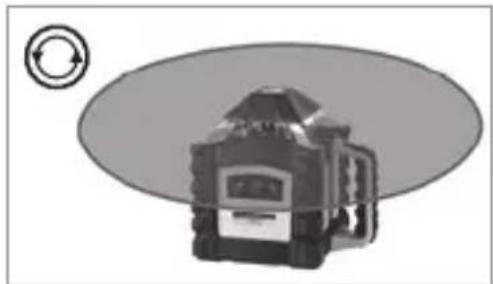
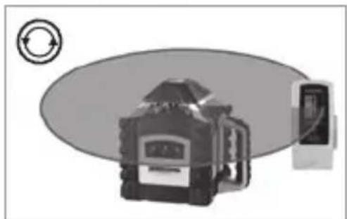
Rotary mode
The following speeds can be set using the rotary button: 0, 60, 120, 300, 600 rpm
Spot mode
You access spot mode by pressing the rotary button repeatedly until the laser stops rotating. The laser can then be positioned exactly at the measuring point by means of the direction buttons.
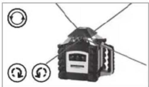
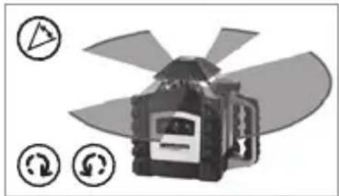
Scan mode
The scan button can be used to activate and set a lightintensive segment in 4 different widths. You position the segment via the direction buttons.
Hand receiver mode
Working with the laser receiver (available as an optional extra): Set the rotary laser to maximum speed and switch on the laser receiver. Refer to the operating instructions for the respective laser receiver about this.
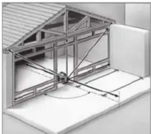
Working with the reference/plumb laser
The unit has two reference lasers. In horizontal operation these lasers can be used to drop a perpendicular. In vertical operation these reference lasers are used to align the unit. This is done by adjusting the reference lasers parallel to the wall. This aligns the vertical laser plane at a right angle to the wall, see illustration.
| Technical data (Subject to technical alterations) | |
| Self-levelling range ± 5° | |
| Accuracy ± 1 mm / 10 m | |
| Horizontal / vertical levelling | Automatic with electronic sensors and servo motors |
| Self-levelling alignment time | Approx. 30 seconds over the entire operating angle |
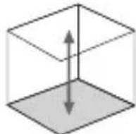
| Vertical reference beams 90° to rotation plane | |
| Rotation speed 0, 60, 120, 300, 600 RPM | |
| Remote control Infrared IR | |
| Laser wavelengths green / red 635 nm / 532 nm | |
| Laser class red / green 3R (EN60825-1:2007-10) | |
| Laser output rating red / green < 5 mW | |
| Power supply | High-performance rechargeable battery /batteries (4 x type C) |
| Rechargeable battery life red / green | approx. 35 h / approx. 14 h |
| Non-rechargeable battery life red / green | approx. 50 h / approx. 8 h |
| Battery recharging time ca. 6 h | |
| Operating temperature red / green -10°C | ... + 50°C / 0°C ... + 40°C |
| Storage temperature -10°C ... + 70°C | |
| Protection class IP 66 | |
| Dimensions (W x H x D) / Weight (incl. batteries) | 215 x 205 x 165 mm / 2,6 kg |
| Remote control | |
| Power supply 2 x type AAA | |
| Remote control range max. 30 m (IR-Control) | |
| Weight (incl. battery) | 0,07 kg |
EU directives and disposal
This device complies with all necessary standards for the free movement of goods within the EU.
This product is an electric device and must be collected separately for disposal according to the European Directive on waste electrical and electronic equipment.
Further safety and supplementary notices at:
www.laserliner.com/info

Preparing the calibration check
It is possible for you to check the calibration of the laser. To do this, position the device midway between 2 walls, which must be at least 5 metres apart. Switch the device on. The best calibration results are achieved if the device is mounted on a tripod. IMPORTANT: The automatic sensor must be active (auto/man. LED is off).
- Mark point A1 on the wall.
- Turn the device through 180^ and mark point A2. You now have a horizontal reference between points A1 and A2.
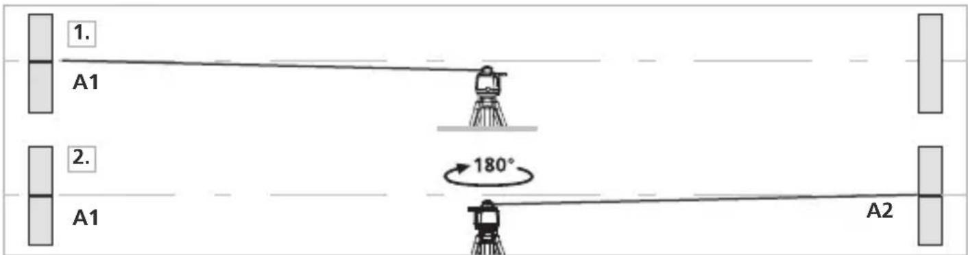
Performing the calibration check
- Position the device as near as possible to the wall at the height of point A1. Now adjust the device in the X axis.
- Turn the device through 180^ and mark point A3. The difference between points A2 and A3 is the tolerance for the X axis.
- To check the Y and Z axis, repeat steps 3 and 4.
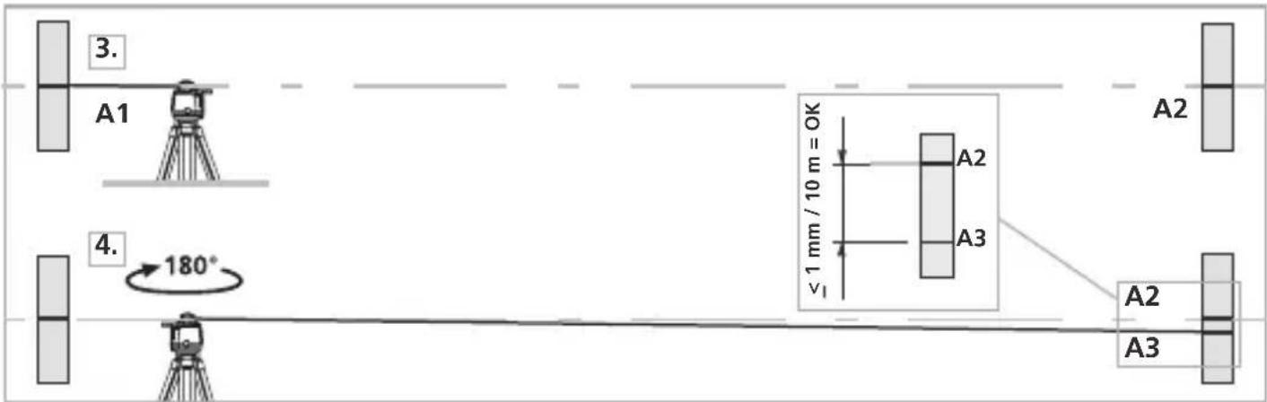

If points A2 and A3 are more than 1mm / 10m apart on either the X or Y axis, the device is in need of adjustment. Contact your authorised dealer or else the UMAREX-LASERLINER Service Department.
Adjustment mode
Take the alignment of the rotary laser into account when performing adjustment work. Always adjust all the axes.
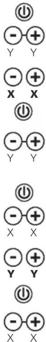
X axis adjustment
Activate adjustment mode: Switch on the Quadrum. Press the Y axis plus/minus buttons simultaneously until the auto/man. LED flashes.
Adjustment: Use the X axis plus/minus buttons to move the laser from its current position to the height of reference point A2.
Cancel adjustment: Switch the device off.
Save: Press the Y axis plus/minus buttons simultaneously until the auto/man. LED goes off.
Adjust the Y and Z axes
Activate adjustment mode: Switch on the Quadrum. Press the X axis plus/minus buttons simultaneously until the tilt LED flashes.
Adjustment: Use the Y axis plus/minus buttons to move the laser from its current position to the height of reference point A2.
Cancel adjustment: Switch the device off.
Save: Press the X axis plus/minus buttons simultaneously until the tilt LED goes off.
To adjust the Z axis, set up the device vertically and proceed in the same manner as for the Y axis adjustment.
!
Regularly check the adjustment before use, after transport and after extended periods of storage. Always make sure to control all axes.
!
Quadrum / Quadrum Green
SERVICE

Umarex GmbH & Co KG
-Laserliner
- Fully automatic rotary laser with red or green laser technology.
- General safety instructions
- Special product features and functions
- Quadrum Green: green laser technology
- Battery charging
- Insert batteries into the remote control
- Horizontal levelling and vertical levelling
- Positioning the vertical laser level
- Slope function up to 5° - horizontal
- Slope function up to 5° - vertical
- Slope function > 5^ °
- Laser modes
- Rotary mode
- Spot mode
- Scan mode
- Hand receiver mode
- Working with the reference/plumb laser
- EU directives and disposal
- Preparing the calibration check
- Performing the calibration check
- Adjustment mode
- X axis adjustment
- Adjust the Y and Z axes
- Quadrum / Quadrum Green
- Umarex GmbH & Co KG
Brand : Laserliner
Model : Quadrum Green 310 S
Category : Laser level