 — Laser level — Mode d'emploi PDF")
PLL 2 (Set) - Laser level BOSCH - Free user manual and instructions
Find the device manual for free PLL 2 (Set) BOSCH in PDF.
| Product type | Cross-line laser level (Cross-line laser PLL 2) |
| Brand | Bosch |
| Model | PLL 2 (Set) |
| Dimensions (L × W × H) | 123 × 67 × 110 mm |
| Weight | 0.4 kg (according to EPTA 01/2003) |
| Power supply | 3 LR03 (AAA) 1.5 V batteries |
| Battery life | Approx. 5 hours |
| Laser class | 2 (IEC 60825-1:2007-03) |
| Laser type | 640 nm, <1 mW |
| Working range | Up to approx. 10 m |
| Self-leveling range | ±4° |
| Leveling time | <5 s |
| Leveling accuracy | ±0.5 mm/m |
| Inclination measurement range | 0 – 90° |
| Digital measurement accuracy (spirit level) | ±0.2° (after calibration at 0° and 90°) |
| Measurement accuracy with laser lines | ±1.2° |
| Operating temperature | +10 °C to +40 °C |
| Storage temperature | -20 °C to +70 °C |
| Max. relative humidity | 90 % |
| Tripod thread | 1/4" |
| Operating modes | Self-leveling (cross lines/horizontal/vertical), inclination function with angle display, digital spirit level |
| Calibration | Calibratable inclination sensor via Cal button (with 180° rotation) |
| Maintenance and cleaning | Clean with a soft, damp cloth; do not use solvents; store in the protective case |
| Safety | Do not look into the laser beam; do not point at people; laser class 2; keep out of reach of children |
| Spare parts and repairability | Use only original Bosch spare parts; repair by qualified personnel |
| General information | Supplied with protective case, laser viewing glasses, tripod (depending on version); automatic switch-off after 30 min |
Frequently Asked Questions - PLL 2 (Set) BOSCH
User questions about PLL 2 (Set) BOSCH
0 question about this device. Answer the ones you know or ask your own.
Ask a new question about this device
Download the instructions for your Laser level in PDF format for free! Find your manual PLL 2 (Set) - BOSCH and take your electronic device back in hand. On this page are published all the documents necessary for the use of your device. PLL 2 (Set) by BOSCH.
USER MANUAL PLL 2 (Set) BOSCH
OBJ DOKU-36397-003.fm Page 1 Thursday, January 23, 2014 10:24 AM
Robert Bosch GmbH
Power Tools Division
70745 Leinfelden-Echterdingen
Germany
www.bosch-pt.com
1618 C00 93G (2014.02) 0/168 WEU

WEUWEU

natural_image
Illustration of a Bosch electric scooter (no text or symbols visible)PLL 2

BOSCH
OBJ_BUCH-2030-003.book Page 4 Thursday, January 23, 2014 10:38 AM


4


natural_image
Interior view of a room with a camera on a tripod, two blank walls, and a label 'B' in the top-left corner (no readable text or symbols)
1 618 C00 93G | (23.1.14) Bosch Power Tools


OBJ_BUCH-2030-003.book Page 5 Thursday, January 23, 2014 10:38 AM


natural_image
Illustration of a camera setup with a beam splitter and two parallel plates, no text or symbols present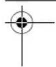


Bosch Power Tools 1 618 C00 93G | (23.1.14)


OBJ_BUCH-2030-003.book Page 6 Thursday, January 23, 2014 10:38 AM


6|


1 618 C00 93G | (23.1.14) Bosch Power Tools


OBJ_BUCH-2030-003.book Page 7 Thursday, January 23, 2014 10:38 AM


Bosch Power Tools 1 618 C00 93G | (23.1.14)


8 | Deutsch
Deutsch
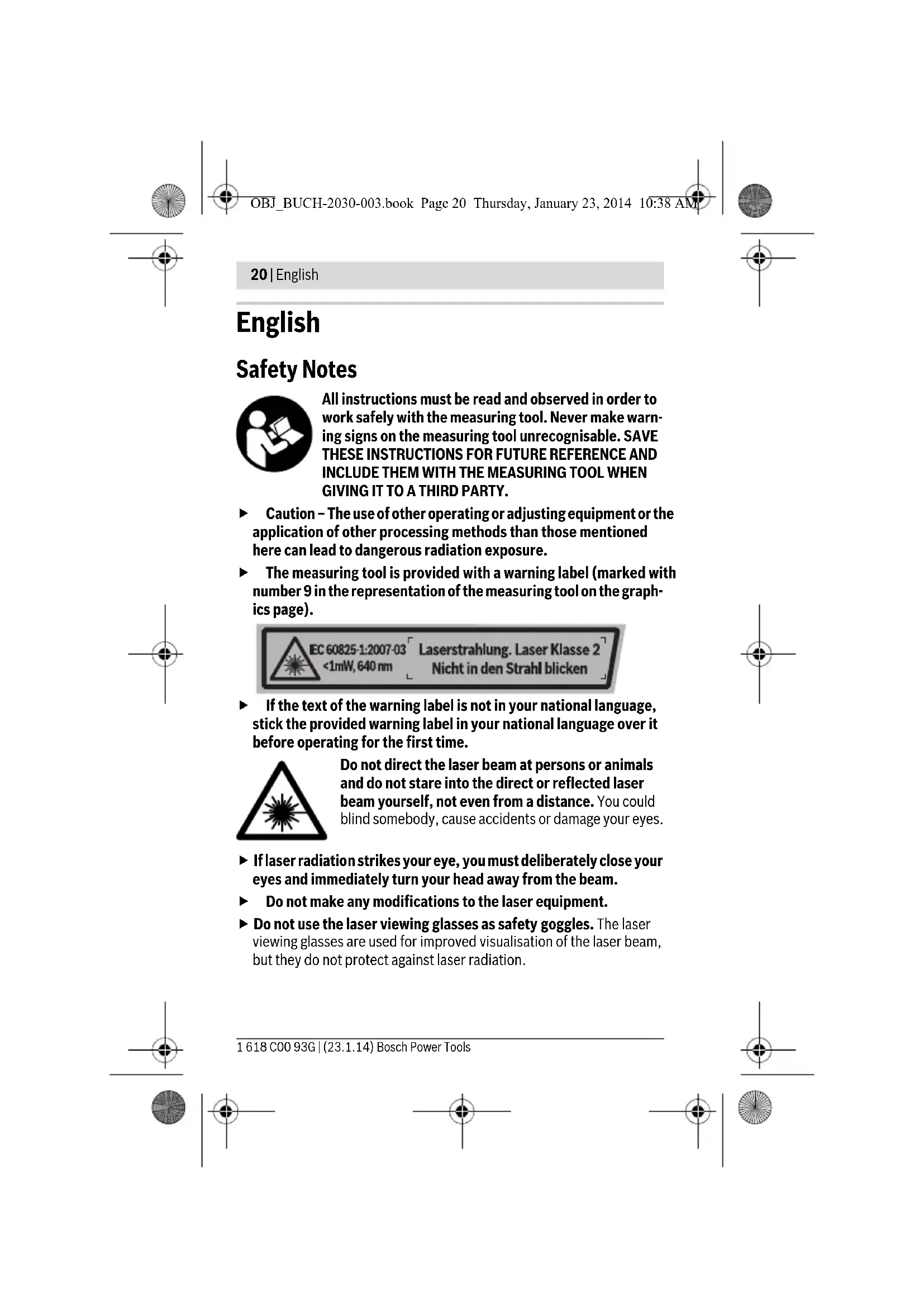
Sicherheitshinweise

All instructions must be read and observed in order to work safely with the measuring tool. Never make warning signs on the measuring tool unrecognisable. SAVE THESE INSTRUCTIONS FOR FUTURE REFERENCE AND INCLUDE THEM WITH THE MEASURING TOOL WHEN GIVING IT TO A THIRD PARTY.
- Caution – The use of other operating or adjusting equipment or the application of other processing methods than those mentioned here can lead to dangerous radiation exposure.
The measuring tool is provided with a warning label (marked with number 9 in the representation of the measuring tool on the graphics page).

▶ If the text of the warning label is not in your national language, stick the provided warning label in your national language over it before operating for the first time.
Do not direct the laser beam at persons or animals and do not stare into the direct or reflected laser beam yourself, not even from a distance. You could blind somebody, cause accidents or damage your eyes.
▶ If laser radiation strikes your eye, you must deliberately close your eyes and immediately turn your head away from the beam.
▶ Do not make any modifications to the laser equipment.
▶ Do not use the laser viewing glasses as safety goggles. The laser viewing glasses are used for improved visualisation of the laser beam, but they do not protect against laser radiation.
1 618 C00 93G | (23.1.14) Bosch Power Tools


English | 21
▶ Do not use the laser viewing glasses as sun glasses or in traffic. The laser viewing glasses do not afford complete UV protection and reduce colour perception.
▶ Have the measuring tool repaired only through qualified specialists using original spare parts. This ensures that the safety of the measuring tool is maintained.
▶ Do not allow children to use the laser measuring tool without supervision. They could unintentionally blind other persons or themselves.
▶ Do not operate the measuring tool in explosive environments, such as in the presence of flammable liquids, gases or dusts.
Sparks can be created in the measuring tool which may ignite the dust or fumes.


Keep the measuring tool away from cardiac pacemakers. The magnet inside the measuring tool generates a field that can impair the function of cardiac pacemakers.
- Keep the measuring tool away from magnetic data media and magnetically-sensitive equipment. The effect of the magnet can lead to irreversible data loss.

Product Description and Specifications
Intended Use
The measuring tool is intended to determine and check horizontal and vertical lines as well as lines at a defined angle. Moreover, the measuring tool is intended to determine the angles of objects.
The measuring tool is suitable exclusively for operation in enclosed working sites.
The measuring tool is not intended for commercial use.
Bosch Power Tools 1 618 C00 93G | (23.1.14)


22 | English
Product Features
The numbering of the product features shown refers to the illustration of the measuring tool on the graphic page.
1 Laser line
2 Mode button
3 C a l calibration button
4 Display
5 On/Off switch

On Automatic levelling on

On Tilt function with angle indicator on
Off Measuring tool off
6 Tripod mount 1/4"
7 Battery lid
8 Latch of battery lid
9 Laser warning label
10 Serial number
11 Laser target plate
12 Tripod*
13 Protective pouch
14 Laser viewing glasses*
* The accessories illustrated or described are not included as standard delivery.
Display Elements
a Tilt measurement on (automatic levelling off)
b Digital spirit level on
c Automatic levelling on
d Tilt angle symbol
e Battery low indicator
f Calibration completed
g Measuring range warning
h Tilt angle
1 618 C00 93G | (23.1.14) Bosch Power Tools


English | 23
Technical Data
| Cross-line Laser PLL 2 | |
| Article number | 3 603 F53 4.. |
| Working range to approx. | 10 m |
| Measuring range | 0 - 90° |
| Levelling Accuracy | ±0.5 mm/m |
| Measuring Accuracy | |
| - digital (spirit level) | ±0.2 ^a) B) |
| - with laser lines | ±1.2° |
| Self-levelling range, typically | ±4° |
| Levelling duration, typically | < 5 s |
| Automatic Levelling | ● |
| Horizontal mode/vertical mode | ● |
| Cross-line mode | ● |
| Tilt function with angle indicator | ● |
| Digital vial | ● |
| Operating temperature | +10 °C...+40 °C |
| Storage temperature | -20 °C...+70 °C |
| Relative air humidity, max. | 90% |
| Laser class | 2 |
| Laser type | 640 nm, <1 mW |
| C_6 (laser line) 1 | |
| Tripod mount | 1/4" |
| Batteries | 3 x 1.5 V LR03 (AAA) |
| Operating life time, approx. | 5 h |
| Weight according to EPTA-Procedure | |
| 01/2003 | 0.4 kg |
| Dimensions (length x width x height) | 123 x 67 x 110 mm |
| A) After calibration at 0° and 90° at an additional pitch error of max. ±0.02°/degree up to 90°. | |
| B) over 25 °C gradual deterioration | |
| The measuring tool can be clearly identified with the serial number 10 on the type plate. | |
Bosch Power Tools 1 618 C00 93G | (23.1.14)
24 | English
Assembly
Inserting/Replacing the Batteries
Alkali-manganese batteries are recommended for the measuring tool.
To open the battery lid 7, press on the latch 8 and fold the battery lid up. Insert the batteries. When inserting, pay attention to the correct polarity according to the representation on the inside of the battery lid.
Always replace all batteries at the same time. Only use batteries from one brand and with the identical capacity.
▶ Remove the batteries from the measuring tool when not using it for extended periods. When storing for extended periods, the batteries can corrode and self-discharge.
Operation
Initial Operation
▶ Protect the measuring tool against moisture and direct sun light.
▶ Do not subject the measuring tool to extreme temperatures or variations in temperature. As an example, do not leave it in vehicles for longer periods. In case of large variations in temperature, allow the measuring tool to adjust to the ambient temperature before putting it into operation.
- Avoid heavy impact to or falling down of the measuring tool. Damage to the measuring tool can impair its accuracy. After heavy impact or shock, compare the laser lines with a known horizontal or vertical reference line.
▶ Switch the measuring tool off during transport. When switching off, the levelling unit, which can be damaged in case of intense movement, is locked.
Switching On and Off
To switch on the measuring tool, slide the On/Off switch 5 to one of the "On" positions (Off On On
▶ Do not point the laser beam at persons or animals and do not look into the laser beam yourself, not even from a large distance.
To switch off the measuring tool, slide the On/Off switch 5 to the "Off" position. When switching off, the levelling unit is locked.


English | 25
▶ Do not leave the switched on measuring tool unattended and switch the measuring tool off after use. Other persons could be blinded by the laser beam.
To save energy, only switch the measuring tool on when you are using it.
Operation Modes (see figures A - D)
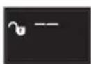
Once the measuring tool has been switched on, it is in the automatic levelling operation mode 📋 or in the tilt function with angle indicator operation mode 🔒
To change the mode, repeatedly press the "Mode" button 2 until the desired mode appears on the display.
The following operation modes are available:
Automatic levelling operation mode:
Indication Mode

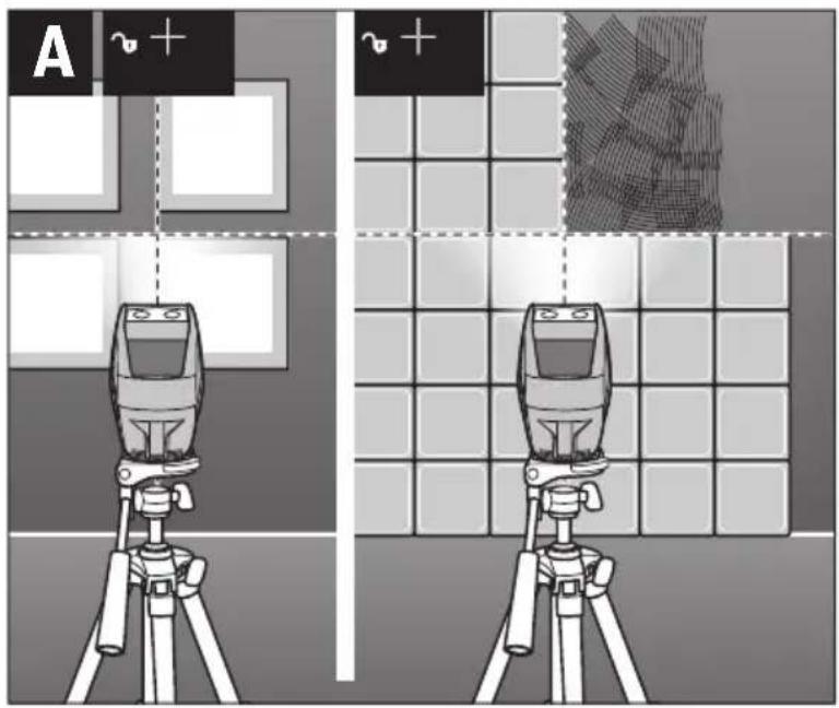
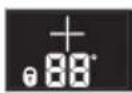
Cross-line mode (see figure A): The measuring tool generates a horizontal and a vertical laser line, the levelling of which is monitored.
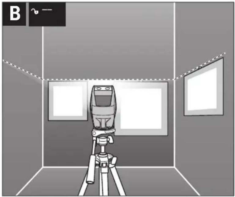
Horizontal mode (see figure B): The measuring tool generates a horizontal laser line, the levelling of which is monitored.

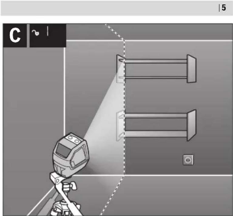
Vertical mode (see figure C): The measuring tool generates a vertical laser line, the levelling of which is monitored.
The self-levelling range of ±4^ is exceeded, self-levelling is not possible (display flashes). The laser line goes out.
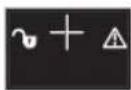
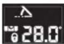
Tilt function with angle indicator operation mode:
Indication Mode
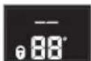
Horizontal mode.
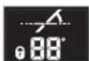
Horizontal mode. The measuring tool is tilted to the left.*
* Tilt angle h and laser lines are only indicated from an incline of > ± 2°.
Bosch Power Tools 1 618 C00 93G | (23.1.14)


26 | English
Indication Mode
Horizontal mode. The measuring tool is tilted to the right.*
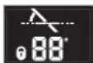
Cross-line mode (see figure D): The measuring tool generates two crossed laser lines that can be aligned as requested, and must not run vertical to each other.
Cross-line mode. The measuring tool is tilted to the left.*

Cross-line mode. The measuring tool is tilted to the right.*
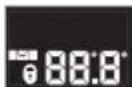
Digital spirit level. The measuring tool checks horizontal or vertical like a spirit level. Laser lines are not projected.
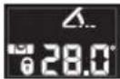
Digital spirit level. The measuring tool is tilted to the left. The smallest indicated angle is 0.1^ .
Digital spirit level. The measuring tool is tilted to the right. The smallest indicated angle is 0.1^ .
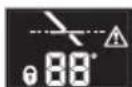
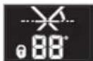
The tilt angle of ±10^ forwards (in the direction of the laser) or backwards (in the direction of the display) is exceeded (display flashes). The laser line goes out.


The calibration is active (display flashes).


The calibration is completed.
* Tilt angle h and laser lines are only indicated from an incline of > ±2°.


1 618 C00 93G | (23.1.14) Bosch Power Tools


English | 27
Additional displays:
Indication Description

The measuring tool starts.
When no button on the measuring tool is pressed for approx. 30 minutes, the measuring tool automatically switches off to save the batteries.
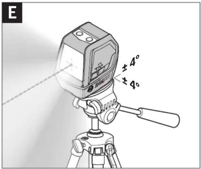
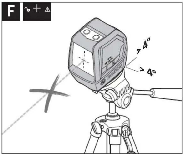
Automatic Levelling (see figures E - F)
Position the measuring tool on a level and firm support or mount it to the tripod 12.
Select one of the operating modes with automatic levelling.
After switching on, the automatic levelling function automatically compensates irregularities within the self-levelling range of ±4^ . The levelling is finished as soon as the laser lines do not move anymore. The operating mode appears in the display.
If the automatic levelling function is not possible, e. g. because the surface on which the measuring tool stands deviates by more than 4^ from the horizontal plane, the display 4 flashes and the laser is switched off automatically (see figure F). If this is the case, set up the measuring tool in a level position and wait for the self-levelling to take place. As soon as the measuring tool is once again within the self-levelling range of ±4^ , the operating mode appears in the display 4 and the laser is switched on.
When not within the self-levelling range of ±4^ , working with automatic levelling is not possible, because it cannot be assured that the laser lines run at a right angle to each other.
In case of ground vibrations or position changes during operation, the measuring tool is automatically levelled again. Upon re-levelling, check the position of the laser lines with regard to the reference points to avoid errors.
Tilt function with angle indicator
In this operation mode, the measuring tool generates a horizontal or two crossed laser lines, which can be freely aligned. The tilt angle is shown in the display.

Bosch Power Tools 1 618 C00 93G | (23.1.14)

28 | English
Align with target plate (see figure G)
The measuring tool must be calibrated with the target plate in order to ensure conformity of the tilt angle shown in the display with the projected laser line on the wall. Place the target plate on the wall. Select the cross-line mode or the vertical mode of the automatic levelling operation mode.
Ensure that the laser line passes through the upper and lower red mark on the target plate. Select a mode of the tilt function with angle indicator operation mode and project the laser line in the desired angle on the wall. When doing so, do not tilt the measuring tool more than 10^ forwards (in the direction of the laser) or backwards (in the direction of the display). Otherwise the measuring accuracy may deteriorate.
Digital spirit level
The measuring tool checks horizontal or vertical like a spirit level. Laser lines are not projected.
The side of the laser aperture serves as a reference edge. For angle measurement, align this reference edge with the horizontal or vertical plane that is to be measured. When doing so, do not tilt the measuring tool more than 5° forwards (in the direction of the laser) or backwards (in the direction of the display). Otherwise the measuring accuracy may deteriorate.
Working Advice
Calibration of the inclinometer without laser lines (e.g. before the initial operation, after transportation or severe temperature fluctuations):
Place the measuring tool on a flat table with a tilt of less than 5°. Select the digital spirit level mode. Press and hold the "Cal" calibration button 3 until the hook f appears in the display and CA1 is permanently shown. Rotate the measuring tool 180° within 15 seconds and press the "Cal" button 3 again until CA2 flashes in the display. The calibration is completed once the hook f appears in the display and CA2 is permanently shown.
Accuracy Check of the Measuring Tool
Regularly check the accuracy of the grade measurement. This is done by carrying out a reversal measurement. For this, place the measuring tool on a table and measure the grade. Turn the measuring tool by 180^ and measure the grade again. The difference of the indicated reading may not exceed by more than 0.3^ (max.).


English | 29
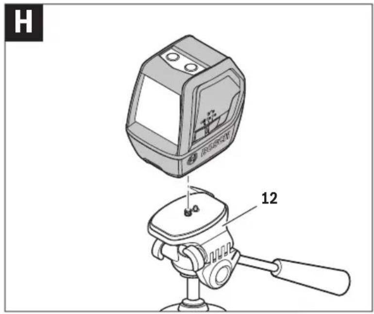
Working with the Tripod (see figure H)
A tripod 12 offers a stable, height-adjustable measuring support. Place the measuring tool via the tripod mount 6 onto the 1/4" male thread of the tripod and screw the locking screw of the tripod tight.
Laser Viewing Glasses (Accessory)
The laser viewing glasses filter out the ambient light. This makes the red light of the laser appear brighter for the eyes.
▶ Do not use the laser viewing glasses as safety goggles. The laser viewing glasses are used for improved visualisation of the laser beam, but they do not protect against laser radiation.
▶ Do not use the laser viewing glasses as sun glasses or in traffic. The laser viewing glasses do not afford complete UV protection and reduce colour perception.
Maintenance and Service
Maintenance and Cleaning
Store and transport the measuring tool only in the supplied protective pouch.
Keep the measuring tool clean at all times.
Do not immerse the measuring tool in water or other fluids.
Wipe off debris using a moist and soft cloth. Do not use any cleaning agents or solvents.
Regularly clean the surfaces at the exit opening of the laser in particular, and pay attention to any fluff of fibres.
In case of repairs, send in the measuring tool packed in its protective pouch 13.
After-sales Service and Application Service
Our after-sales service responds to your questions concerning maintenance and repair of your product as well as spare parts. Exploded views and information on spare parts can also be found under:
www.bosch-pt.com
Bosch's application service team will gladly answer questions concerning our products and their accessories.
Bosch Power Tools 1 618 C00 93G | (23.1.14)
30 | English
In all correspondence and spare parts orders, please always include the 10-digit article number given on the type plate of the measuring tool.
Great Britain
Robert Bosch Ltd. (B.S.C.)
P.O. Box 98
Broadwater Park
North Orbital Road
Denham
Uxbridge
UB 9 5HJ
At www.bosch-pt.co.uk you can order spare parts or arrange the collection of a product in need of servicing or repair.
Tel. Service: (0844) 7360109
E-Mail: boschservicecentre@bosch.com
Ireland
Origo Ltd.
Unit 23 Magna Drive
Magna Business Park
City West
Dublin 24
Tel. Service: (01) 4666700
Fax: (01) 4666888
Australia, New Zealand and Pacific Islands
Robert Bosch Australia Pty. Ltd.
Power Tools
Locked Bag 66
Clayton South VIC 3169
Customer Contact Center
Inside Australia:
Phone: (01300) 307044
Fax: (01300) 307045
Inside New Zealand:
Phone: (0800) 543353
Fax: (0800) 428570
Outside AU and NZ:
Phone: +61 3 95415555
www.bosch.com.au
1 618 C00 93G | (23.1.14) Bosch Power Tools
English | 31
Republic of South Africa
Customer service
Hotline: (011) 6519600
Gauteng - BSC Service Centre
35 Roper Street, New Centre
Johannesburg
Tel.: (011) 4939375
Fax: (011) 4930126
E-Mail: bsctools@icon.co.za
KZN - BSC Service Centre
Unit E, Almar Centre
143 Crompton Street
Pinetown
Tel.: (031) 7012120
Fax: (031) 7012446
E-Mail: bsc.dur@za.bosch.com
Western Cape - BSC Service Centre
Democracy Way, Prosperity Park
Milnerton
Tel.: (021) 5512577
Fax: (021) 5513223
E-Mail: bsc@zsd.co.za
Bosch Headquarters
Midrand, Gauteng
Tel.: (011) 6519600
Fax: (011) 6519880
E-Mail: rbsa-hq.pts@za.bosch.com
Disposal
Measuring tools, accessories and packaging should be sorted for environmental-friendly recycling.
Do not dispose of measuring tools and batteries/rechargeable batteries into household waste!
Bosch Power Tools 1 618 C00 93G | (23.1.14)

32 | Français
Only for EC countries:
According to the European Guideline 2012/19/EU, measuring tools that are no longer usable, and according to the European Guideline 2006/66/EC, defective or used battery packs/batteries, must be collected separately and disposed of in an environmentally correct manner.
Batteries no longer suitable for use can be directly returned at:
Great Britain
Robert Bosch Ltd. (B.S.C.)
P.O. Box 98
Broadwater Park
North Orbital Road
Denham
Uxbridge
UB 9 5HJ
At www.bosch-pt.co.uk you can order spare parts or arrange the collection of a product in need of servicing or repair.
Tel. Service: (0844) 7360109
E-Mail: boschservicecentre@bosch.com
Subject to change without notice.

Français
Robert Bosch (France) S.A.S.
Bosch Service Center
Telegrafvej 3
2750 Ballerup
På www.bosch-pt.dk kan der online bestilles reservedele eller oprettes en reparations ordre.
Tlf. Service Center: 44898855
Fax: 44898755
E-Mail: vaerktoej@dk.bosch.com
Bortskaffelse
Bosch Service Center
Telegrafvej 3
2750 Ballerup
Danmark
Tel.: (08) 7501820 (inom Sverige)
Fax: (011) 187691
Avfallshantering
Bosch San. ve Tic. A.S.
Ahi Evran Cad. No:1 Kat:22
Polaris Plaza
80670 Maslak/Istanbul
Bosch Uzman Ekibi +90 (0212) 367 18 88
Işıklar LTD.ŞTİ.
Kızılay Cad. No: 16/C Seyhan
Adana
Tel.: 0322 3599710
Tel.: 0322 3591379
IOI I I I I I I I I I I I I I I I I I I I I I I I I I I I I I I I I I I
natural_image
Prohibition sign with a heart symbol crossed out by a diagonal line, no text or numbers present.كمال المؤهلين
◀ ر دون مراقبة.
ن لغطر الانفبار
◀ 触ظ المعلومات
◀ Transaction on the
natural_image
Warning symbol with a triangular triangle and a central explosion or burst (no text or numbers)

- PLL 2
- BOSCH
- | Deutsch
- Deutsch
- Sicherheitshinweise
- English | 21
- Product Description and Specifications
- Intended Use
- | English
- Product Features
- Display Elements
- | English
- Assembly
- Inserting/Replacing the Batteries
- Operation
- Initial Operation
- Switching On and Off
- Operation Modes (see figures A - D)
- Indication Mode
- | English
- Indication Description
- Automatic Levelling (see figures E - F)
- Tilt function with angle indicator
- | English
- Align with target plate (see figure G)
- Digital spirit level
- Working Advice
- Calibration of the inclinometer without laser lines (e.g. before the initial operation, after transportation or severe temperature fluctuations):
- Accuracy Check of the Measuring Tool
- Working with the Tripod (see figure H)
- Laser Viewing Glasses (Accessory)
- Maintenance and Service
- Maintenance and Cleaning
- After-sales Service and Application Service
- www.bosch-pt.com
- | English
- Great Britain
- Ireland
- Australia, New Zealand and Pacific Islands
- Republic of South Africa
- Customer service
- Gauteng - BSC Service Centre
- KZN - BSC Service Centre
- Western Cape - BSC Service Centre
- Bosch Headquarters
- Disposal
- | Français
- Only for EC countries:
- Français
- Bortskaffelse
- Avfallshantering
Brand : BOSCH
Model : PLL 2 (Set)
Category : Laser level