
D91E5N0 - Basket NEFF - Free user manual and instructions
Find the device manual for free D91E5N0 NEFF in PDF.
| Product type | Suspended chimney hood |
| Brand | Neff |
| Model | D91E5N0 |
| Installation | On ceiling (or stable false ceiling) |
| Extraction mode | Air exhausted outside or recirculated air (with optional charcoal filter) |
| Recommended duct diameter | 150 mm (minimum 120 mm) |
| Minimum distance from electric hobs | 550 mm |
| Minimum distance from gas hobs | 650 mm (750 mm for model LC 97050) |
| Material | Stainless steel |
| Functions | Lighting, timer, electronic control |
| Control type | Round or rectangular buttons depending on version |
| Lighting | Integrated (type not specified) |
| Power supply | 220-240 V, 50 Hz (estimated) |
| Power cord length | 1.30 m |
| Weight (approx.) | 41 to 43 kg (similar model D91E1N0) |
| Filters | Activated charcoal filter (optional for recirculation mode) |
| Maintenance and cleaning | Clean filters regularly; use a soft cloth for stainless steel surfaces |
| Safety | Disconnect the appliance before any intervention; use appropriate ceiling anchors |
| General information | Manual available in several languages; appliance complies with WEEE directive |
Frequently Asked Questions - D91E5N0 NEFF
User questions about D91E5N0 NEFF
0 question about this device. Answer the ones you know or ask your own.
Ask a new question about this device
Download the instructions for your Basket in PDF format for free! Find your manual D91E5N0 - NEFF and take your electronic device back in hand. On this page are published all the documents necessary for the use of your device. D91E5N0 by NEFF.
USER MANUAL D91E5N0 NEFF
natural_image
Line drawing of a kitchen air conditioner unit with ventilation grilles and mounting holes (no text or symbols)natural_image
Simple line drawing of a trash bin with no text or symbols⚠️Old appliances are not worthless rubbish. Valuable raw materials can be reclaimed by recycling old appliances. Before disposing of your old appliance, render it unusable.
⚠️You received your new appliance in a protective shipping carton. All packaging materials are environmentally friendly and recyclable. Please contribute to a better environment by disposing of packaging materials in an environmentally-friendly manner.
Please ask your dealer or inquire at your local authority about current means of disposal.
⚠ The extractor hood can be used in exhaust air or circulating air mode.
The applicable regulations of the power supply company and compliance of local and national building regulations must be observed when installing air extractors (overhead and table top downdraught) in permanent dwellings.
⚠️Always mount the extractor hood over the centre of the hob.
△Minimum distance between electric hob and bottom edge of extractor hood: 550 mm, Fig. 1.
The extractor hood must not be installed over a solid fuel cooker – a potential fire hazard (e.g. flying sparks) – unless the cooker features a closed, non-removable cover and all national regulations are observed.
⚠ The smaller the gap between the extractor hood and hotplates, the greater the likelihood that droplets will form on the underside of the extractor hood.
Additional information concerning gas cookers:
When installing gas hotplates, comply with the relevant national statutory regulations (e.g. in Germany: Technische Regeln Gasinstallation TRGI).
⚠ Always comply with the currently valid regulations and installation instructions supplied by the gas appliance manufacturer.
⚠️Only one side of the extractor hood may be installed next to a high-sided unit or high wall. Gap at least 50 mm.
⚠ Minimum distance on gas hotplates between the upper edge of the trivet and lower edge of the extractor hood: 650 mm, Fig. 1
LC 97050:
750 mm, Fig. 1.
This appliance is labelled in accordance with European Directive 2002/96/EG concerning used electrical and electronic appliances (waste electrical and electronic equipment – WEEE). The guideline determines the framework for the return and recycling of used appliances as applicable throughout the EU.
natural_image
Simple line drawing of a trash bin with no text or symbolsPrior to installation
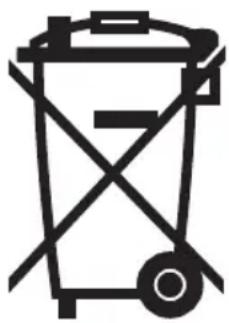
Exhaust-air mode Fig. 2
The exhaust air is discharged upwards through a ventilation shaft or directly through the outside wall into the open.
Exhaust air should neither be directed into a smoke or exhaust flue that is currently used for other purposes, nor into a shaft that is used for ventilating rooms in which stoves or fireplaces are also located.
Exhaust air may be discharged in accordance with official and statutory regulations only (e.g. national building regulations).
Local authority regulations must be observed when discharging air into smoke or exhaust flues that are not otherwise in use.
When the extractor hood is operated in exhaust-air mode simultaneously with a different burner which also makes use of the same chimney (such as gas, oil or coal-fired heaters, continuous-flow heaters, hot-water boilers) care must be taken to ensure that there is an adequate supply of fresh air which will be needed by the burner for combustion.
Safe operation is possible provided that the underpressure in the room where the burner is installed does not exceed 4 Pa (0.04 mbar).
This can be achieved if combustion air can flow through non-lockable openings, e.g. in doors, windows and via the air-intake/exhaust-air wall box or by other technical measures, such as reciprocal interlocking, etc.
If the air intake is inadequate, there is a risk of poisoning from combustion gases which are drawn back into the room.
An air-intake/exhaust-air wall box by itself is no guarantee that the limiting value will not be exceeded.
Note: When assessing the overall requirement, the combined ventilation system for the entire household must be taken into consideration. This rule does not apply to the use of cooking appliances, such as hobs and ovens.
Unrestricted operation is possible if the extractor hood is used in recirculating mode – with activated carbon filter.
If the exhaust air is going to be discharged into the open, a telescopic wall box should be fitted into the outside wall.
For optimum extractor hood efficiency:
☐ Short, smooth air exhaust pipe.
☐ As few bends in the pipe as possible.
☐ Diameter of pipe to be as large as possible and no tight bends in pipe.
If long, rough exhaust-air pipes, many pipe bends or smaller pipe diameters are used, the air extraction rate will no longer be at an optimum level and there will be an increase in noise.
☐ Round pipes: We recommend Internal diameter: 150 mm (at least 120 mm).
☐ Flat ducts must have an internal cross-section that equates to that of round pipes.
There should be no sharp bends.
∅ 120 mm approx. 113 cm
∅ 150 mm approx. 177 cm
☐ If pipes have different diameters: Insert sealing strip.
☐ For exhaust-air mode, ensure that there is an adequate supply of fresh air.
Connecting a 150 mm exhaust-air pipe:
☐ Mount the pipe directly onto the air outlet on the hood.
Connecting a 120 mm exhaust-air pipe:
☐ Place the reducing connecting piece onto the air connecting piece – Fig. 3 – and fasten the exhaust pipe to it.
☐ Attach the exhaust-air pipe to the reducing connector.
Circulating-air mode Fig. 4
☐ With activated carbon filter if exhaust-air mode is not possible.
⚠️If the extractor hood is suitable for circulating-air mode, you can purchase the complete installation set at specialist outlets.
Preparing the ceiling
☐ The ceiling must be flat and horizontal.
☐ Ensure that the ceiling is capable of providing a firm hold for mounting screws and plugs. The enclosed plugs are suitable for concrete and stonework. If the ceiling is made of any other material, use appropriate mounting components.
Weight in kg:
| Exhaust air | Recirculating air | |
| DIE975A | 32 | 34 |
| DIE995F | 48 | 50 |
| DIE945E | 41 | 43 |
| LC91150 | 41 | 43 |
| LC97050 | 41 | 43 |
| LC95950 | 32 | 34 |
| LC95150 | 35 | 37 |
| LC92950 | 41 | 43 |
| D8150N1 | 29 | 31 |
| D8150N2 | 29 | 31 |
| D91E1N0 | 41 | 43 |
We reserve the right to construction changes within the context of technical development.
Electrical connection
WARNING: THIS APPLIANCE MUST BE EARTHED
IMPORTANT: Fitting a Different Plug:
The wires in the mains lead are coloured in accordance with the following code:
Green and Yellow – Earth
Blue - Neutral
Brown – Live
If you fit your own plug, the colours of these wires may not correspond with the identifying marks on the plug terminals.
This is what you have to do:
- Connect the green and yellow (Earth) wire to the terminal in the plug marked 'E' or with the symbol (≡), or coloured green or green and yellow.
- Connect the blue (Neutral) wire to the terminal in the plug marked 'N' or coloured black.
- Connect the brown (Live) wire to the terminal marked 'L', or coloured red.
The extractor hood should only be connected to an earthed socket that has been installed according to relevant regulations.
If possible, site the earthed socket directly above the chimney panelling in the ceiling.
Electrical data:
Are to be found on the name plate inside the appliance after removal of the filter frame.
⚠️Before undertaking any repairs, always disconnect the extractor hood from the electricity supply.
Length of the connecting cable: 1.30 m.
If it is necessary to wire the extractor hood directly into the mains:
The extractor hood should only be connected to the electricity supply by a properly qualified electrician.
A separator must be installed in the household circuit. A suitable separator is a switch that has a contact gap of more than 3 mm and interrupts all poles. Such devices include circuit breakers and contactors.
⚠️If the connecting cable for this appliance is damaged, the cable must be replaced by the manufacturer or his customer service or a similarly qualified person in order to prevent serious injury to the user.
This extractor hood corresponds to EC regulations concerning RF interference suppression.
Installation
The extractor hood is designed to be fitted to the kitchen ceiling or a rigid suspended ceiling.
⚠ Ensure that the minimum distance between hotplate and extractor hood is 550 mm for electric hotplates and 650 mm (LC 97050: 750 mm) for gas hotplates.
- Mark the centre point of the extractor hood on the ceiling.
- Using the template, mark screw positions on the ceiling. Fig. 5.
- Drill the 8 mm ∅ fixing holes and insert the wall plugs into the holes. Fig. 5.
- Screw on the support frame. Fig. 5.
Installation
-
Attach the upper flue to the support frame with the 2 screws. Fig. 6.
-
Remove the protective film from the top part of the flue.
⚠ Attention: Do not damage the sensitive stainless-steel surfaces.
-
Push up the lower part of the flue and secure to prevent it from falling down. Fig. 6.
-
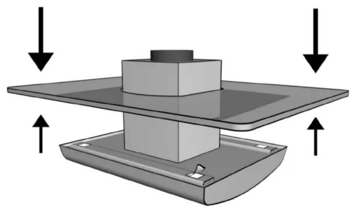
DIE 975 A only; place the glass screen on the hood. Fig. 7.
-
Install the extractor hood in the support frame and screw into position at the required height. Fig. 6.
☐ Extractor hood can be aligned via the elongated holes.
-
Connect the pipe.
-
Connect the power.
-
Very carefully push down the lower part of the flue.
-
DIE 975 A only – Raise the glass screen and remove the protective film from the adhesive strips.
Attach the glass screen and press into place. Fig. 7.
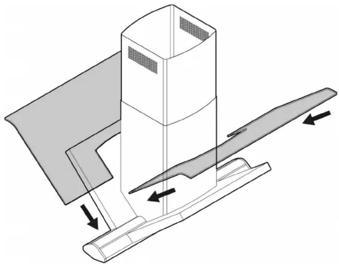
- DIE 995 F only – Install 2 glass screens. Fig. 8.
Changing over from exhaust-air to recirculating mode
☐ The electronic control system has been set up in the factory for the mode applicable to the extractor hood version which you have purchased.
☐ If it becomes necessary to change the mode, the electronic control system must also be changed over.
Change over procedure:
The extractor hood must have been connected up and should be switched off.
☐ For hood with round push buttons ...
- Press for some seconds at the same time the push buttons Light and Timer, you will have appearing in the display the symbol at the side which will be followed by the 0.
- Each time you press the Light push buttons, it is possible to change the shown value from 0 (exhaust air) to 1 (recirculation mode) and vice versa.
- Press the push button 0 to confirm choice selected in previous point.
☐ For hood with rectangular push buttons ...
- Press and hold the 0 button.
- While the ☐ is displayed, press the 📄→1 button until ┌ or = is displayed. When this has taken place, release the button.
Changing from exhaust-air to recirculating mode:
☐ goes out shortly afterwards.
The electronic control system will then have been selected to recirculating mode.
Changing from recirculation to exhaust air mode:
☐ = goes out shortly afterwards.
The electronic control system will then have been selected to exhaust air mode.
Remarques importantes
natural_image
Simple line drawing of a trash bin with no text or symbolsLC 97050: 750 mm, afb. 1.
natural_image
Simple line drawing of a trash bin with no text or symbolsnatural_image
Simple line drawing of a trash bin with no text or symbolsLC 97050: 750 mm, (Fig. 1).
natural_image
Simple line drawing of a trash bin with no text or symbolsnatural_image
Simple line drawing of a trash bin with no text or symbolsnatural_image
Simple line drawing of a trash bin with no text or symbolsΠριν την τοποθέτηση
natural_image
Simple line drawing of a trash bin with no text or symbolsFöre monteringen
Frånluft bild 2
LC 97050: 750 mm, fig. 1.
natural_image
Simple line drawing of a trash bin with no text or symbolsFør montasjen
Utløpsdrift fig. 2
natural_image
Simple line drawing of a trash bin with no text or symbolsEnnen asennusta
natural_image
Simple line drawing of a trash bin with no text or symbolsInden monteringen
Aftræk Fig. 2
natural_image
Simple line drawing of a trash bin with no text or symbolsAtik hava modu Res. 2
natural_image
3D diagram of a mechanical press or fixture with a cylindrical component and downward arrows indicating force or motion (no text or symbols)Abb. 3
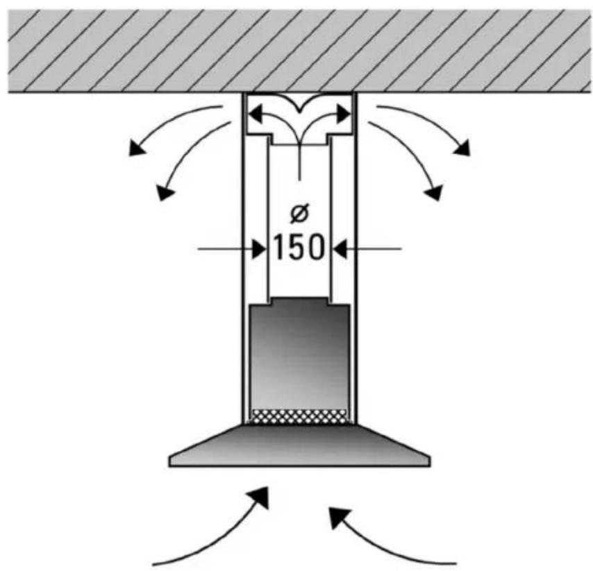
Abb. 4
Abb. 5
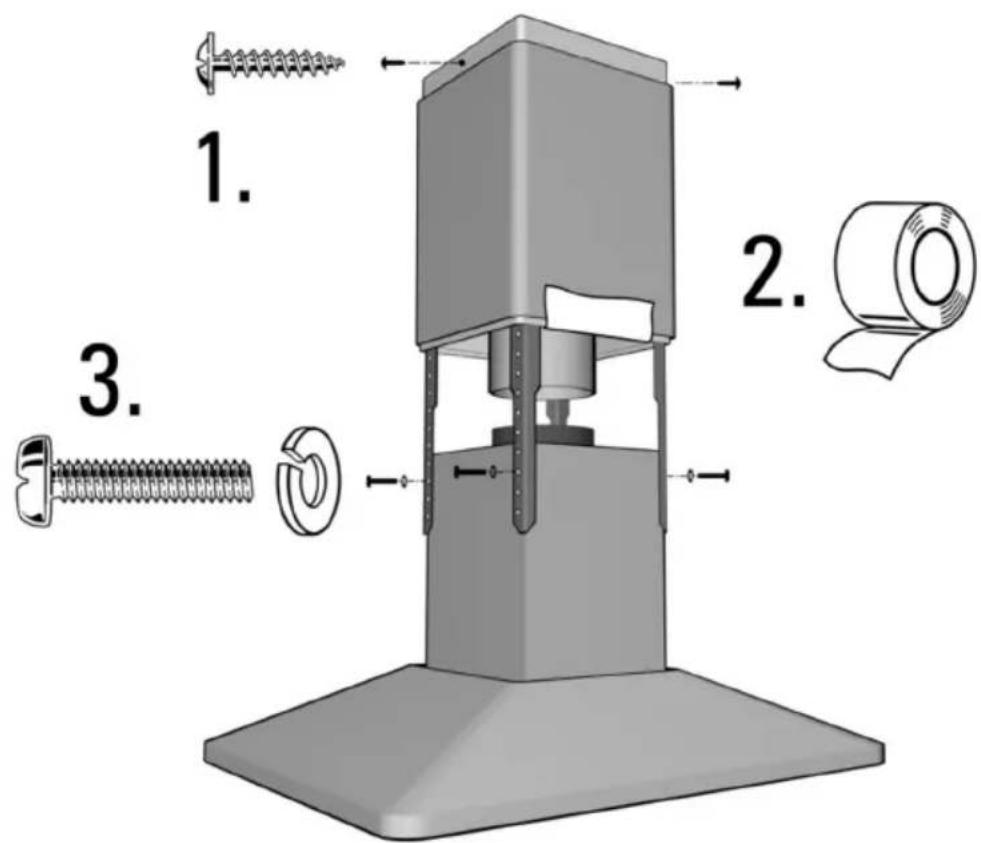
Abb. 6
natural_image
Mechanical assembly diagram showing a central block mounted on a platform with two downward arrows indicating force or movement (no text or symbols present)Abb. 7
natural_image
Technical diagram of a mechanical assembly with directional arrows indicating motion or force (no text or symbols present)Abb. 8