
Classic 30 - Receiver PEAVEY - Free user manual and instructions
Find the device manual for free Classic 30 PEAVEY in PDF.
| Product Type | Tube Guitar Amplifier |
| Output Power | 30 Watts RMS |
| Power Tubes | 4 x EL84 |
| Preamp Tubes | 3 x 12AX7 |
| Channels | 2 (Normal and Lead) |
| Equalizer | 3-band passive (Bass, Mid, Treble) |
| Reverb | Spring reverb with level control and optional footswitch |
| Effects Loop | Yes (Send and Return) |
| Controls | Normal Volume, Pre Gain, Post Gain, Boost, Reverb, Presence, 3-band EQ |
| Internal Speaker | 1 x 12 inches (approx) |
| Speaker Output Impedance | 8 ohms internal; extension jack 8 ohms minimum |
| Inputs | 1 x 1/4 inch instrument input |
| Compatible Footswitches | Channel switching, Boost, Reverb (Peavey 03054360, 03051000) |
| Dimensions (approx) | 50 x 25 x 25 cm |
| Weight (approx) | 20 kg |
| Power Supply | Mains 110-120V or 220-240V (depending on version), specified fuse type |
| Power Consumption (approx) | 100 W |
| Cleaning | Dry cloth only |
| Repairability | Refer to a Peavey authorized technician; do not open the chassis |
| Maintenance | Store in dry place, avoid humidity and heat sources |
| Warranty | Standard Peavey (see document) |
Frequently Asked Questions - Classic 30 PEAVEY
User questions about Classic 30 PEAVEY
0 question about this device. Answer the ones you know or ask your own.
Ask a new question about this device
Download the instructions for your Receiver in PDF format for free! Find your manual Classic 30 - PEAVEY and take your electronic device back in hand. On this page are published all the documents necessary for the use of your device. Classic 30 by PEAVEY.
USER MANUAL Classic 30 PEAVEY
Classic® 30 / Delta Blues Amplifiers
Operating Manual
natural_image
Exterior view of a beige audio amplifier with a black grille and 'Delta Blues' branding (no additional text or symbols visible)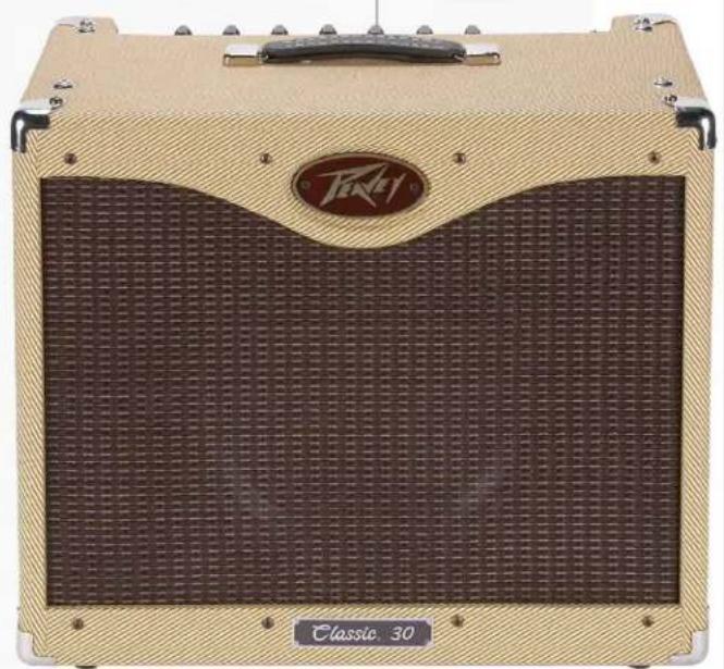
natural_image
Exterior view of a beige acoustic guitar with textured grille and 'Classic 30' label (no readable text beyond branding)
Intended to alert the user to the presence of uninsulated "dangerous voltage" within the product's enclosure that may be of sufficient magnitude to constitute a risk of electric shock to persons.
Intended to alert the user of the presence of important operating and maintenance (servicing) instructions in the literature accompanying the product.
CAUTION: Risk of electrical shock — DO NOT OPEN!
CAUTION: To reduce the risk of electric shock, do not remove cover. No user serviceable parts inside. Refer servicing to qualified service personnel.
WARNING: To prevent electrical shock or fire hazard, this apparatus should not be exposed to rain or moisture, and objects filled with liquids, such as vases, should not be placed on this apparatus. Before using this apparatus, read the operating guide for further warnings.


Protective earthing terminal. The apparatus should be connected to a mains socket outlet with a protective earthing connection.

IMPORTANT SAFETY INSTRUCTIONS
WARNING: When using electrical products, basic cautions should always be followed, including the following:
-
Read these instructions.
-
Keep these instructions.
-
Heed all warnings.
-
Follow all instructions.
-
Do not use this apparatus near water.
-
Clean only with a dry cloth.
-
Do not block any of the ventilation openings. Install in accordance with manufacturer's instructions.
-
Do not install near any heat sources such as radiators, heat registers, stoves or other apparatus (including amplifiers) that produce heat.
-
Do not defeat the safety purpose of the polarized or grounding-type plug. A polarized plug has two blades with one wider than the other. A grounding type plug has two blades and a third grounding plug. The wide blade or third prong is provided for your safety. If the provided plug does not fit into your outlet, consult an electrician for replacement of the obsolete outlet.
-
Protect the power cord from being walked on or pinched, particularly at plugs, convenience receptacles, and the point they exit from the apparatus.
-
Only use attachments/accessories provided by the manufacturer.
-
Use only with a cart, stand, tripod, bracket, or table specified by the manufacturer, or sold with the apparatus. When a cart is used, use caution when moving the cart/apparatus combination to avoid injury from tip-over.
-
Unplug this apparatus during lightning storms or when unused for long periods of time.
-
Refer all servicing to qualified service personnel. Servicing is required when the apparatus has been damaged in any way, such as power-supply cord or plug is damaged, liquid has been spilled or objects have fallen into the apparatus, the apparatus has been exposed to rain or moisture, does not operate normally, or has been dropped.
-
Never break off the ground pin. Write for our free booklet "Shock Hazard and Grounding." Connect only to a power supply of the type marked on the unit adjacent to the power supply cord.
-
If this product is to be mounted in an equipment rack, rear support should be provided.
-
Note for UK only: If the colors of the wires in the mains lead of this unit do not correspond with the terminals in your plug, proceed as follows: a) The wire that is colored green and yellow must be connected to the terminal that is marked by the letter E, the earth symbol, colored green or colored green and yellow. b) The wire that is colored blue must be connected to the terminal that is marked with the letter N or the color black. c) The wire that is colored brown must be connected to the terminal that is marked with the letter L or the color red.
-
This electrical apparatus should not be exposed to dripping or splashing and care should be taken not to place objects containing liquids, such as vases, upon the apparatus.
-
The on/off switch in this unit does not break both sides of the primary mains. Hazardous energy can be present inside the chassis when the on/off switch is in the off position. The mains plug or appliance coupler is used as the disconnect device, the disconnect device shall remain readily operable.
-
Exposure to extremely high noise levels may cause a permanent hearing loss. Individuals vary considerably in susceptibility to noise-induced hearing loss, but nearly everyone will lose some hearing if exposed to sufficiently intense noise for a sufficient time. The U.S. Government's Occupational Safety and Health Administration (OSHA) has specified the following permissible noise level exposures:
Duration Per Day In Hours Sound Level dBA, Slow Response
| 8 90 | |
| 6 92 | |
| 4 95 | |
| 3 97 | |
| 2 100 | |
| 1 1/2 102 | |
| 1 105 | |
| 1/2 | 110 |
| 1/4 or less | |
According to OSHA, any exposure in excess of the above permissible limits could result in some hearing loss. Earplugs or protectors to the ear canals or over the ears must be worn when operating this amplification system in order to prevent a permanent hearing loss, if exposure is in excess of the limits as set forth above. To ensure against potentially dangerous exposure to high sound pressure levels, it is recommended that all persons exposed to equipment capable of producing high sound pressure levels such as this amplification system be protected by hearing protectors while this unit is in operation.
SAVE THESE INSTRUCTIONS!
a) The wire that is colored green and yellow must be connected to the terminal that is marked by the letter E, the earth symbol, colored green or colored green and yellow.
b) The wire that is colored blue must be connected to the terminal that is marked with the letter N or the color black.
c) The wire that is colored brown must be connected to the terminal that is marked with the letter L or the color red.
Logo referenced in Directive 2002/96/EC Annex OJ(L)37/38,13.02.03 and defined in EN 50419: 2005
The bar is the symbol for marking of new waste and is applied only to equipment manufactured after 13 August 2005
Correct Disposal of this product. This marking indicates that this product should not be disposed with other house hold wastes throughout the EU. To prevent possible harm to the environment or human health from uncontrolled waste disposal, recycle it responsibly to promote the sustainable reuse of material resources. To return your used device, please use the return and collection systems, or contact the retailer where the product was purchased. They can take this product for environmental safe recycling.

FCC Compliancy Statement
This device complies with Part 15 of the FCC rules. Operation is subject to the following two conditions: (1) this device may not cause harmful interference, and (2) this device must accept any interference received, that may cause undesired operation.
Warning: Changes or modifications to the equipment not approved by Peavey Electronics Corp. can void the user's authority to use the equipment.
Note - This equipment has been tested and found to comply with the limits for a Class B digital device, pursuant to Part 15 of the FCC Rules. These limits are designed to provide reasonable protection against harmful interference in a residential installation. This equipment generates, uses and can radiate radio frequency energy and, if not installed and used in accordance with the instructions, may cause harmful interference to radio communications. However, there is no guarantee that interference will not occur in a particular installation. If this equipment does cause harmful interference to radio or television reception, which can be determined by turning the equipment off and on, the user is encouraged to try and correct the interference by one or more of the following measures.
- Reorient or relocate the receiving antenna.
- Increase the separation between the equipment and receiver.
- Connect the equipment into an outlet on a circuit different from that to which the receiver is connected.
- Consult the dealer or an experienced radio/TV technician for help.
CAN ICES-3(B)/NMB/3(B)

ENGLISH
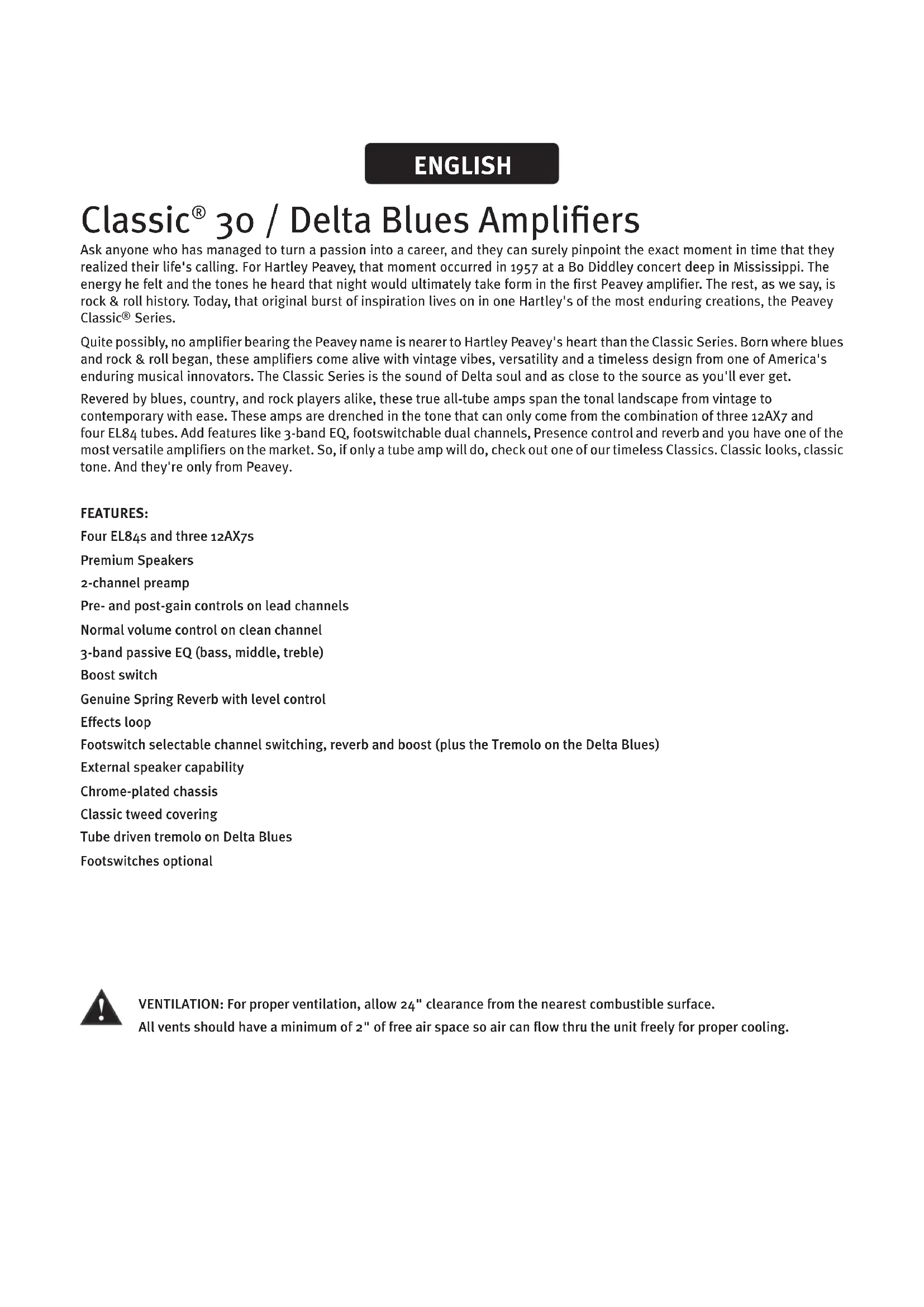
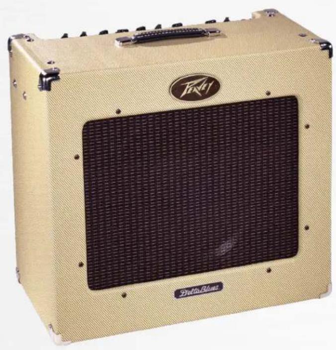
Classic® 30 / Delta Blues Amplifiers
Ask anyone who has managed to turn a passion into a career, and they can surely pinpoint the exact moment in time that they realized their life's calling. For Hartley Peavey, that moment occurred in 1957 at a Bo Diddley concert deep in Mississippi. The energy he felt and the tones he heard that night would ultimately take form in the first Peavey amplifier. The rest, as we say, is rock & roll history. Today, that original burst of inspiration lives on in one Hartley's of the most enduring creations, the Peavey Classic® Series.
Quite possibly, no amplifier bearing the Peavey name is nearer to Hartley Peavey's heart than the Classic Series. Born where blues and rock & roll began, these amplifiers come alive with vintage vibes, versatility and a timeless design from one of America's enduring musical innovators. The Classic Series is the sound of Delta soul and as close to the source as you'll ever get.
Revered by blues, country, and rock players alike, these true all-tube amps span the tonal landscape from vintage to contemporary with ease. These amps are drenched in the tone that can only come from the combination of three 12AX7 and four EL84 tubes. Add features like 3-band EQ, footswitchable dual channels, Presence control and reverb and you have one of the most versatile amplifiers on the market. So, if only a tube amp will do, check out one of our timeless Classics. Classic looks, classic tone. And they're only from Peavey.
FEATURES:
Four EL84s and three 12AX7s
Premium Speakers
2-channel preamp
Pre- and post-gain controls on lead channels
Normal volume control on clean channel
3-band passive EQ (bass, middle, treble)
Boost switch
Genuine Spring Reverb with level control
Effects loop
Footswitch selectable channel switching, reverb and boost (plus the Tremolo on the Delta Blues)
External speaker capability
Chrome-plated chassis
Tube driven tremolo on Delta Blues
Footswitches optional

VENTILATION: For proper ventilation, allow 24" clearance from the nearest combustible surface.
All vents should have a minimum of 2" of free air space so air can flow thru the unit freely for proper cooling.
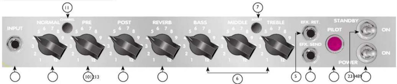
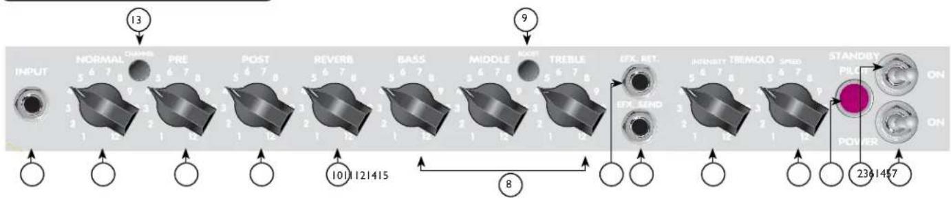
Classic® 30 Control Panel
Switch to "ON" position to activate.
STANDBY SWITCH
Allows amp to be placed in standby or active mode. In standby mode the tubes remain hot, but the amplifier is not operational.
PILOT LIGHT LED
Illuminates when AC power is being supplied to the unit.
EFFECTS SEND
Output for supplying signal to external effects or signal processing equipment.
EFFECTS RETURN
Input for returning signals from external effects or signal processing equipment.
TREBLE, MIDDLE, AND BASS EQ
Passive tone controls that regulate high, mid, and low frequencies, respectively.
BOOST SWITCH
Boosts the overall system gain. Depress to the "in" position to activate.
REVERB
Reverberation is an echo effect. Rotate clockwise to increase the effect. Remote footswitch can control ON/OFF.
POST GAIN
Controls the overall volume level of the Lead channel. The final level adjustment should be made after the desired sound has been achieved.
PRE GAIN
Controls the input volume level of the Lead channel.
CHANNEL SELECT SWITCH
Allows selection of the Lead or Normal channel.
NOTE: Channel selection may also be achieved by the remote footswitch. If remote selection is desired, the channel switch must be in the “in” (Lead) position.
NORMAL GAIN
Controls the volume level of the Normal channel.
INPUT
The input jack will accept signals from all types of guitar pickups. Be sure to use a high-quality shielded cable to connect the guitar to the amplifier.
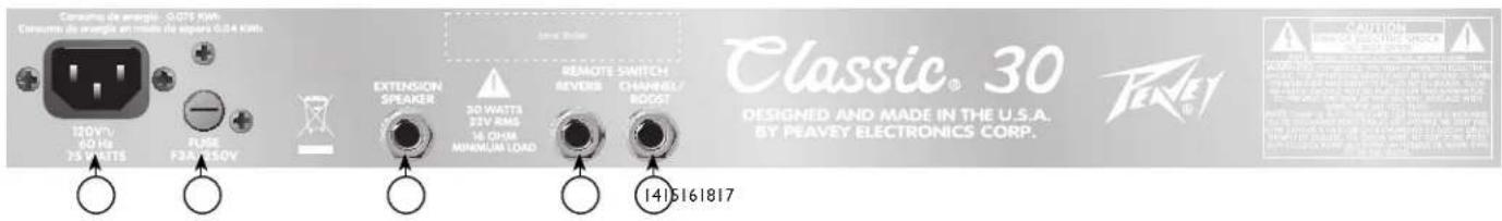
⑭ REMOTE CHANNEL/BOOST SWITCH JACK
This is provided for the connection of the optional remote footswitch. The footswitch is used to select the Lead or Normal channels and activate the boost. When using the remote footswitch, always insert the plug fully (second click) to ensure proper operation. (requires Peavey footswitch 03054360)
15 REVERB SWITCH JACK
This is provided for the connection of the optional remote footswitch. The footswitch is used to defeat reverb. (requires Peavey footswitch 03051000)
16 EXTERNAL SPEAKER JACK
This is provided for connection of an external speaker cabinet. Minimum total impedance is 8 ohms.
Caution: The on/off switch in this unit does not break both sides of the primary mains. Hazardous energy can be present inside the chassis even when the on/off switch is in the OFF position.
17 FUSE
The fuse is located within the cap of the fuseholder. If the fuse should fail, IT MUST BE REPLACED WITH THE SAME TYPE AND VALUE IN ORDER TO AVOID DAMAGE TO THE EQUIPMENT AND TO PREVENT VOIDING THE WARRANTY. If the amp repeatedly blows fuses, it should be taken to a qualified service center for repair.

WARNING: THE FUSE SHOULD ONLY BE REPLACED WHEN THE POWER CORD HAS BEEN DISCONNECTED FROM ITS POWER SOURCE.

AC POWER INLET:
This is the receptacle for an IEC line cord, which provides AC power to the unit. Connect the line cord to this connector to provide power to the unit. Damage to the equipment may result if improper line voltage is used. (See line voltage marking on unit).

Never break off the ground pin on any equipment. It is provided for your safety. If the outlet used does not have a ground pin, a suitable grounding adapter should be used, and the third wire should be grounded properly. To prevent the risk of shock or fire hazard, always make sure that the amplifier and all associated equipment is properly grounded.
NOTE: FOR UK ONLY
As the colors of the wires in the mains lead of this apparatus may not correspond with the colored markings identifying the terminals in your plug, proceed as follows: (1) The wire that is colored green and yellow must be connected to the terminal that is marked by the letter E, or by the Earth symbol, or colored green or green and yellow. (2) The wire that is colored blue must be connected to the terminal that is marked with the letter N, or the color black. (3) The wire that is colored brown must be connected to the terminal that is marked with the letter L, or the color red.
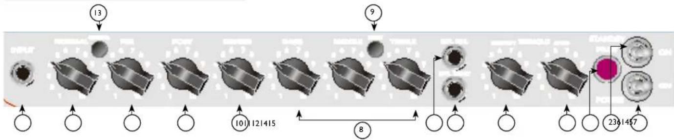
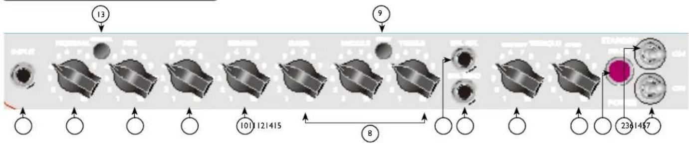
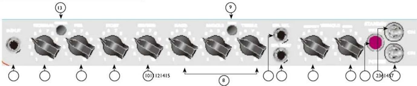
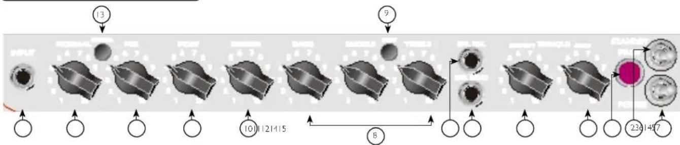
Delta Blues® Control Panel
flowchart
graph LR
    INPUT["INPUT"] --> NORMAL["NORMAL ON/OFFS"]
    NORMAL --> PRE["PRE"]
    PRE --> POST["POST"]
    POST --> REVERB["REVERB"]
    REVERB --> BASS["BASS"]
    BASS --> MIDDLE["MIDDLE"]
    MIDDLE --> TREBLE["TREBLE"]
    TREBLE --> EFX_RET["EFX RET."]
    TREBLE --> EFX_SEND["EFX SEND"]
    EFX_RET --> INTENSITT["TREMOLO SPEED"]
    INTENSITT --> STANDBY["STANDBY PILLION ON POWER ON"]
    STANDBY --> POWER["POWER ON 2361457"]
POWER SWITCH
Switch to "ON" position to turn on.
STANDBY SWITCH
This two-way switch allows the amp to be placed in the STANDBY mode. In the STANDBY position the tubes stay hot but the amplifier is not operational. Switching to the ON position places the amp in active mode.
PILOT LIGHT
Illuminates when AC power is being supplied to the unit.
TREMOLO SPEED
The speed control determines the rate at which the signal is modulated. This control varies the speed of the Tremolo master oscillator and should provide any speed desired for modern music. Clockwise rotation of the speed control increases the speed of the modulation of the tremolo. The Tremolo feature is defeatable from a remote footswitch.
TREMOLO INTENSITY
The intensity control is used to vary the amount of amplitude modulation of the clean signal. It can be adjusted from barely perceptible to dramatic modulation. Clockwise rotation of the intensity control increases the depth of the tremolo.
EFFECTS RETURN
Input for returning signals to external effects or signal processing equipment.
EFFECTS SEND
Output for supplying signal to external effects or signal processing equipment.
TREBLE, MIDDLE AND BASS EQ
Passive tone controls that regulate high, mid, and low frequencies, respectively.
BOOST SWITCH
Boosts the overall system gain. Depress to the "in" position to activate.
REVERB
Reverberation is an echo effect. Rotate clockwise to increase the effect.
POST GAIN
Controls the overall volume level of the Lead channel. The final level adjustment should be made after the desired sound has been activated.
PRE GAIN
Controls the input volume level of the Lead channel.
CHANNEL SELECT SWITCH
Allows selection of the Lead or Normal channel.
Note: Channel selection may also be achieved by the remote footswitch. If remote selection is desired, the channel switch must be in the "in" (Lead) position.
NORMAL GAIN
Controls the volume level of the Normal channel.
INPUT
The input jack will accept signals from all types of guitar pickups. Be sure to use a high-quality shielded cable to connect the guitar to the amplifier.
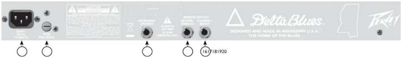
16 REMOTE CHANNEL/BOOST SWITCH JACKS
This is provided for the connection of the optional remote footswitch. The footswitch is used to select the Lead or Normal channels and activate the boost. When using the remote footswitch, always insert the plug fully (second click) to ensure proper operation. (requires Peavey footswitch 03330850)
17 REVERB SWITCH JACK
This is provided for the connection of the optional remote footswitch. The footswitch is used to defeat reverb. (requires Peavey footswitch 03330850)
18 EXTERNAL SPEAKER JACK
This is provided for connection of an external speaker cabinet. Minimum total impedance is 16 ohms.
Caution: The on/off switch in this unit does not break both sides of the primary mains. Hazardous energy can be present inside the chassis even when the on/off switch is in the OFF position.
19 FUSE
The fuse is located within the cap of the fuseholder. If the fuse should fail, IT MUST BE REPLACED WITH THE SAME TYPE AND VALUE IN ORDER TO AVOID DAMAGE TO THE EQUIPMENT AND TO PREVENT VOIDING THE WARRANTY. If the amp repeatedly blows fuses, it should be taken to a qualified service center for repair.
20 AC POWER INLET:
This is the receptacle for an IEC line cord, which provides AC power to the unit. Connect the line cord to this connector to provide power to the unit. Damage to the equipment may result if improper line voltage is used. (See line voltage marking on unit).
Never break off the ground pin on any equipment. It is provided for your safety. If the outlet used does not have a ground pin, a suitable grounding adapter should be used, and the third wire should be grounded properly. To prevent the risk of shock or fire hazard, always make sure that the amplifier and all associated equipment is properly grounded.
NOTE: FOR UK ONLY
As the colors of the wires in the mains lead of this apparatus may not correspond with the colored markings identifying the terminals in your plug, proceed as follows: (1) The wire that is colored green and yellow must be connected to the terminal that is marked by the letter E, or by the Earth symbol, or colored green or green and yellow. (2) The wire that is colored blue must be connected to the terminal that is marked with the letter N, or the color black. (3) The wire that is colored brown must be connected to the terminal that is marked with the letter L, or the color red.


Classic® 30
All-Tube Guitar Amplifier SPECIFICATIONS
POWER AMPLIFIER SECTION
Four 6BQ5/EL84s with 12AX7 driver
Rated Power & Load:
30 W RMS into 16 or 8 ohms
Power @ Clipping (Typically):
(5% THD, 1 kHz, 120 VAC line)
30 W RMS into 16 or 8 ohms
(Bias must be reduced to measure.)
Frequency Response:
+0, -2 dB, 50 Hz to 15 kHz, @ 20 W RMS into
16 ohms
Hum & Noise:
No greater than 80 dB below rated power
Power Consumption:
150 watts, 50/60 Hz, 120 VAC (Domestic)
PREAMP SECTION
Two 12AX7's
The following specs are measured @ 1 kHz with the controls preset as follows:
Pre & Post (lead) @ 0
Reverb Level @ 0
Bass & Treble EQ @ 12
Middle EQ @ 0
Channel Select Out
Boost Switch Out
Nominal level is with Input Gain @ 6
Minimum level is with Input Gain @ 12
Preamp Normal Input:
Impedance: Very high Z, 470 K ohms
Lead Channel (Post Gain @ 12):
Nominal Input Level:
-40 dBV, 10 mV RMS
Minimum Input Level:
-70 dBV, 0.3 mV RMS
Normal Channel (Post Gain @ 12):
Nominal Input Level:
-17 dBV, 140 mV RMS
Minimum Input Level:
-28 dBV, 40 mV RMS
Maximum Input Level:
0 dBV, 1.0 V RMS
Equalization:
(Lead and Normal Channels)
Custom bass, middle, and treble passive-type EQ
Effects Send:
Load Impedance: 1 K ohm or greater
Nominal Output Level: -6 dBV, 0.5 V RMS
Effects Return:
Impedance: High Z, 2 M ohms
Designed Input Level: -6 dBV, 0.5 V RMS
(Switching jack provides Effects Send to Effects
Return connection when not used.)
External Footswitch Function:
Jack 1: Reverb Defeat (when reverb control is raised)
Jack 2: Normal/Lead Channel Select (when Lead activated), Boost on/off
Speaker (Combo Only):
One 12" Blue Marvel, 16 ohms
Delta Blues™
All-Tube Guitar Amplifier SPECIFICATIONS
POWER AMPLIFIER SECTION
Four 6BQ5/EL84's with 12AX7 driver
Rated Power & Load:
30 watts RMS into 16 or 8 ohms
Power @ Clipping (Typically):
(5% THD, 1 kHz, 120 V AC line)
30 watts RMS into 16 or 8 ohms
(Bias must be reduced to measure)
Frequency Response:
+0, -2 dB, 50 Hz to 15 kHz,
@ 20 watts RMS into 16 ohms
Hum & Noise:
Greater than 80 dB below rated power
Power Consumption:
150 watts, 50/60 Hz, 120 VAC
(Domestic)
PREAMP SECTION
Two 12AX7's
The following specs are measured
@ 1 kHz with the controls preset as follows:
Pre & Post (lead) @ 0
Reverb Level @ 0
Bass & Treble EQ @ 12
Middle EQ @ 0
Channel Select Out
Boost Switch Out
Nominal level is with Input Gain @ 6.
Minimum level is with Input Gain @ 12.
Preamp Normal Input:
Impedance: Very high Z, 470 K ohms
Lead Channel
(Post Gain @ 12):
Nominal Input Level: -40 dBV, 10 mV RMS
Minimum Input Level: -70 dBV, 0.3 mV RMS
Normal Channel:
Nominal Input Level: -17 dBV, 140 mV RMS
Minimum Input Level: -28 dBV, 40 mV RMS
Maximum Input Level: 0 dBV, 1.0 V RMS
Equalization:
(Lead and Normal Channels)
Custom bass, middle, and treble passive-type EQ
Effects Send:
Load Impedance: 1 K ohm or greater
Nominal Output Level: -6 dBV, 0.5 V RMS
Effects Return:
Impedance: High Z, 2 M ohms
Designed Input Level: -6 dBV,
0.5 V RMS (Switching jack
provides Effects Send to Effects
Return connection when not used.)
External Footswitch Function:
Jack 1: Reverb Defeat (when reverb control is raised), Tremolo on/off
Jack 2: Normal/Lead Channel Select (when Lead activated), Boost on/off
DEUTSCH
Classic® 30 / Delta Blues Verstärker
14 REMOTE CHANNEL/BOOST SCHALTERBUCHSE
As the colors of the wires in the mains lead of this apparatus may not correspond with the colored markings identifying the terminals in your plug, proceed as follows: (1) The wire that is colored green and yellow must be connected to the terminal that is marked by the letter E, or by the Earth symbol, or colored green or green and yellow. (2) The wire that is colored blue must be connected to the terminal that is marked with the letter N, or the color black. (3) The wire that is colored brown must be connected to the terminal that is marked with the letter L, or the color red.
As the colors of the wires in the mains lead of this apparatus may not correspond with the colored markings identifying the terminals in your plug, proceed as follows: (1) The wire that is colored green and yellow must be connected to the terminal that is marked by the letter E, or by the Earth symbol, or colored green or green and yellow. (2) The wire that is colored blue must be connected to the terminal that is marked with the letter N, or the color black. (3) The wire that is colored brown must be connected to the terminal that is marked with the letter L, or the color red.
FRANCAIS
Amplificateurs Classic® 30 / Delta Blues
TREBLE, MIDDLE ET BASS EQ
14 COMMUTATEUR REMOTE CHANNEL/BOOST
As the colors of the wires in the mains lead of this apparatus may not correspond with the colored markings identifying the terminals in your plug, proceed as follows: (1) The wire that is colored green and yellow must be connected to the terminal that is marked by the letter E, or by the Earth symbol, or colored green or green and yellow. (2) The wire that is colored blue must be connected to the terminal that is marked with the letter N, or the color black. (3) The wire that is colored brown must be connected to the terminal that is marked with the letter L, or the color red.
Panneau de commandes Delta Blues ^AE
flowchart
graph LR
    A["Cell Division"] --> B["Cell 1"]
    B --> C["Cell 2"]
    C --> D["Cell 3"]
    D --> E["Cell 4"]
    E --> F["Cell 5"]
    F --> G["Cell 6"]
    G --> H["Cell 7"]
    H --> I["Cell 8"]
    I --> J["Cell 9"]
    J --> K["Cell 10"]
    K --> L["Cell 11"]
    L --> M["Cell 12"]
    M --> N["Cell 13"]
    N --> O["Cell 14"]
    O --> P["Cell 15"]
    P --> Q["Cell 16"]
    Q --> R["Cell 17"]
    R --> S["Cell 18"]
    S --> T["Cell 19"]
    T --> U["Cell 20"]
    U --> V["Cell 21"]
    V --> W["Cell 22"]
    W --> X["Cell 23"]
    X --> Y["Cell 24"]
    Y --> Z["Cell 25"]
    Z --> AA["Cell 26"]
    AA --> AB["Cell 27"]
    AB --> AC["Cell 28"]
    AC --> AD["Cell 29"]
    AD --> AE["Cell 30"]
INTERRUPTEUR POWER
TREBLE, MIDDLE ET BASS EQ
As the colors of the wires in the mains lead of this apparatus may not correspond with the colored markings identifying the terminals in your plug, proceed as follows: (1) The wire that is colored green and yellow must be connected to the terminal that is marked by the letter E, or by the Earth symbol, or colored green or green and yellow. (2) The wire that is colored blue must be connected to the terminal that is marked with the letter N, or the color black. (3) The wire that is colored brown must be connected to the terminal that is marked with the letter L, or the color red.


ITALIANO
Amplificatori Classic® 30 / Delta Blues
TREBLE, MIDDLE E BASS EQ
14 JACK INTERRUTTORE REMOTE CHANNEL/BOOST
As the colors of the wires in the mains lead of this apparatus may not correspond with the colored markings identifying the terminals in your plug, proceed as follows: (1) The wire that is colored green and yellow must be connected to the terminal that is marked by the letter E, or by the Earth symbol, or colored green or green and yellow. (2) The wire that is colored blue must be connected to the terminal that is marked with the letter N, or the color black. (3) The wire that is colored brown must be connected to the terminal that is marked with the letter L, or the color red.
TREBLE, MIDDLE E BASS EQ
As the colors of the wires in the mains lead of this apparatus may not correspond with the colored markings identifying the terminals in your plug, proceed as follows: (1) The wire that is colored green and yellow must be connected to the terminal that is marked by the letter E, or by the Earth symbol, or colored green or green and yellow. (2) The wire that is colored blue must be connected to the terminal that is marked with the letter N, or the color black. (3) The wire that is colored brown must be connected to the terminal that is marked with the letter L, or the color red.


ESPA—OL
Amplificadores Classic® 30 / Delta Blues
TREBLE, MIDDLE Y BASS EQ
As the colors of the wires in the mains lead of this apparatus may not correspond with the colored markings identifying the terminals in your plug, proceed as follows: (1) The wire that is colored green and yellow must be connected to the terminal that is marked by the letter E, or by the Earth symbol, or colored green or green and yellow. (2) The wire that is colored blue must be connected to the terminal that is marked with the letter N, or the color black. (3) The wire that is colored brown must be connected to the terminal that is marked with the letter L, or the color red.
Delta Blues ^E Panel de Control
flowchart
graph LR
    A["Cell Division"] --> B["Cell 1"]
    B --> C["Cell 2"]
    C --> D["Cell 3"]
    D --> E["Cell 4"]
    E --> F["Cell 5"]
    F --> G["Cell 6"]
    G --> H["Cell 7"]
    H --> I["Cell 8"]
    I --> J["Cell Fusion"]
    style A fill:#f9f,stroke:#333
    style B fill:#ccf,stroke:#333
    style C fill:#ccf,stroke:#333
    style D fill:#ccf,stroke:#333
    style E fill:#ccf,stroke:#333
    style F fill:#ccf,stroke:#333
    style G fill:#ccf,stroke:#333
    style H fill:#ccf,stroke:#333
    style I fill:#ccf,stroke:#333
    style J fill:#ccf,stroke:#333
INTERRUPTOR POWER
TREBLE, MIDDLE Y BASS EQ
As the colors of the wires in the mains lead of this apparatus may not correspond with the colored markings identifying the terminals in your plug, proceed as follows: (1) The wire that is colored green and yellow must be connected to the terminal that is marked by the letter E, or by the Earth symbol, or colored green or green and yellow. (2) The wire that is colored blue must be connected to the terminal that is marked with the letter N, or the color black. (3) The wire that is colored brown must be connected to the terminal that is marked with the letter L, or the color red.
PORTUGU S
Amplificadores Classic® 30/Delta Blues
TREBLE, MIDDLE, e BASS EQ
14 CONECTOR DE CHAVE REMOTE CHANNEL/BOOST
As the colors of the wires in the mains lead of this apparatus may not correspond with the colored markings identifying the terminals in your plug, proceed as follows: (1) The wire that is colored green and yellow must be connected to the terminal that is marked by the letter E, or by the Earth symbol, or colored green or green and yellow. (2) The wire that is colored blue must be connected to the terminal that is marked with the letter N, or the color black. (3) The wire that is colored brown must be connected to the terminal that is marked with the letter L, or the color red.
Painel de controle do Delta Blues ^AE
flowchart
graph LR
    A["Cell Division"] --> B["Cell 1"]
    B --> C["Cell 2"]
    C --> D["Cell 3"]
    D --> E["Cell 4"]
    E --> F["Cell 5"]
    F --> G["Cell 6"]
    G --> H["Cell 7"]
    H --> I["Cell 8"]
    I --> J["Cell Fusion"]
    style A fill:#f9f,stroke:#333
    style B fill:#ccf,stroke:#333
    style C fill:#ccf,stroke:#333
    style D fill:#ccf,stroke:#333
    style E fill:#ccf,stroke:#333
    style F fill:#ccf,stroke:#333
    style G fill:#ccf,stroke:#333
    style H fill:#ccf,stroke:#333
    style I fill:#ccf,stroke:#333
    style J fill:#ccf,stroke:#333
CHAVE POWER
TREBLE, MIDDLE e BASS EQ
As the colors of the wires in the mains lead of this apparatus may not correspond with the colored markings identifying the terminals in your plug, proceed as follows: (1) The wire that is colored green and yellow must be connected to the terminal that is marked by the letter E, or by the Earth symbol, or colored green or green and yellow. (2) The wire that is colored blue must be connected to the terminal that is marked with the letter N, or the color black. (3) The wire that is colored brown must be connected to the terminal that is marked with the letter L, or the color red.


SVENSKA
Classic® 30 / Delta Blues Förstärkare
TREBLE, MIDDLE, OCH BASS EQ
14 REMOTE CHANNEL/BOOST-OMKOPPLARKONTAKT
As the colors of the wires in the mains lead of this apparatus may not correspond with the colored markings identifying the terminals in your plug, proceed as follows: (1) The wire that is colored green and yellow must be connected to the terminal that is marked by the letter E, or by the Earth symbol, or colored green or green and yellow. (2) The wire that is colored blue must be connected to the terminal that is marked with the letter N, or the color black. (3) The wire that is colored brown must be connected to the terminal that is marked with the letter L, or the color red.
Delta Blues ^AE Kontrollpanel
flowchart
graph LR
    A["Step 1: Initial State"] --> B["Step 2: Initial State"]
    B --> C["Step 3: Initial State"]
    C --> D["Step 4: Initial State"]
    D --> E["Step 5: Initial State"]
    E --> F["Step 6: Final State"]
    F --> G["Step 7: Final State"]
    G --> H["Final Step 8: Final State"]
    style A fill:#f9f,stroke:#333
    style B fill:#f9f,stroke:#333
    style C fill:#f9f,stroke:#333
    style D fill:#f9f,stroke:#333
    style E fill:#f9f,stroke:#333
    style F fill:#f9f,stroke:#333
    style G fill:#f9f,stroke:#333
    style H fill:#f9f,stroke:#333
POWER-KNAPP
TREBLE, MIDDLE, OCH BASS EQ
As the colors of the wires in the mains lead of this apparatus may not correspond with the colored markings identifying the terminals in your plug, proceed as follows: (1) The wire that is colored green and yellow must be connected to the terminal that is marked by the letter E, or by the Earth symbol, or colored green or green and yellow. (2) The wire that is colored blue must be connected to the terminal that is marked with the letter N, or the color black. (3) The wire that is colored brown must be connected to the terminal that is marked with the letter L, or the color red.
SUOMI
TREBLE, MIDDLE JA BASS EQ
As the colors of the wires in the mains lead of this apparatus may not correspond with the colored markings identifying the terminals in your plug, proceed as follows: (1) The wire that is colored green and yellow must be connected to the terminal that is marked by the letter E, or by the Earth symbol, or colored green or green and yellow. (2) The wire that is colored blue must be connected to the terminal that is marked with the letter N, or the color black. (3) The wire that is colored brown must be connected to the terminal that is marked with the letter L, or the color red.


NEDERLANDS
Classic® 30/Delta Blues versterkers
TREBLE, MIDDLE, EN BASS EQ
As the colors of the wires in the mains lead of this apparatus may not correspond with the colored markings identifying the terminals in your plug, proceed as follows: (1) The wire that is colored green and yellow must be connected to the terminal that is marked by the letter E, or by the Earth symbol, or colored green or green and yellow. (2) The wire that is colored blue must be connected to the terminal that is marked with the letter N, or the color black. (3) The wire that is colored brown must be connected to the terminal that is marked with the letter L, or the color red.
Delta Blues ^AE bedieningspaneel

flowchart
graph LR
    A["13"] --> B["Step 1"]
    B --> C["Step 2"]
    C --> D["Step 3"]
    D --> E["Step 4"]
    E --> F["Step 5"]
    F --> G["Step 6"]
    G --> H["Step 7"]
    H --> I["Step 8"]
    I --> J["Step 9"]
    J --> K["Step 10"]
    K --> L["Step 11"]
    L --> M["Step 12"]
    M --> N["Step 13"]
    N --> O["Step 14"]
    O --> P["Step 15"]
    P --> Q["Step 16"]
    Q --> R["Step 17"]
    R --> S["Step 18"]
    S --> T["Step 19"]
    T --> U["Step 20"]
    U --> V["Step 21"]
    V --> W["Step 22"]
    W --> X["Step 23"]
    X --> Y["Step 24"]
    Y --> Z["Step 25"]
POWER-SCHAKELAAR
TREBLE, MIDDLE EN BASS EQ
As the colors of the wires in the mains lead of this apparatus may not correspond with the colored markings identifying the terminals in your plug, proceed as follows: (1) The wire that is colored green and yellow must be connected to the terminal that is marked by the letter E, or by the Earth symbol, or colored green or green and yellow. (2) The wire that is colored blue must be connected to the terminal that is marked with the letter N, or the color black. (3) The wire that is colored brown must be connected to the terminal that is marked with the letter L, or the color red.


NORSK
Classic® 30 / Delta Blues forsterkere
TREBLE, MIDDLE OG BASS EQ
⑭ REMOTE CHANNEL/BOOST-BRYTER JACK
As the colors of the wires in the mains lead of this apparatus may not correspond with the colored markings identifying the terminals in your plug, proceed as follows: (1) The wire that is colored green and yellow must be connected to the terminal that is marked by the letter E, or by the Earth symbol, or colored green or green and yellow. (2) The wire that is colored blue must be connected to the terminal that is marked with the letter N, or the color black. (3) The wire that is colored brown must be connected to the terminal that is marked with the letter L, or the color red.
Delta Blues ^Æ kontrollpanel

flowchart
graph LR
    A["Step 1"] --> B["Step 2"]
    B --> C["Step 3"]
    C --> D["Step 4"]
    D --> E["Step 5"]
    E --> F["Step 6"]
    F --> G["Step 7"]
    G --> H["Step 8"]
    H --> I["Step 9"]
    I --> J["Step 10"]
    J --> K["Step 11"]
    K --> L["Step 12"]
    L --> M["Step 13"]
    M --> N["Step 14"]
    N --> O["Step 15"]
    O --> P["Step 16"]
    P --> Q["Step 17"]
    Q --> R["Step 18"]
    R --> S["Step 19"]
    S --> T["Step 20"]
    T --> U["Step 21"]
    U --> V["Step 22"]
    V --> W["Step 23"]
    W --> X["Step 24"]
    X --> Y["Step 25"]
    Y --> Z["Step 26"]
    Z --> AA["Step 27"]
    AA --> AB["Step 28"]
    AB --> AC["Step 29"]
    AC --> AD["Step 30"]
Power-bryter
TREBLE, MIDDLE OG BASS EQ
As the colors of the wires in the mains lead of this apparatus may not correspond with the colored markings identifying the terminals in your plug, proceed as follows: (1) The wire that is colored green and yellow must be connected to the terminal that is marked by the letter E, or by the Earth symbol, or colored green or green and yellow. (2) The wire that is colored blue must be connected to the terminal that is marked with the letter N, or the color black. (3) The wire that is colored brown must be connected to the terminal that is marked with the letter L, or the color red.
日本語
As the colors of the wires in the mains lead of this apparatus may not correspond with the colored markings identifying the terminals in your plug, proceed as follows: (1) The wire that is colored green and yellow must be connected to the terminal that is marked by the letter E, or by the Earth symbol, or colored green or green and yellow. (2) The wire that is colored blue must be connected to the terminal that is marked with the letter N, or the color black. (3) The wire that is colored brown must be connected to the terminal that is marked with the letter L, or the color red.
As the colors of the wires in the mains lead of this apparatus may not correspond with the colored markings identifying the terminals in your plug, proceed as follows: (1) The wire that is colored green and yellow must be connected to the terminal that is marked by the letter E, or by the Earth symbol, or colored green or green and yellow. (2) The wire that is colored blue must be connected to the terminal that is marked with the letter N, or the color black. (3) The wire that is colored brown must be connected to the terminal that is marked with the letter L, or the color red.


한국어
Classic® 30 / Delta Blues 앱프
As the colors of the wires in the mains lead of this apparatus may not correspond with the colored markings identifying the terminals in your plug, proceed as follows: (1) The wire that is colored green and yellow must be connected to the terminal that is marked by the letter E, or by the Earth symbol, or colored green or green and yellow. (2) The wire that is colored blue must be connected to the terminal that is marked with the letter N, or the color black. (3) The wire that is colored brown must be connected to the terminal that is marked with the letter L, or the color red.
As the colors of the wires in the mains lead of this apparatus may not correspond with the colored markings identifying the terminals in your plug, proceed as follows: (1) The wire that is colored green and yellow must be connected to the terminal that is marked by the letter E, or by the Earth symbol, or colored green or green and yellow. (2) The wire that is colored blue must be connected to the terminal that is marked with the letter N, or the color black. (3) The wire that is colored brown must be connected to the terminal that is marked with the letter L, or the color red.
PEAVEY ELECTRONICS CORPORATION LIMITED WARRANTY
Effective Date: 11/01/2011
What This Warranty Covers
Your Peavey Warranty covers defects in material and workmanship in Peavey products purchased and serviced in the U.S.A. and Canada.
What This Warranty Does Not Cover
The Warranty does not cover: (1) damage caused by accident, misuse, abuse, improper installation or operation, rental, product modification or neglect; (2) damage occurring during shipment; (3) damage caused by repair or service performed by persons not authorized by Peavey; (4) products on which the serial number has been altered, defaced or removed; (5) products not purchased from an Authorized Peavey Dealer.
Who This Warranty Protects
This Warranty protects only the original purchaser of the product.
How Long This Warranty Lasts
The Warranty begins on the date of purchase by the original retail purchaser. The duration of the Warranty is as follows:
| Product Category Duration | |
| Guitars/Basses, Amplifiers, Preamplifiers, Mixers, Electronic Crossovers and Equalizers 2 years *(+ 3 years) | |
| Drums 2 years *(+ 1 year) | |
| Enclosures 3 years *(+ 2 years) | |
| Digital Effect Devices and Keyboards and MIDI Controllers 1 years *(+ 1 year) | |
| Microphones 2 years | |
| Speaker Components 1 year(incl. Speakers, Baskets, Drivers, Diaphragm Replacement Kits and Passive Crossovers) | |
| Tubes and Meters | 90 Days |
| Cables Limited Lifetime | |
| AmpKit Link, Xport, Rockmaster Series, Strum'n Fun, RetroFire, GT & BT Series Amps | 1 year |
| Marvel Jr. Guitar | 90 Days |
[* Denotes additional Warranty period applicable if optional Warranty Registration Card is completed and returned to Peavey by original retail purchaser within 90 days of purchase.]
What Peavey Will Do
We will repair or replace (at Peavey's discretion) products covered by Warranty at no charge for labor or materials. If the product or component must be shipped to Peavey for Warranty service, the consumer must pay initial shipping charges. If the repairs are covered by Warranty, Peavey will pay the return shipping charges.
How To Get Warranty Service
(1) Take the defective item and your sales receipt or other proof of date of purchase to your Authorized Peavey Dealer or Authorized Peavey Service Center.
OR
(2) Ship the defective item, prepaid, to Peavey Electronics Corporation, International Service Center, 412 Highway 11 & 80 East, Meridian, MS 39301. Include a detailed description of the problem, together with a copy of your sales receipt or other proof of date of purchase as evidence of Warranty coverage. Also provide a complete return address.
Limitation of Implied Warranties
ANY IMPLIED WARRANTIES, INCLUDING WARRANTIES OF MERCHANTABILITY AND FITNESS FOR A PARTICULAR PURPOSE, ARE LIMITED IN DURATION TO THE LENGTH OF THIS WARRANTY.
Some states do not allow limitations on how long an implied Warranty lasts, so the above limitation may not apply to you.
Exclusions of Damages
PEAVEY'S LIABILITY FOR ANY DEFECTIVE PRODUCT IS LIMITED TO THE REPAIR OR REPLACEMENT OF THE PRODUCT, AT PEAVEY'S OPTION. IF WE ELECT TO REPLACE THE PRODUCT, THE REPLACEMENT MAY BE A RECONDITIONED UNIT. PEAVEY SHALL NOT BE LIABLE FOR DAMAGES BASED ON INCONVENIENCE, LOSS OF USE, LOST PROFITS, LOST SAVINGS, DAMAGE TO ANY OTHER EQUIPMENT OR OTHER ITEMS AT THE SITE OF USE, OR ANY OTHER DAMAGES WHETHER INCIDENTAL, CONSEQUENTIAL OR OTHERWISE, EVEN IF PEAVEY HAS BEEN ADVISED OF THE POSSIBILITY OF SUCH DAMAGES.
Some states do not allow the exclusion or limitation of incidental or consequential damages, so the above limitation may not apply to you.
This Warranty gives you specific legal rights, and you may also have other rights which vary from state to state.
If you have any questions about this Warranty or services received or if you need assistance in locating an Authorized Service Center, please contact the Peavey International Service Center at (601) 483-5365.
Features and specifications are subject to change without notice.
U.S. CUSTOMER WARRANTY REGISTRATION
Optional Product Extended Warranty Registration
Give us some information and put your extended warranty into effect!
Please take a few minutes to fill out this information/survey sheet to help us get to know and serve you better.
To save time, submit your warranty registration online at www.peavey.com/support/warrantyregistration
1.
First Name Initial Last Name
Street Address
City State/Province Postal Code
( )
Telephone Number
E-mail Address
( )
Fax Number Date of birth
Gender
□M
□F
2.
Model
Serial #
Date of Purchase
Price Paid
3.
Name of store where purchased
City
State
- Top two (2) reasons why you purchased from this store/dealer:
□ Availability of product
□ Past favorable experience
□ Friend/Relative's recommendation
□ Best price
□ Store credit card
□ Advertised special
□ Knowledgeable staff
□ Convenient location
□ Availability of lessons
□ Received as a gift
□ Technical instruction
□ Other
- Where do you most often shop for music and sound products?
□ Independent retailer
□ Newspaper ads
□ Mass market retailer
□ Internet/Web sites
Mail order magazines
7 Other
- What two (2) factors most influenced your purchase of this product?
□ Peavey brand name
□ Product appearance
Craftsmanship
Durability
□ Features for price
□ Prior experience with Peavey
□ Bundled accessories
Packaging
□ Sound quality
□ Other
- How did you learn about this Peavey product? (select best answer)
□ Magazine review
□ Teacher's recommendation
□ Newspaper review
□ Catalog or flyer
□ Radio advertisement
□ Saw in store
□ Advertised special
□ Use by professional
□ Friend/Relative's recommendation
□ Other.
□ Salesperson's recommendation
-
Which other brands/models did you consider?
-
How would you describe your level of musicianship/technical expertise?
☐ Beginner - Never played or taken less than one (1) year of lessons
□ Intermediate - One (1) to five (5) years of lessons or playing
□ Advanced - More than five (5) years of lessons or playing; play professionally
- Education: (select best answer)
□ High school
□ Some college
□ Completed college
□ Graduate school
- Which best describe your family income? (select best answer)
□ Under \$15,000
□ \75,000 - \99,999
□ \15,000 - \24,999
□ \100,000 - \149,999
□ \25,000 - \34,999
□ Over - \$150,000
□ \35,000 - \49,999
□ \50,000 - \74,999
- Which of the following is your primary source of information on musical products: (select best answer)
□ Television
□ Mail order catalogs
□ Radio
□ Direct mail
□ Internet
□ Literature from manufacturer
□ Newspaper
□ Other
□ Magazines
- What is your main motivation for buying new equipment?
□ Replacing old product
Impulse
□ Want new and leading edge
☐ Need for improved performance
equipment
□ New technology
Fullfill a specific need
□ Availability of product
□ Supplement existing products
□ Other
Value
-
Please list your three most frequently visited Web sites.
-
http://
-
http://
-
http://
-
In your opinion, what could Peavey do to improve its products and/or service? Please use the space below to tell us your answer.
Meridian, Ms 39302-5108
P.O. Box 5108
Attn: Warranty Department
Corporation
Peaey Electronics

natural_image
Abstract black-and-white graphic with stylized geometric shapes (no text or symbols)
- Classic® 30 / Delta Blues Amplifiers
- IMPORTANT SAFETY INSTRUCTIONS
- SAVE THESE INSTRUCTIONS!
- FCC Compliancy Statement
- ENGLISH
- FEATURES:
- Classic® 30 Control Panel
- ⑭ REMOTE CHANNEL/BOOST SWITCH JACK
- REVERB SWITCH JACK
- EXTERNAL SPEAKER JACK
- FUSE
- AC POWER INLET:
- NOTE: FOR UK ONLY
- REMOTE CHANNEL/BOOST SWITCH JACKS
- REVERB SWITCH JACK
- EXTERNAL SPEAKER JACK
- FUSE
- AC POWER INLET:
- Classic® 30
- All-Tube Guitar Amplifier SPECIFICATIONS
- POWER AMPLIFIER SECTION
- Rated Power & Load:
- Power @ Clipping (Typically):
- Frequency Response:
- Hum & Noise:
- Power Consumption:
- PREAMP SECTION
- Preamp Normal Input:
- Lead Channel (Post Gain @ 12):
- Normal Channel (Post Gain @ 12):
- (Lead and Normal Channels)
- Effects Send:
- Effects Return:
- External Footswitch Function:
- Speaker (Combo Only):
- Delta Blues™
- Lead Channel
- Normal Channel:
- Equalization:
- DEUTSCH
- Classic® 30 / Delta Blues Verstärker
- REMOTE CHANNEL/BOOST SCHALTERBUCHSE
- FRANCAIS
- Amplificateurs Classic® 30 / Delta Blues
- TREBLE, MIDDLE ET BASS EQ
- COMMUTATEUR REMOTE CHANNEL/BOOST
- Panneau de commandes Delta Blues AE
- INTERRUPTEUR POWER
- ITALIANO
- Amplificatori Classic® 30 / Delta Blues
- TREBLE, MIDDLE E BASS EQ
- JACK INTERRUTTORE REMOTE CHANNEL/BOOST
- ESPA—OL
- Amplificadores Classic® 30 / Delta Blues
- TREBLE, MIDDLE Y BASS EQ
- Delta Blues E Panel de Control
- INTERRUPTOR POWER
- PORTUGU S
- Amplificadores Classic® 30/Delta Blues
- TREBLE, MIDDLE, e BASS EQ
- CONECTOR DE CHAVE REMOTE CHANNEL/BOOST
- Painel de controle do Delta Blues AE
- CHAVE POWER
- SVENSKA
- Classic® 30 / Delta Blues Förstärkare
- TREBLE, MIDDLE, OCH BASS EQ
- REMOTE CHANNEL/BOOST-OMKOPPLARKONTAKT
- Delta Blues AE Kontrollpanel
- SUOMI
- TREBLE, MIDDLE JA BASS EQ
- NEDERLANDS
- Classic® 30/Delta Blues versterkers
- TREBLE, MIDDLE, EN BASS EQ
- Delta Blues AE bedieningspaneel
- POWER-SCHAKELAAR
- TREBLE, MIDDLE EN BASS EQ
- NORSK
- Classic® 30 / Delta Blues forsterkere
- TREBLE, MIDDLE OG BASS EQ
- ⑭ REMOTE CHANNEL/BOOST-BRYTER JACK
- Delta Blues Æ kontrollpanel
- 日本語
- 한국어
- Classic® 30 / Delta Blues 앱프
- PEAVEY ELECTRONICS CORPORATION LIMITED WARRANTY
- What This Warranty Covers
- What This Warranty Does Not Cover
- Who This Warranty Protects
- How Long This Warranty Lasts
- What Peavey Will Do
- How To Get Warranty Service
- Limitation of Implied Warranties
- Exclusions of Damages
- U.S. CUSTOMER WARRANTY REGISTRATION
- Optional Product Extended Warranty Registration
- 1.
- 2.
- 3.
Brand : PEAVEY
Model : Classic 30
Category : Receiver