
DSPA2 - Home cinema amp YAMAHA - Free user manual and instructions
Find the device manual for free DSPA2 YAMAHA in PDF.
User questions about DSPA2 YAMAHA
0 question about this device. Answer the ones you know or ask your own.
Ask a new question about this device
Download the instructions for your Home cinema amp in PDF format for free! Find your manual DSPA2 - YAMAHA and take your electronic device back in hand. On this page are published all the documents necessary for the use of your device. DSPA2 by YAMAHA.
USER MANUAL DSPA2 YAMAHA
You are the proud owner of a Yamaha Digital Sound Field Processing (DSP) System—an extremely sophisticated audio component. The DSP system takes full advantage of Yamaha's undisputed leadership in the field of digital audio processing to bring you a whole new world of listening experiences. Follow the instructions in this manual carefully when setting up your system, and the DSP system will sonically transform your room into a wide range of listening environments—anything from a famous concert hall to a cozy jazz club. In addition, you get incredible realism from most of surround-sound encoded video sources available in the market using the built-in Dolby Pro Logic Surround Decoder, Dolby Digital Decoder and DTS Decoder.
Seven built-in channels of amplification on this model mean that no additional amplifiers are required to enjoy advanced digital sound field processing.
Rather than tell you about the wonders of digital sound field processing, however, let's get right down to the business of setting up the system and trying out its many capabilities. Please read this operation manual carefully and store it in a safe place for later reference.
CAUTION 2
INTRODUCTION 3
Features 3
What'sDSP? 4
GETTING STARTED 7
Getting started. 7
Unpacking 7
Opening and closing the front cover 7
Installing batteries in the remote controller 8
Notes about the remote controller. 8
Controls and their functions 9
Front panel. 9
Display panel. 11
PREPARATION 12
Speaker setup. 12
Connections 14
Audio/video source equipment 14
Speakers 21
Plugging in this unit 24
On screen display 25
Selecting the output modes
("SET MENU"mode) 26
Speaker balance adjustment 29
BASIC OPERATION 32
Playing a source 32
Recording a source to tape (or MD) or dubbing from tape (or MD) to tape (or MD) 37
Sound control 39
Using digital sound field processor (DSP) 40 Playing a source with an effect of the digital sound field processor (DSP) 40
Adjusting output level of the center, right rear, left rear, front effect speakers and subwoofer.... 43
Brief overview of digital sound field programs.... 45
ADVANCED FEATURES 50
SET MENU mode 50
Creating your own sound fields 54
Setting the SLEEP timer 59
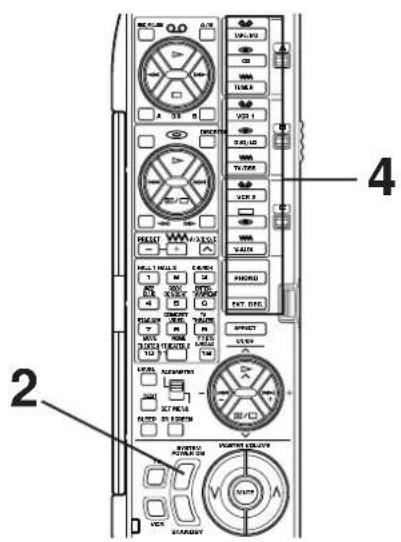
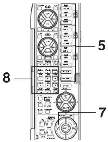
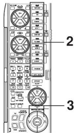
REMOTE CONTROLLER 60
Basic operation (Cover is open) 60
Using the "learning-capable" keys (Cover is open) 62
Using OPERATION CONTROL keys (Cover is closed) 64
Macro operations (Cover is closed) 66
Methods of learning and clearing functions 68
TROUBLESHOOTING 71
SPECIFICATIONS 74
CAUTION : Read this before operating your unit.
- To assure the finest performance, please read this manual carefully. Keep it in a safe place for future reference.
- Install this unit in a cool, dry, clean place - away from windows, heat sources, sources of excessive vibration, dust, moisture and cold. Avoid sources of humming (transformers, motors). To prevent fire or electrical shock, do not expose the unit to rain or water.
- Never remove the unit cover. Contact your dealer if an object falls inside the unit.
- Do not use force on switches, controls or connection wires. When moving the unit, first disconnect the power plug and the wires connected to other equipment. Never pull on the wires themselves.
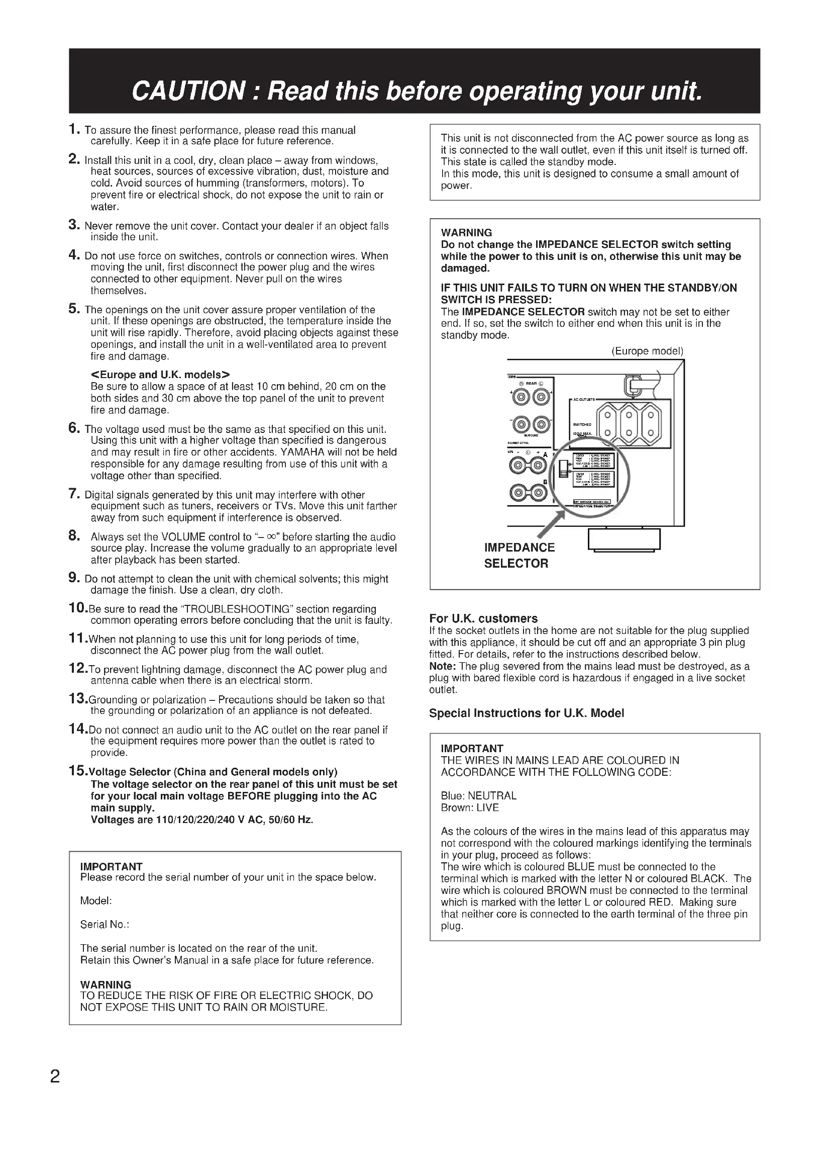
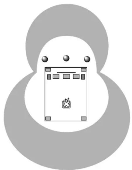
- The openings on the unit cover assure proper ventilation of the unit. If these openings are obstructed, the temperature inside the unit will rise rapidly. Therefore, avoid placing objects against these openings, and install the unit in a well-ventilated area to prevent fire and damage.
Be sure to allow a space of at least 10cm behind, 20cm on the both sides and 30cm above the top panel of the unit to prevent fire and damage.
- The voltage used must be the same as that specified on this unit. Using this unit with a higher voltage than specified is dangerous and may result in fire or other accidents. YAMAHA will not be held responsible for any damage resulting from use of this unit with a voltage other than specified.
- Digital signals generated by this unit may interfere with other equipment such as tuners, receivers or TVs. Move this unit farther away from such equipment if interference is observed.
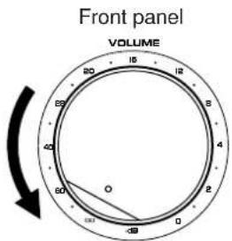
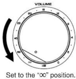
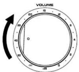
- Always set the VOLUME control to - before starting the audio source play. Increase the volume gradually to an appropriate level after playback has been started.
- Do not attempt to clean the unit with chemical solvents; this might damage the finish. Use a clean, dry cloth.
10.Be sure to read the "TROUBLESHOOTING" section regarding common operating errors before concluding that the unit is faulty. - When not planning to use this unit for long periods of time, disconnect the AC power plug from the wall outlet.
- To prevent lightning damage, disconnect the AC power plug and antenna cable when there is an electrical storm.
- Grounding or polarization - Precautions should be taken so that the grounding or polarization of an appliance is not defeated.
- Do not connect an audio unit to the AC outlet on the rear panel if the equipment requires more power than the outlet is rated to provide.
15.Voltage Selector (China and General models only) The voltage selector on the rear panel of this unit must be set for your local main voltage BEFORE plugging into the AC main supply. Voltages are 110/120/220/240 V AC, 50 / 60Hz
IMPORTANT
Please record the serial number of your unit in the space below.
Model:
Serial No.:
The serial number is located on the rear of the unit. Retain this Owner's Manual in a safe place for future reference.
WARNING
TO REDUCE THE RISK OF FIRE OR ELECTRIC SHOCK, DO NOT EXPOSE THIS UNIT TO RAIN OR MOISTURE.
This unit is not disconnected from the AC power source as long as it is connected to the wall outlet, even if this unit itself is turned off. This state is called the standby mode.
In this mode, this unit is designed to consume a small amount of power.
WARNING
Do not change the IMPEDANCE SELECTOR switch setting while the power to this unit is on, otherwise this unit may be damaged.
IF THIS UNIT FAILS TO TURN ON WHEN THE STANDBY/ON SWITCH IS PRESSED:
The IMPEDANCE SELECTOR switch may not be set to either end. If so, set the switch to either end when this unit is in the standby mode.

SELECTOR
For U.K. customers
If the socket outlets in the home are not suitable for the plug supplied with this appliance, it should be cut off and an appropriate 3 pin plug fitted. For details, refer to the instructions described below.
Note: The plug severed from the mains lead must be destroyed, as a plug with bared flexible cord is hazardous if engaged in a live socket outlet.
Special Instructions for U.K. Model
IMPORTANT
THE WIRES IN MAINS LEAD ARE COLOURED IN ACCORDANCE WITH THE FOLLOWING CODE:
Blue: NEUTRAL
Brown: LIVE
As the colours of the wires in the mains lead of this apparatus may not correspond with the coloured markings identifying the terminals in your plug, proceed as follows:
The wire which is coloured BLUE must be connected to the terminal which is marked with the letter N or coloured BLACK. The wire which is coloured BROWN must be connected to the terminal which is marked with the letter L or coloured RED. Making sure that neither core is connected to the earth terminal of the three pin plug.
Features
7 Channel Power Amplification
Main: 100W + 100W (8Ω) RMS Output Power, 0.02% THD, 20-20,000 Hz
Center: 100W (8Ω) RMS Output Power, 0.02% THD, 20-20,000 Hz
Rear: 100W + 100W (8Ω) RMS Output Power, 0.02% THD, 20-20,000 Hz
Front effect: 25W + 25W (8Ω) RMS Output Power, 0.05% THD, 1 kHz
Multi-Mode Digital Sound Field Processing
- Digital Sound Field Processor (DSP)
- Dolby Digital Decoder
- Dolby Pro Logic Surround Decoder
- DTS Decoder
CINEMA DSP: Theater-like Sound Experience by the Combination of YAMAHA DSP Technology and Dolby Digital, Dolby Pro Logic or DTS
Automatic Input Balance Control for Dolby Pro Logic Surround - Test Tone Generator for Easier Speaker Balance Adjustment
- Speaker Output Mode Selection Capability for the Most Suitable Use of Your Speaker System
Others
- “SET MENU” Mode which Provides You with 8 Titles of Setting Changes and Adjustments for Optimizing this Unit for Your Audio/Video System
- BASS EXTENSION Button for Reinforcing Bass Response
- On Screen Display Function Helpful in Controlling This Unit
REC OUT Selector which is Independent of Input Source Selection
SLEEP Timer
OPTICAL and COAXIAL Digital Audio Signal Terminals - 6 Channel External Decoder Input for Other Future Formats
Video Signal Input/Output Capability (Including S Video Connections) - Multi-Functional remote controller with "Learning" Capability
What's DSP?
Introduction
Welcome to the exciting world of digital home entertainment. This unit is one of the most complete and advanced AV amplifier available. Some of the more advanced features may not be familiar to you, but they are easy to use. State-of-the-art technologies such as Dolby Digital and Digital Theater Systems (DTS) may be new to your home, but you have probably experienced the amazing realism they bring to feature films in theaters around the world.
To make the listening experience even more enjoyable, this unit includes a number of exclusive, digitally created listening environments known as digital sound fields. Choosing a sound field program is like transporting yourself to such venues as an outdoor arena, a European church, or a cozy jazz club. Take some time now to read more about these features and enjoy the new experiences this unit brings to your home theater.
Digital Sound Field Processing
Technological advances in sound reproduction over the last 30 years have enhanced the listening experience with improved clarity, precision and power. However, something has still been missing: The atmosphere and acoustic ambiance of the public venue. Our Yamaha engineers have extensively researched the nature of sound acoustics and the way sound reflects inside a room. We sent these engineers to famous theaters and concert halls around the world to measure the acoustics of those venues with sophisticated microphones. The data they collected is used to recreate these environments in digital sound fields. Some of these digital sound fields are created using data measured directly at the original venue; others are created from combinations of data to form unique environments for specific purposes.
Of course, that only solves half of the problem. These engineers have no way of knowing the acoustics of your listening room, so we've made it possible for you to adjust the various parameters of this data to tailor each virtual venue to your taste. You can use these sound fields to enhance any source and in combination with any of the following surround sound technologies. Some are designed especially for music, and some especially for movies.
Dolby Pro Logic Surround
Dolby Pro Logic Surround has been used in movie theaters since the mid-seventies. It has also been available in home entertainment systems since the late eighties and continues to be a popular format for home theater systems. It uses four discrete channels and five speakers to reproduce realistic and dynamic sound effects: two main channels (left and right), a center channel for dialog, and a rear channel for special sound effects. The rear channel reproduces sound within a narrow frequency range.
Most video tapes and laser discs include Dolby Pro Logic Surround encoding as do many TV and cable broadcasts. The Dolby Pro Logic Surround decoder built into this unit employs a digital signal processing system that stabilizes each channel for even more accurate sound positioning than is available with standard analog processors.
Dolby Digital
Dolby Digital is the next level of Dolby Surround sound system developed for 35mm film-movies by employing low bit-rate audio coding.
Dolby Digital is a digital surround sound system that provides completely independent multi-channel audio to you. Dolby Digital provides five full range channels in what is sometimes referred to as a "3/2" configuration: three front channels (left, center and right), and two surround channels. A sixth bass-only effect channel is also provided for output of LFE (low frequency effect), or low bass effects that are independent of other channels. (This is called the "subwoofer channel" or "LFE channel".) This channel is counted as 0.1, thus giving rise to the term 5.1 channels in total.
Compared to Dolby Pro Logic that is referred to a "3/1" system (left front, center, right front and just one surround channel), Dolby Digital features two surround channels, called stereo or split surrounds, each offering the same full range fidelity as the three front channels.
By using the built-in Dolby Digital decoder, you can experience the dramatic realism and impact of Dolby Stereo Digital theater sound in your home.
Wide dynamic range of sound reproduced by the five full range channels and precise sound orientation by the digital sound processing presents listeners much excitement and realism that has never been experienced before.
Dolby Digital forms 5.1 channels as mentioned left, and moreover, it can also form fewer channels, for example 2 channel stereo and monaural. You may be able to find some 2 channel stereo and/or monaural sources encoded with Dolby Digital in the market.
Laserdisc and DVD are home audio formats that could benefit from Dolby Digital. In the near future, Dolby Digital will also be applied to DBS, CATV and HDTV. The ongoing release of Dolby Stereo Digital theatrical films now underway will provide an immediate source of Dolby Digital encoded video software.
DOLBY
DIGITAL
Manufactured under license from Dolby Laboratories Licensing Corporation. "DOLBY", "AC-3", "Pro Logic", and the double-D symbol are trademarks of Dolby Laboratories Licensing Corporation.
Copyright 1992 Dolby Laboratories, Inc. All rights reserved.
DTS Digital Surround
DTS (Digital Theater Systems) system was developed to replace analog soundtracks of movies with six discrete channels of digital soundtracks, and now, it is installed in many theaters around the world. The DTS digital playback system changed the way we experienced movies in theaters with six discrete channels of superb digital audio.
The DTS technology, through intense research and development, made it possible to deliver a similar encode/decode discrete technology to home audio surround-sound entertainment.
The DTS Digital Surround is an encode/decode system which delivers six channels of master-quality, 20-bit audio; technically 5.1 channels, which means 5 full-range (left, center, right and two surround) channels, plus a subwoofer (LFE) channel (as "0.1"). It is compatible with the 5.1 speaker configurations that are currently available for home theater systems
The DTS Digital Surround algorithm is designed to encode the six channels of 20-bit audio onto some laserdiscs, compact discs and DVDs with considerably less data-compression.
By using the DTS decoder built into this unit, you can experience the dramatic realism and impact of the DTS installed theater's high quality sound in your home.
Laserdisc, compact disc and DVD are home audio format within which DTS can represent its high quality multi-channel audio. (In addition to movies on laserdiscs, many exciting new multi-channel music recordings will also become available in the form of DTS-encoded compact discs.)
dt
Manufactured under license from Digital Theater Systems, Inc. US Pat. No. 5,451,942 and other world-wide patents issued and pending. "DTS", "DTS Digital Surround", are trademarks of Digital Theater Systems, Inc. Copyright 1996 Digital Theater Systems, Inc. All Rights Reserved.
CINEMA DSP: Dolby Surround + DSP / DTS + DSP
The Dolby Surround sound and DTS systems show their full ability in a large movie theater, because movie sounds are originally designed to be reproduced in a large movie theater that uses a multitude of speakers. Trying to create a sound environment similar to that of a movie theater in your home is difficult because of the room size, material inside the walls, the number of speakers, and so on. In other words, your listening room is very different from a movie theater.
However, Yamaha DSP technology allows you to create nearly the same sound experience as that of a large movie theater in your home by compensating for the lack of presence and dynamics in the listening room with original digital sound fields combined with Dolby Surround or DTS Digital Surround sounds.
CINEMA DSP
The YAMAHA "CINEMA DSP" logo indicates those programs that are created by the combination of YAMAHA DSP technology and Dolby Surround or DTS.
Dolby Pro Logic + 2 Digital Sound Fields
Digital sound fields are created on the presence side and the rear surround side of the Dolby Pro Logic Surround-decoded sound field respectively. They create a wide acoustic environment and emphasize surround-effect in the room, letting you feel much presence as if you were watching a movie in a popular Dolby Stereo theater.
This combination is available when the digital sound field program No. 8, 9, 10, 11 or "PRO LOGIC/Enhanced" of No. 12 is selected, and the input signal of the source is analog, PCM audio or encoded with the Dolby Digital in 2-channels.
Dolby Digital or DTS + 3 Digital Sound Fields
Digital sound fields are created on the presence side and the independent left and right surround sides of the Dolby Digital-decoded or the DTS-decoded sound field respectively. They create a wide acoustic environment and much surround effect in the room without losing high channel separation. With wide dynamic range of Dolby Digital or DTS sound, this sound field combination lets you feel as if you were watching a movie in the newest Dolby Stereo Digital theater or DTS installed theater. This is the most ideal home theater sound at the present time.
This combination is available when the digital sound field program No. 8, 9, 10, 11 or "DOLBY DIGITAL (or DTS DIGITAL SUR.)/Enhanced" of No. 12 is selected, and the input signal of the source is encoded with the Dolby Digital (except in 2-channels) or encoded with the DTS.
GETTING STARTED
Getting started
Unpacking
Carefully remove this unit and accessories from the box. You should find the unit itself and the following accessories.
Remote controller User function stickers
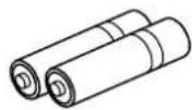
Batteries (size AA, LR6, UM-3)
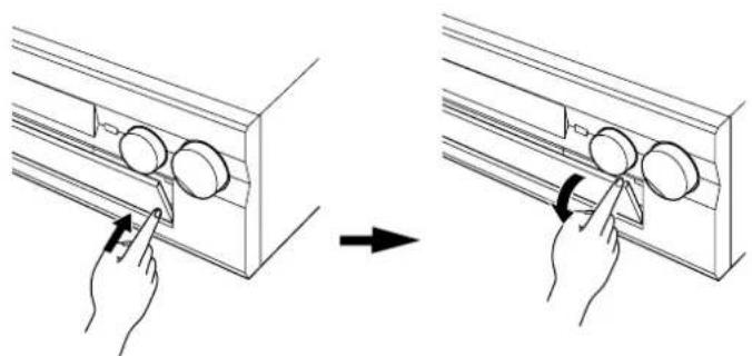
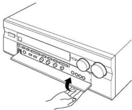
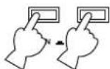
Opening and closing the front cover
Close the front cover whenever the controls inside the panel are not used.
To open the front cover
To close the front cover
Installing batteries in the remote controller
Since the remote controller will be used for many of this unit's control operations, you should begin by installing the supplied batteries.
- Turn the remote controller over and slide the battery compartment cover in the direction of the arrow.
- Insert the batteries (AA, LR6, UM-3 type) according to the polarity markings on the inside of the battery compartment.
- Close the battery compartment cover.
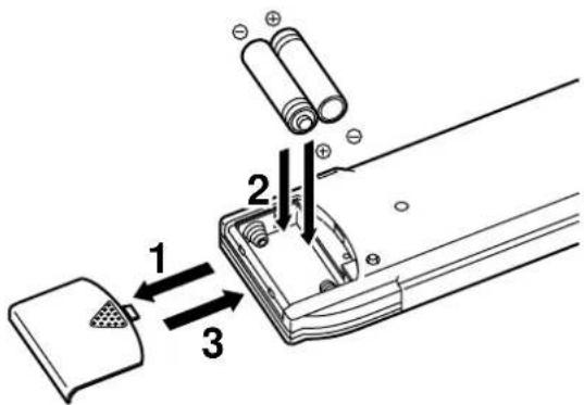
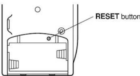
- After the batteries are inserted, press the RESET button before using the remote controller.
Notes about the remote controller
Battery replacement
If you find that the remote controller must be used closer to the main unit, the batteries are weak. Replace both batteries with new ones.
Notes
Use only AA, R6, UM-3 batteries.
(It is recommended to use an LR6 type to use the remote controller for a long period of time.)
- Be sure the polarities are correct. (See the illustration inside the battery compartment.)
- Remove the batteries if the remote controller is not used for an extended period of time.
If batteries leak, dispose of them immediately. Avoid touching the leaked material and contact with clothing, etc. Clean the battery compartment thoroughly before installing new batteries.
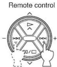
Remote controller operation range
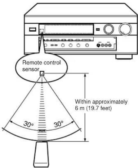
Notes
- The area between the remote controller and the main unit must be clear of large obstacles.
- Do not expose the remote control sensor to strong lighting in particular, an inverter type fluorescent lamp. Otherwise, the remote controller may not work properly. If necessary, position the main unit away from direct lighting.
Controls and their functions
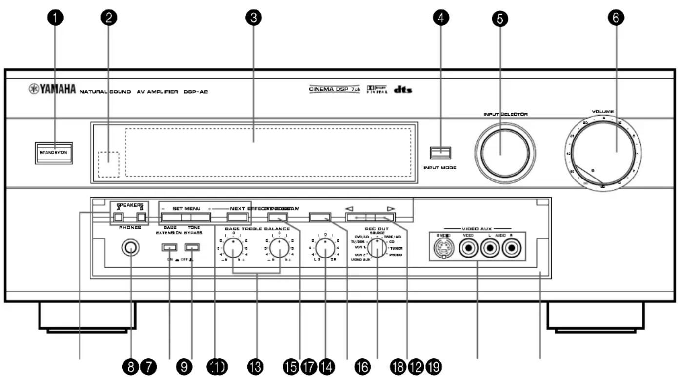
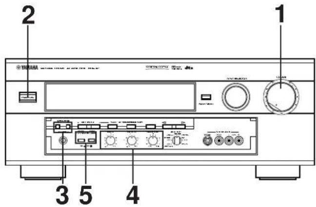
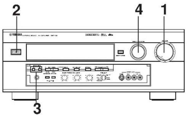
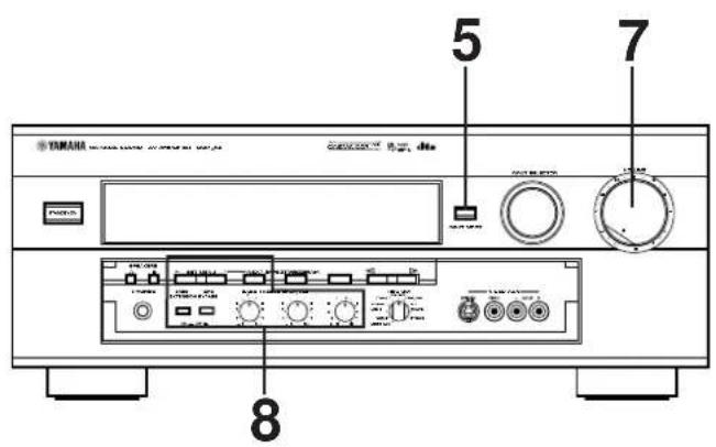
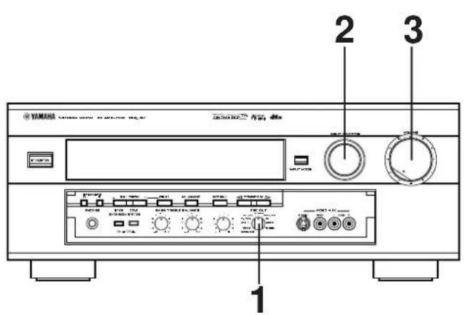
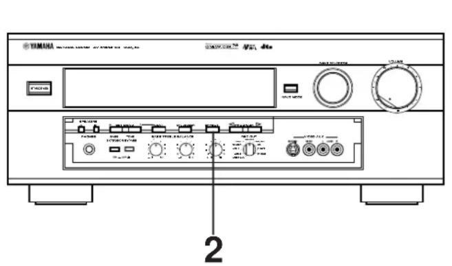
Front panel
For the remote controller, refer to pages 60 to 61.
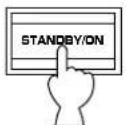
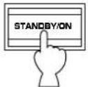
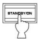
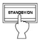
STANDBY/ON switch
Press this switch to turn on the power. Press this switch again to set this unit in the standby mode.
* A click from the switch and the initial rotation of the built-in fan will be heard when the power is turned on.
Standby mode
This unit is still using a small amount of power in this mode in order to be ready to receive infrared-signals from the remote controller.
Remote control sensor
Receives signals from the remote controller.
3 Display panel
Displays a variety of information. (Refer to page 11 for details.)
4 INPUT MODE button
Press this button to select how input signals are received from sources that output two or more types of signals. The "AUTO", "DTS" and "ANALOG" modes are available. The "AUTO", "D.D.RF", "DTS", "DGTL" and "ANALOG" modes are available for DVD/LD sources. Refer to page 35 for details.
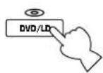
5 INPUT SELECTOR
Turn this knob to select the input source.
The selected source will be shown on the display.
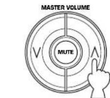
6 Master VOLUME control
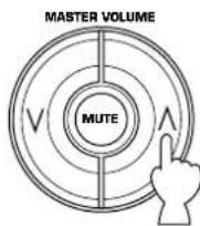
Simultaneously controls volume for all output sounds; front effect, main, rear, center and subwoofer. (The REC OUT level is not affected.)
- The indicator on the master VOLUME control will flash when the volume is decreased by pressing the MUTE key on the remote controller.
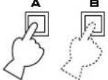
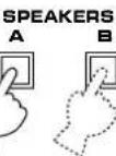
SPEAKERS switches
Press the switch A or B (or both) for the main speakers you will use to select them. Press the switch for the main speakers you will not use again to cancel them. On the display panel, "SPEAKERS A" and/or "SPEAKERS B" will be illuminated, depending on which main speakers are being selected.
8 PHONES jack
Headphones can be plugged into this jack for private listening. You can listen to the sound to be output from the main speakers through headphones. When listening with headphones privately, press both SPEAKERS A and B switches to cancel both of the main speakers A and B, and turn off the digital sound field processor by pressing the EFFECT button so that no DSP program name is illuminated on the display panel.

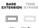
BASS EXTENSION button
Press this button inward (ON) to boost the bass frequency response at the main left and right channels while maintaining overall tonal balance. This function is effective for reinforcing the bass frequencies when a subwoofer is not used.
10 TONE BYPASS button
Press this button inward (ON) to bypass the tone (BASS and TREBLE) control circuitry. This function is used for outputting pure sound and checking the tone control settings. The tone control circuitry can be used when this button is released outward (OFF).
1 SET MENU - / + button
Press this button once or more to make a setting change or adjustment for the function selected by pressing the NEXT button.
NEXT button
Press this button once or more to select a function in the SET MENU mode.
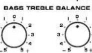
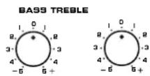
12 BASS and TREBLE controls
Rotate these knobs to adjust the low and high frequency response for the left and right main channels only.
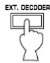
13 EXT. DECODER button
Press this button to select the input signals from the EXTERNAL DECODER INPUT terminals as the input source. This function takes priority over the INPUT SELECTOR setting. "EXT. DECODER IN" will be illuminated on the display panel. The source selected with the INPUT SELECTOR knob becomes the current input source when "EXT. DECODER IN" is not illuminated on the display panel.
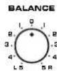
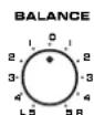
14 BALANCE control
This knob controls the sound from the main speakers only. The balance of the output volume to the left and right main speakers can be adjusted to compensate for sound imbalances caused by the speaker location or listening room conditions.
15 EFFECT button
Press this button to turn on and off the output from the center, rear and front effect speakers. The sound becomes normal 2-channel when this function is turned off.
However, this does not apply to Dolby Digital or DTS. The signals at all channels will be distributed to the main channels and output from the main speakers, even if the output from the center, rear and front effect speakers are turned off, when Dolby Digital or DTS is decoded.
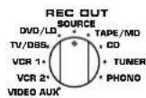
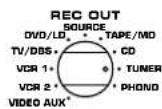
16 REC OUT selector
Rotate this knob to select the source for recording to an MD recorder (or tape deck) or VCR. This setting is independent of the INPUT SELECTOR setting, except when the REC OUT selector is set to the SOURCE position. Then the INPUT SELECTOR is used to select the source for recording to the MD recorder (or tape deck) or VCR.
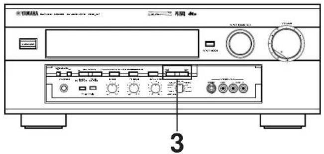
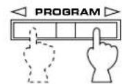
17 PROGRAM selector button
Press this button in the direction to select a digital sound field processing program.
VIDEO AUX terminals
Connect an auxiliary video or audio input source unit such as a camcorder to these terminals. A video unit with a S video output terminal can be connected to the SVIDEO terminal to obtain a high resolution picture. The source can be selected with the INPUT SELECTOR and REC OUT selector.
19 Front cover
Refer to page 7 on how to open and close the front cover.
Display panel
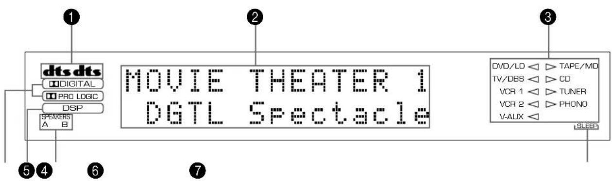
1 dtacators
Either of the "dts" indicators will be illuminated when the built-in DTS decoder is turned on.
A red "dts" indicator will be illuminated when playing a compact disc or laserdisc encoded with DTS.
An orange "dts" indicator will be illuminated when playing a DVD encoded with DTS.
An orange "dts" indicator may be illuminated when playing a laserdisc encoded with DTS after a video-CD or DVD on a DVD/LD combi-player.
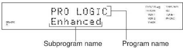
2 Multi-information display
This display shows the current DSP program and the status of adjustments and setting changes. Several statuses can be viewed at one time.
3 Input source indicators
One of the arrows for these indicators will be illuminated depending on which source is selected.
4 DIGITAL and PROLOGIC indicators
The DIGITAL indicator will be illuminated when the built-in Dolby Digital decoder is on and the signals of the source encoded with Dolby Digital are not 2-channels. The BRO LOGIC indicator will be illuminated when the built-in Dolby Pro Logic Surround Decoder is on.
DSP indicator
This indicator will be illuminated when the built-in digital sound field processor is on.
6 SPEAKERS A/B indicators
One of these indicators will be illuminated depending on which main speakers are selected. Both indicators will be illuminated when both speakers A and B are selected.
SLEEP indicator
This indicator will be illuminated when the built-in SLEEP timer is on.
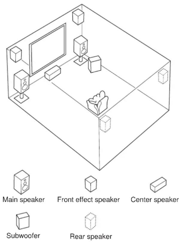
Speaker setup
Setting up your speaker system
This unit has been designed to provide the best sound field quality with a full seven-speaker system setup, using a pair of main speakers to output main source sounds, two extra pairs of effect speakers to generate the sound field plus one center speaker for dialog. We therefore recommend that you use a seven-speaker setup. A four-speaker system using only one pair of effect speakers for the sound field will still provide impressive ambience and effects, however, and may be a good way to begin with this unit. You can always upgrade to the full seven-speaker system later. In the 4 or 5 speaker system, the Digital Sound Field Processing is still performed, but the main speakers are used for both the main channels and the front effect channels.
Use of the center dialog speaker is recommended
When playing back a source with Dolby Pro Logic decoded, or playing back a source which contains center-channel signals with Dolby Digital or DTS decoded, dialog, vocals etc. are output from the center channel. Therefore, if you want to maximize the performance of your Audio/Video home theater system, it is recommended that you use a center channel speaker.
If, for some reason, it is not practical to use a center speaker, it is possible to enjoy the movie without it. Best results, however, are obtained with the full system.
Use of a subwoofer expands your sound field
It is also possible to further expand your system with the addition of a subwoofer and amplifier. The use of a subwoofer is effective not only for reinforcing bass frequencies from any or all channels, but also for reproducing signals at the subwoofer channel with high fidelity during playing back a source with Dolby Digital or DTS decoded. You may wish to choose the convenience of a Yamaha Active Servo Processing Subwoofer System, which has its own built-in power amplifier.
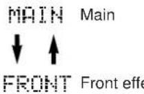
■ Speakers and speaker placement
Your full seven-speaker system will require three speaker pairs: the MAIN SPEAKERS (your normal stereo speakers), the FRONT EFFECT SPEAKERS and the REAR SPEAKERS, plus the CENTER SPEAKER. You may also be using a SUBWOOFER.
The MAIN SPEAKERS should be high performance models and have enough power handling capacity to accept the maximum output of your audio system. Other speakers do not have to be equal to the MAIN SPEAKERS. For precise sound localization, however, it is ideal to use high performance models that can reproduce sounds in full range for the CENTER SPEAKER, the FRONT EFFECT and REAR SPEAKERS.
Place the MAIN SPEAKERS in the ordinary position.
Place the FRONT EFFECT SPEAKERS further apart than the MAIN SPEAKERS, on either side of and 0.5 - 1m behind and above the MAIN SPEAKER pair.
Place the REAR SPEAKERS behind your listening position. They should be nearly 1.8m above the floor.
Place the CENTER SPEAKER precisely between the two MAIN SPEAKERS. (To avoid interference, keep the speaker above or below the television monitor, or use a magnetically shielded speaker.)
If using a SUBWOOFER, such as a Yamaha Active Servo Processing Subwoofer System, the position of the speaker is not so critical because low bass tones are not highly directional.
Recommended speaker system configurations
4 Speaker System
Basic system.
You can enjoy widely diffused sound by only adding a pair of rear speakers to a basic stereo speaker system.
1E. SYS. SETUP—Set to 5ch. (See page 27.)
1A. CENTER SP—Set to NONE. (See page 26.)
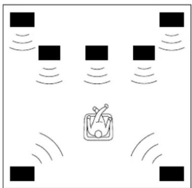
5 Speaker System
Good for Audio/Video sources.
By the use of a center speaker, center sounds (dialog, vocals etc.) are precisely localized.
1E. SYS. SETUP—Set to 5ch. (See page 27.)
1A. CENTER SP—Set to LRG or SML. (See page 26.)
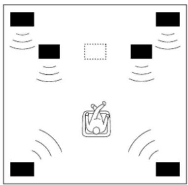
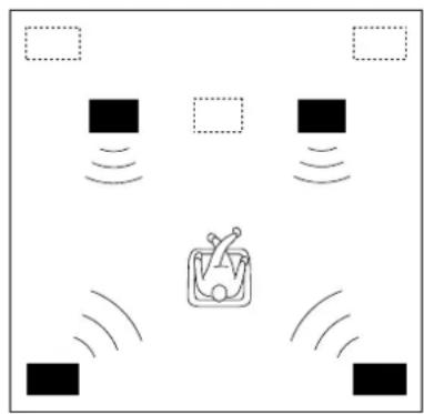
6 Speaker System
Good for sound fields from 2-channel stereo sources.
When a normal stereo source is played back with the sound field programs No. 1 through No. 7, a sound effect matching that of a 7-speaker system can be obtained. The addition of front left and right effect speakers produces a more effective sound field.
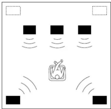
7 Speaker System
This is the recommended speaker system, providing the best sound effects.
The rear speakers and the front effect speakers produces a 360-degree sound field, and the center speaker provides precise center localization.
You can experience the amazing YAMAHA "CINEMA DSP" sound fields completely with the 7 speaker system.
1E. SYS. SETUP—Set to 7ch. (See page 27.)
1A. CENTER SP—Set to NONE. (See page 26.)
1E. SYS. SETUP—Set to 7ch. (See page 27.)
1A. CENTER SP—Set to LRG or SML. (See page 26.)
Connections
Caution: Plug in this unit and other components after all connections are completed.
All connections must be correct, that is to say L (left) to L, R (right) to R, ^+ to ^+ and - to - . Also refer to the owner's manual for each of your components.
Audio/video source equipment
- Use RCA type pin plug cables for audio/video units with the exception described later.
- The output (or input) terminals of YAMAHA audio/video units numbered as 1,2,3,4 , etc. on the rear panel must be connected to the same-numbered terminals of this unit.
Basic connections of audio units
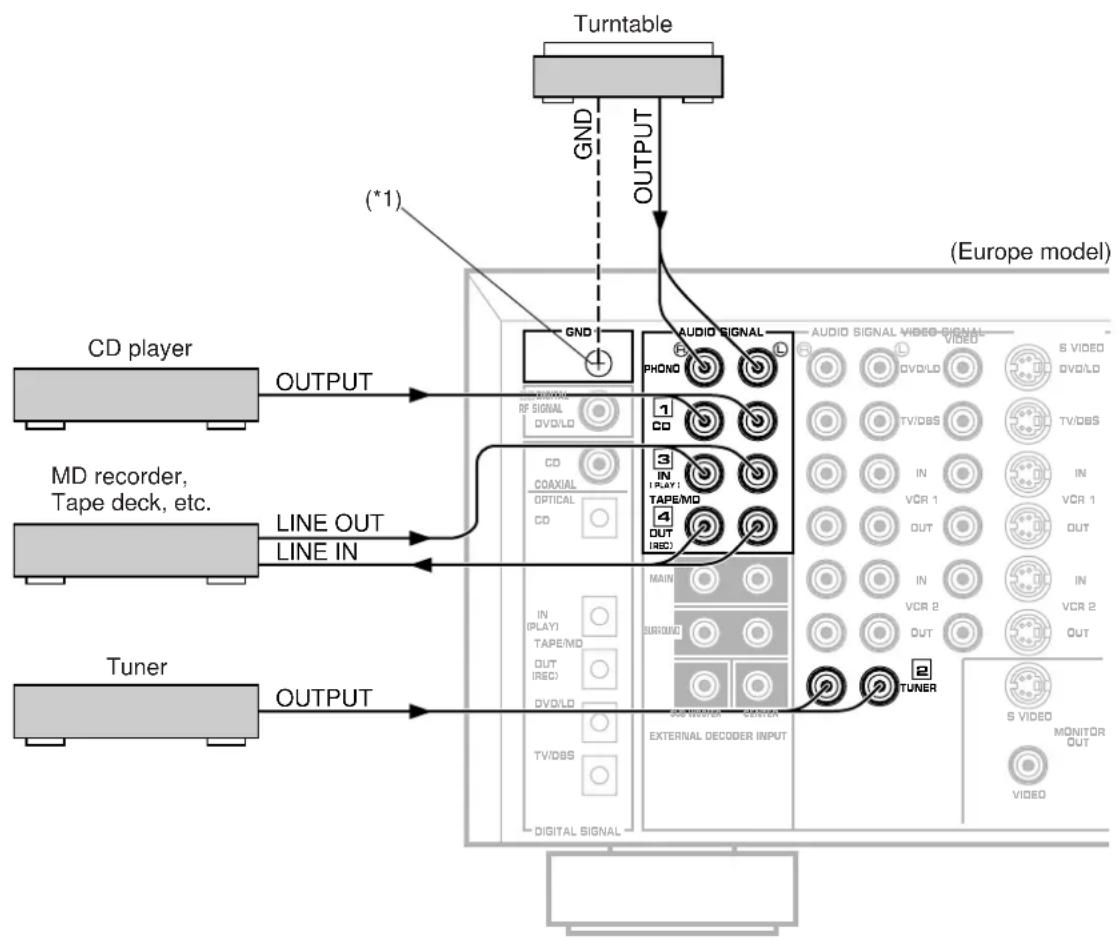
(^*1) : GND terminal (For turntable use)
Connecting the ground wire of the turntable to the GND terminal will normally minimize hum, but in some cases better results may be obtained with the ground wire disconnected.
Indicates the direction of signals.
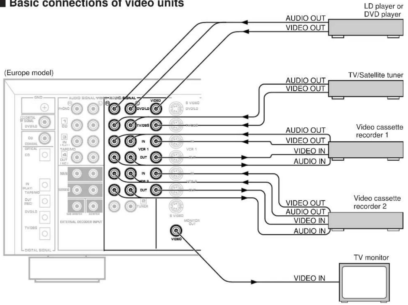
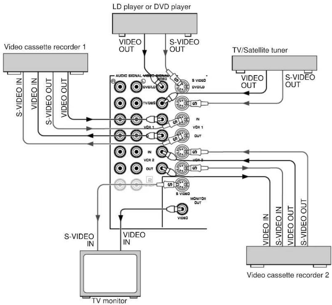
Basic connections of video units
VIDEO AUX terminals (on the front panel)
These terminals are used to connect a video input source such as a camcorder.
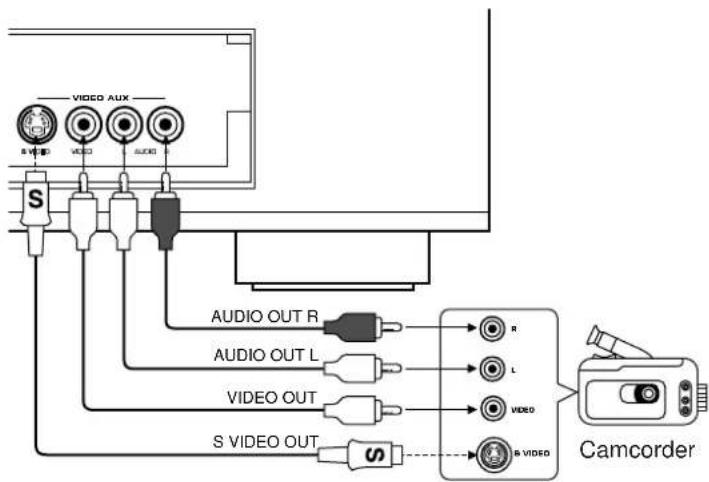

: S-video cable (Refer to page 19 for details about the SVIDEO terminal.)
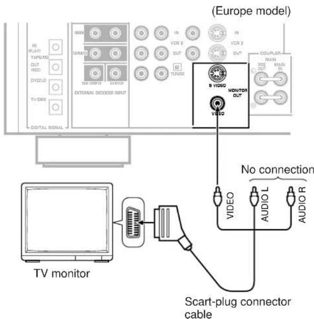
For connecting with a TV monitor that uses a 21 pin connector for input (Europe and U.K. models only)
Make a connection as figured below with a commercially available scart-plug connector cable.
PAL/NTSC switch (China and General models only)
This unit is designed for use with the NTSC and PAL television formats. Set this switch to the position for the format your TV monitor employs.

PAL: Set to this position if your TV monitor employs the PAL format.
- Outputs signals in the PAL format no matter which format (PAL or NTSC) of video signal is sent from an external video unit to this unit.
NTSC: Set to this position if your TV monitor employs the NTSC format.
- Outputs signals in the NTSC format no matter which format (PAL or NTSC) of video signal is sent from an external video unit to this unit.
Note
Be sure to input a video signal which employs the same format that your TV monitor employs, otherwise a picture will not be played back normally.
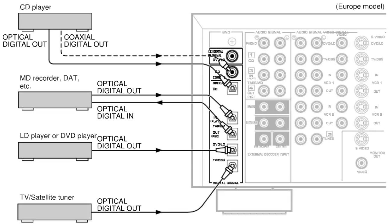
Connecting to digital (OPTICAL and COAXIAL) terminals
If your CD player, MD recorder, LD player, DVD player, TV/satellite tuner, etc. are equipped with coaxial or optical digital audio signal output terminals, they can be connected to this unit's COAXIAL or OPTICAL, or both terminals.
Digital audio signals are transmitted with less loss than analog audio signals. In addition, digital audio signal connections are necessary, especially for an LD player, a DVD player or a CD player to send signals encoded with Dolby Digital or DTS to this unit.
To make an optical digital connection between this unit and an external unit, remove the cover from each optical terminal, and then connect them by using a commercially available optical fiber cable that conforms to EIAJ standards. Other cables might not function correctly.
Even if you connect an audio/video unit to the OPTICAL (or COAXIAL) terminal of this unit, you must keep the unit connected with the same named analog audio signal terminals of this unit, because digital signal cannot be recorded by a tape deck or VCR connected to only analog audio signal terminals of this unit. You can switch the selection of input signals between "digital" and "analog" easily. (See page 35 for details.)
- However, if you connect an MD recorder or DAT to this unit's OPTICAL TAPE/MD IN and OUT terminals, it can record input sources connected to this unit's OPTICAL digital signal input terminals.
Notes
- When you connect an audio/video unit to both of the digital and analog terminals of this unit, make sure to connect to both terminals of the same name.
- Be sure to attach the covers when the OPTICAL terminals are not being used, in order to protect the terminals from dust.
In order to make this unit perform successful DTS-decoding, the DTS bitstream must not be altered, manipulated or corrupted in the process of sending the DTS bitstream from the DIGITAL OUT terminal of an external unit to a digital signal input terminal of this unit. - All digital audio signal input terminals are applicable to the sampling frequency of 32kHz , 44.1kHz and 48kHz .

: Optical fiber cable

: Coaxial cable
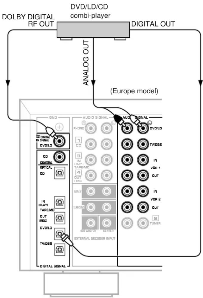
Connecting to DOLBY DIGITAL RF output of the DVD/LD/CD combi-player
If your DVD/LD/CD combi-player has a DOLBY DIGITAL RF signal output terminal, connect it to this unit's DIGITAL RF SIGNAL input terminal. Audio signals of an LD source encoded with the Dolby Digital are input to this unit by this connection. * To play back an LD source with the Dolby Digital decoded, set the input mode of DVD/LD to "AUTO" or "D.D.RF". (Refer to page 35 for details.)
It is also necessary to connect the DVD/LD/CD combi-player to this unit's analog audio signal input terminals regardless of the DOLBY DIGITAL RF signal connection. This is for playing back a source with Dolby Pro Logic Surround decoded or in normal stereo (or monaural).
You must also connect the optical digital signal output terminal of the DVD/LD/CD combi-player to the OPTICAL DVD/LD digital signal input terminal of this unit. This connection is necessary for playing back a DVD source with Dolby Digital or DTS decoded, and playing back an LD source with DTS decoded.
Note
DOLBY DIGITAL RF audio input signal cannot be recorded by a tape deck, MD recorder or VCR. To record a source played back on the DVD/LD/CD combi-player, it must be connected to the OPTICAL digital audio signal input terminal and analog audio signal input terminals of this unit.
Connecting to SVIDEO terminals
If your video cassette recorder, LD player, etc. and your monitor are equipped with "S" video terminals, connect them to this unit's SVIDEO terminals, and connect this unit's SVIDEO MONITOR OUT terminal to the "S" video input of your monitor. With this connection, you can play back and record high quality pictures. Otherwise, connect the "composite" video terminals from your video cassette recorder, LD player, etc. to theVIDEO terminals of this unit, and connect this unit'sVIDEO MONITOR OUT terminal to the "composite" video input of your monitor.
Note
If video signals are sent to both SVIDEO input andVIDEO input terminals, the signals will be sent to their respective output terminals.
Notes about the Video superimpose
- If you watch a video source that is connected to both SVIDEO and VIDEO input terminals of this unit, signals of screen display information are output from only the SVIDEO MONITOR OUT terminal.
- When no video signal is input to either SVIDEO or VIDEO input terminals of this unit, signals of screen display information are output from both SVIDEO MONITOR OUT and VIDEO MONITOR OUT terminals with a color background.
- For China and General models, if the PAL/NTSC switch on the rear panel is set to "PAL", nothing will be output from either SVIDEO MONITOR OUT orVIDEO MONITOR OUT terminal in this case.
SVIDEO terminals
This unit provides you with SVIDEO terminals in addition to standard typeVIDEO terminals.
SVIDEO terminals transmit video signals separated into luminance (Y) signals and color (C) signals. In comparison with SVIDEO terminals, standard typeVIDEO terminals transmit "composite" video signals.
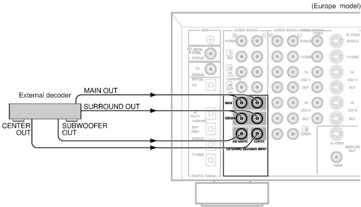
- Connecting an external decoder of a future format to this unit
This unit is equipped with additional 6-channel audio signal input terminals (for left main, right main, center, left rear surround, right rear surround and subwoofer channels) for inputting signals from an external decoder of a future format to this unit.
To listen to a sound by reproducing signals input to these terminals, press the EXT. DECODER button on the front panel so that "EXT. DECODER IN" appears on the display. By doing so, the signals input to these terminals are sent to the corresponding SPEAKERS terminals and OUTPUT terminals of this unit.
- When signals input to these terminals are selected, the digital sound field processor cannot be used.
- The settings of "1A" to "1E" in the SET MENU mode have no effect on the signals input to these terminals. The setting of "1F. MAIN LEVEL" is effective. (Refer to pages 26 to 27 for details.)
- The adjustments of the output level of the center speaker, rear speakers and subwoofer are effective when the signals input to these terminals are selected as the input source. (Refer to pages 43 to 44 for details.)
Speakers
Use speakers with the specified impedance shown on the rear of this unit.
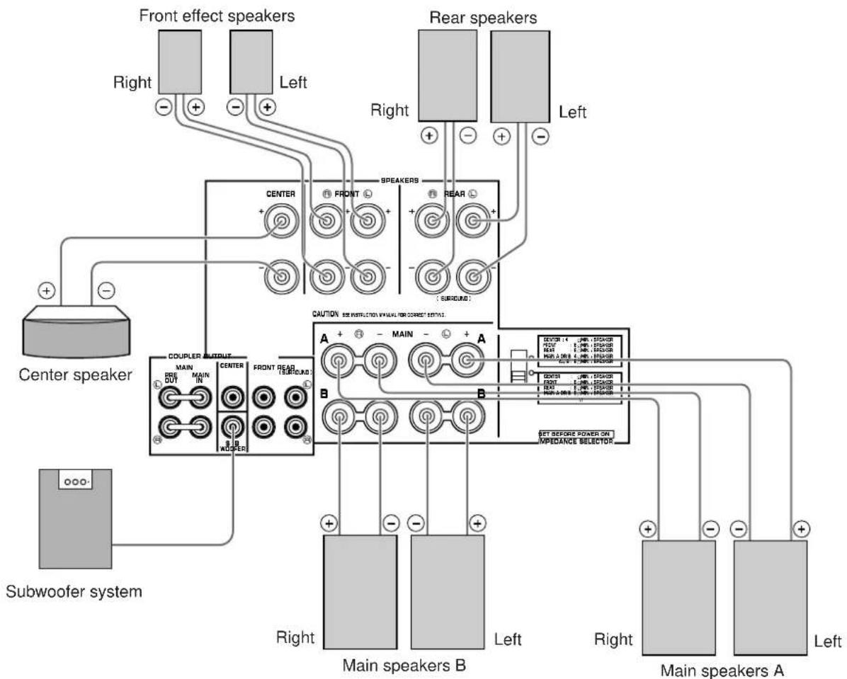
How to Connect:
Connect the SPEAKERS terminals to your speakers with the wire of the proper gauge (keep as short as possible). If the connections are faulty, no sound will be heard from the speakers. Make sure that the polarity of the speaker wires is correct. That is the + and - markings are observed. If these wires are reversed, the sound will be unnatural and lack bass.
Caution
Do not let the bare speaker wires touch each other or any metal part of this unit. This could damage this unit or the speakers, or both.
Red: positive (+)
Black: negative (-)
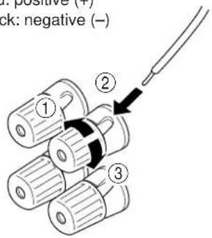
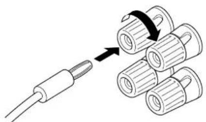
① Loosen the knob.
② Insert the bare wire. [Remove approx. 5mm (1/4") insulation from the speaker wires.]
③ Tighten the knob and secure the wire.
Banana Plug connections are also possible. Simply insert the Banana Plug connector into the corresponding terminal.
Note on main speaker connections:
One or two speaker systems can be connected to this unit. If you use only one speaker system, connect it to either the SPEAKERS A or B terminals.
Note on a subwoofer connection:
You may wish to add a subwoofer to reinforce low frequencies or to output low bass sound from the subwoofer channel when reproducing discrete signals.
When using a subwoofer, connect the SUBWOOFER terminal of this unit to the INPUT terminal of the subwoofer amplifier, and connect the speaker terminals of the subwoofer amplifier to the subwoofer.
With some subwoofoers, including the Yamaha Active Servo Processing Subwoofer System, the amplifier and subwoofer are in the same unit. Such a subwoofer needs only the connection between the SUBWOOFER terminal of this unit and the INPUT terminal of the subwoofer.
(Refer to page 23 for details about the SUBWOOFER terminal.)
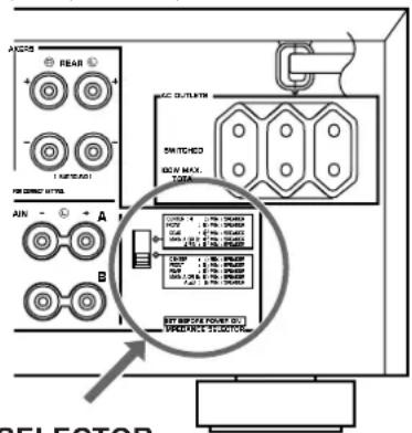
■ IMPEDANCE SELECTOR switch
WARNING
Do not change the IMPEDANCE SELECTOR switch setting while the power to this unit is on, otherwise this unit may be damaged.
IF THIS UNIT FAILS TO TURN ON WHEN THE STANDBY/ON SWITCH IS PRESSED:
The IMPEDANCE SELECTOR switch may not be set to either end. If so, set the switch to either end when this unit is in the standby mode.
(Europe model)
IMPEDANCE SELECTOR
Select the position whose requirements your speaker system meets.

(Upper position)
Center: The impedance of the speaker must be 4 or higher.
Front effect:
The impedance of each speaker must be 6 or higher.
Rear: The impedance of each speaker must be 6 or higher.
Main: If you use one pair of main speakers, the impedance of each speaker must be 4 or higher. If you use two pairs of main speakers, the impedance of each speaker must be 8 or higher.

(Lower position)
Center: The impedance of the speaker must be 8 or higher.
Front effect:
The impedance of each speaker must be 8 or higher.
Rear: The impedance of each speaker must be 8 or higher.
Main: If you use one pair of main speakers, the impedance of each speaker must be 8Ω or higher. If you use two pairs of main speakers, the impedance of each speaker must be 16Ω or higher.
To drive main, center, front effect and/or rear speakers with external amplifiers
The speaker connections described on page 21 are fine for most applications. If for some reason, however, you wish to drive main, center, front effect and/or rear speakers with your existing amplifier, etc., the following terminals are available for connecting external amplifier(s) to this unit.
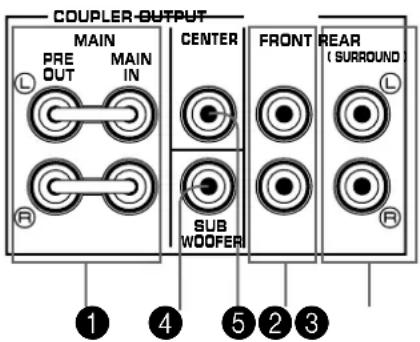
1 MAIN PRE OUT/MAIN IN terminals
The PRE OUT terminals are for main channel line output, and the MAIN IN terminals are for line input to the built-in main channel amplifier. The PRE OUT and MAIN IN terminals must be connected with jumper bars when the built-in amplifier is used.
However, if you drive main speakers with an external stereo power amplifier, first remove the jumper bars, and then connect the input terminals of the external amplifier (MAIN IN or AUX terminals of an amplifier or a receiver) to the PRE OUT terminals. No connection is needed to the MAIN IN terminals.
- Output signals from the PRE OUT terminals are affected by the use of BASS, TREBLE, BALANCE controls and BASS EXTENSION button and the TONE BYPASS button.
SUBWOOFER terminal
When using a subwoofer, connect its amplifier input to this terminal. Low frequencies distributed from the main, center and/or rear channels are output from this terminal. (The cut-off frequency of this terminal is 90Hz .) Signals of LFE (low frequency effect) generated when Dolby Digital or DTS is decoded are also output if they are assigned to this terminal.
3 CENTER terminal
This terminal is for center channel line output.
If you drive a center speaker with an external power amplifier, connect the input terminal of the external amplifier to this terminal.
There is no connection to this terminal when you use the built-in amplifier.
4 FRONT terminals
These terminals are for front effect channel line output. If you drive front effect speakers with an external stereo power amplifier, connect the input terminals of the external amplifier (MAIN IN or AUX terminals of an amplifier or a receiver) to these terminals.
There is no connection to these terminals when you use the built-in amplifier.
REAR (SURROUND) terminals
These terminals are for rear channel line output.
If you drive rear speakers with an external stereo power amplifier, connect the input terminals of the external amplifier (MAIN IN or AUX terminals of an amplifier or a receiver) to these terminals.
There is no connection to these terminals when you use the built-in amplifier.
Notes
Output level of signals from all of these terminals are adjusted by the use of VOLUME control on the front panel or MASTER VOLUME keys on the remote controller.
If an external power amplifier is connected to the CENTER, FRONT or REAR output terminals, do not use the corresponding SPEAKERS terminals (CENTER, FRONT or REAR).
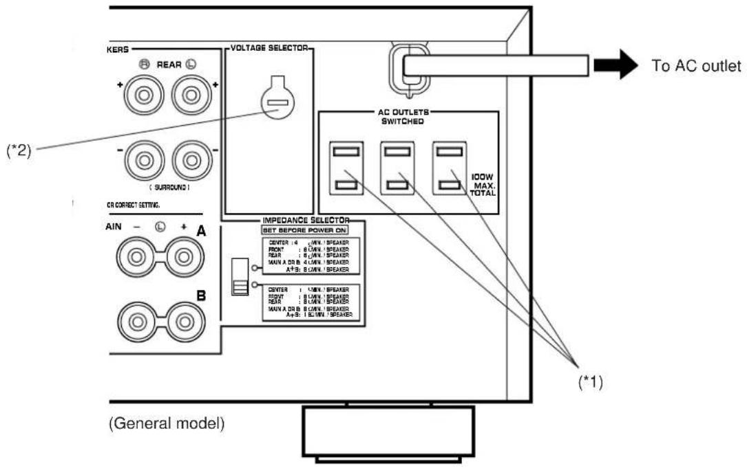
Plugging in this unit
-
After completing all connections, plug the AC power cord into an AC outlet.
-
Unplug the AC power cord from the AC outlet if this unit is not to be used for a long period of time.
(^1) (^2)
AC OUTLET(S)
(Europe, China and General models) 3 SWITCHED OUTLETS (U.K. model) 1 SWITCHED OUTLET
Use these to connect the power cords of your components to this unit.
The power to the SWITCHED outlets is controlled by this unit's STANDBY/ON switch or the remote controller's SYSTEM POWER ON and STANDBY keys. These outlets will supply power to any connected unit whenever this unit is turned on. The maximum power (total power consumption of components) that can be connected to the SWITCHED AC OUTLET(S) is 100W.
Voltage Selector (China and General models only)
The voltage selector on the rear panel of this unit must be set for your local main voltage BEFORE plugging into the AC main supply.
Voltages are 110/120/220/240 V AC, 50/60 Hz.
On screen display
If you connect your VCR, LD player, video monitor, etc. to this unit, you can take advantage of this unit's capability to display program titles, parameter data and information for various setting changes and adjustments on your video monitor screen. This information will be superimposed over the video image.
If there is no video source connected or it is turned off, the information will be displayed over a blue colored background.
Note: The program titles, parameter data and other information are also displayed on the display panel of this unit.
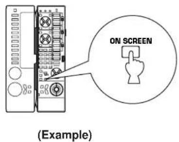
Selecting a type of display
You can change the type of display showing various information on the monitor screen by pressing the ON SCREEN display key on the remote controller.
Press this key to change the screen to a full or simple display, or no display at all.
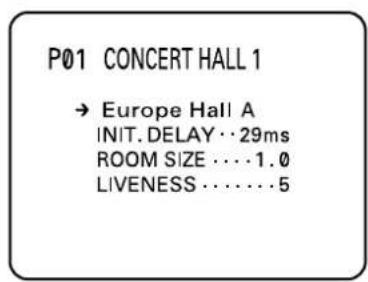
Full display
P01 CONCERT HALL 1
Europe Hall A
INIT.DELAY·29ms
ROOM SIZE···1.0
LIVENESS···5
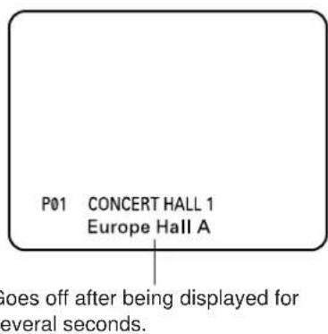
Simple display
Notes
- When making a setting change or adjustment in the SET MENU mode, or adjusting the speaker balance by using the test tone, information is fully displayed on the monitor screen even if another type of display is currently selected.
Information displayed on the monitor screen in this way cannot be recorded by a VCR.
Selecting the output modes ("SET MENU" mode)
The following functions control the output signals to the speakers in your audio system. When speaker connections are all completed, select a proper position on each function to maximize the performance of your speaker system.
- For details about the SET MENU mode, refer to pages 50 to 53.
1. SPEAKER SET
1A. CENTER SP
1B. REAR SP
1C. MAIN SP
1D. LFE/BASS OUT
1E. SYS. SETUP
1F. MAIN LEVEL
Function description
1A. CENTER SP
Choices: LARGE (LRG)/SMALL (SML)/NONE Preset position: LRG
LRG: When your center speaker is approximately the same size as the main speakers.
SML: When you use a center speaker that is smaller than the main speakers. In this position, low bass signals (below 90Hz ) at the center channel are output from the SUBWOOFER terminals (or the main speakers if the MAIN position is selected on "1D. LFE/BASS OUT").
NONE: When you do not have a center speaker. The center channel sound will be output from the left and right main speakers.
1B. REAR SP
Choices: LARGE/SMALL Preset position: LARGE
LARGE: If your rear speakers have a high ability for bass reproduction, or a subwoofer is connected to the rear speaker in parallel. In this position, full range signals are output from the rear speakers.
SMALL: If your rear speakers do not have a high ability for bass reproduction. In this position, low bass signals (below 90Hz ) at the rear channels are output from the SUBWOOFER terminals (or the main speakers if the MAIN position is selected on "1D. LFE/BASS OUT").
1C. MAIN SP
Choices: LARGE/SMALL Preset position: LARGE
LARGE: If your main speakers have a high ability for bass reproduction. In this position, full range signals present at the main channels are output from the main speakers.
SMALL: If your main speakers do not have a high ability for bass reproduction. However, if your system does not include a subwoofer, do not select this position. In this position, low bass signals (below 90Hz ) at the main channels are output from the SUBWOOFER terminals (if the SW or BOTH position is selected on "1D. LFE/BASS OUT").
1D. LFE/BASS OUT
Choices: SW/MAIN/BOTH Preset position: SW
MAIN: If your system does not include a subwoofer. In this position, full range signals present at the main channels, signals from the LFE channel and other low bass signals that are selected on "1A. CENTER SP" to "1C. MAIN SP" to be distributed from other channels are output from the main speakers.
SW/BOTH:
Select either the SW or BOTH position if your system includes a subwoofer.
In either position, signals at LFE channel and other low bass signals that are selected on "1A. CENTER SP" to "1C. MAIN SP" to be distributed from other channels are output from the SUBWOOFER terminals.
When the LARGE position is selected on "1C. MAIN SP", in the SW position, no signal is distributed from the main channels to the SUBWOOFER terminals, however in the BOTH position, low bass signals from the main channels are output to both of the main speakers and the SUBWOOFER terminals.
1E. SYS. SETUP
Choices: 7ch/5ch
Preset position: 7ch
7ch: If your speaker system includes a pair of front effect speakers.
5ch: If your speaker system does not include a pair of front effect speakers. Sound signals at the left and right front effect channels are distributed to the left and right main channels respectively, and output from the main speakers.
1F. MAIN LEVEL
Choices: Normal/-10dB Preset position: Normal
Normal: Normally, select this position.
-10dB: If the volume levels to the center, rear and/or front effect speakers are lower than the level to the main speakers even though they are adjusted to maximum. The volume level to the main speakers are decreased by 10 dB, so you can adjust the speaker output level balance properly.
Note
The settings of "1A" to "1E" have no effect on the signals input to the EXTERNAL DECODER INPUT terminals on the rear of this unit.
Changing selections
Refer to the display panel or the monitor screen when changing the selections.

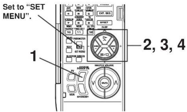
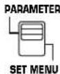
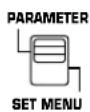
When using the remote controller, set the PARAMETER /SET MENU switch to the SET MENU position.
Note: The cover of the remote controller must be open.

Remote control
PARAMETER
SET MENU
1 Turn on the power of this unit. (If necessary, turn on the power of the monitor to display information.)
Front panel

Remote control
SYSTEM
POWER ON
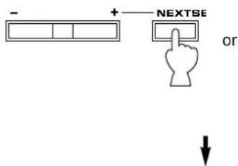
2 Select the function "1. SPEAKER SET" by pressing one of the following buttons once or more. (The title will appear on the display).
Front panel
Remote control
- SPEAKER SET
Press +/Key!
10/101
912
与产
3 Front panel Remote control
Press once.
1A. CENTER SP
PLRG SNL NO
W7.48 25 W11 100
V12 P000
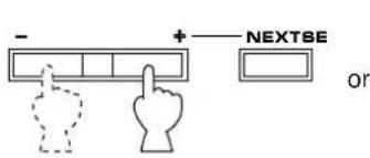
4 Press ^ 十 + ^ 一 or - once or more to position the arrow-shaped cursor at the desired selection.
Front panel
Remote control

Cursor
1A. CENTER SP
LRG SML NONE
V
2014年/12月3日
5 Follow the same procedure for "1B. REAR SP", "1C. MAIN SP", "1D. LFE/BASS OUT", "1E. SYS. SETUP" and/or "1F. MAIN LEVEL".
First select the function by following step 2, and then select the proper position by following step 4.
Speaker balance adjustment
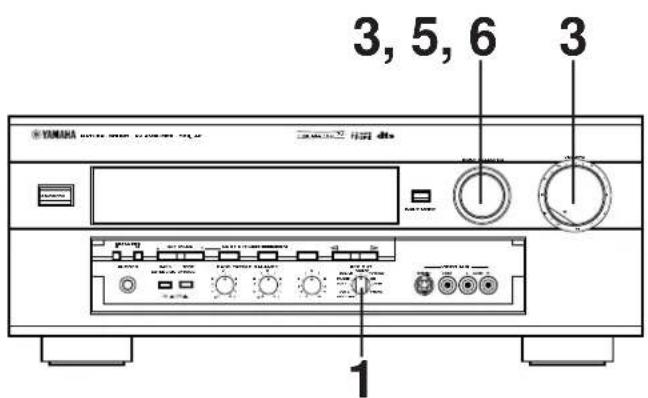
This procedure lets you adjust the sound output level balance between the main, center, rear and front effect speakers using the built-in test tone generator. After the adjustments, the sound output level heard at the listening position will be the same from each speaker. This is important for the best performance of the digital sound field processor, the Dolby Digital decoder, the Dolby Pro Logic Surround decoder and the DTS decoder.
The adjustment of each speaker output level should be done at your listening position with the remote controller. Note: The cover of the remote controller must be open.
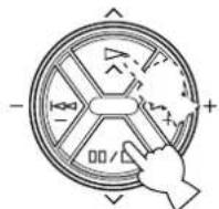
1
Set to the "oo" position.
2 Turn on the power.
Front panel

Remote control
SYSTEM POWER ON
3 Select main speakers A or B. The corresponding indicator will be illuminated.
Front panel
SPEAKERS
* Both speakers A and B can be selected.
4
Front panel

Set to the "0" position.
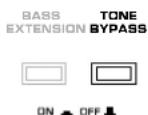
5
Front panel
BASS TONE EXTENSION BYPASS
Set to the "OFF (
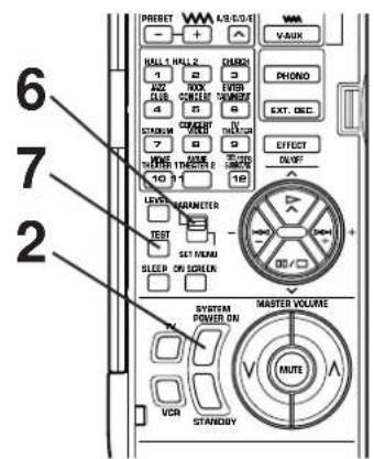
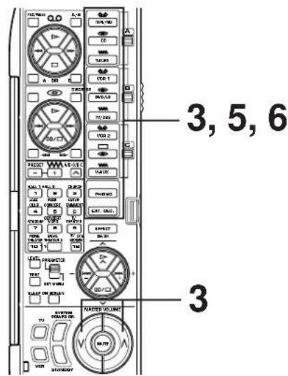
6 Set the PARAMETER/SET MENU switch on the remote controller to the PARAMETER position.
Remote control
7 Press the TEST key on the remote controller so that "TEST DOLBY SUR." appears on the display to enter the test mode.

Remote control

TEST DOLBY SUR. LEFT
CONTINUED
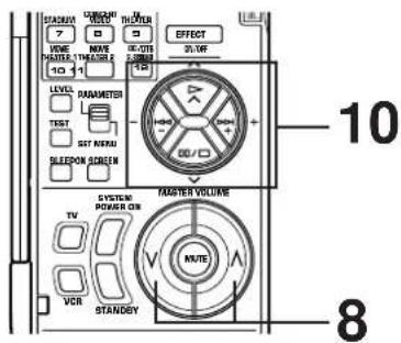
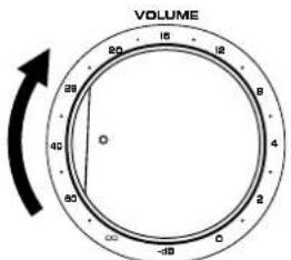
8 Turn up the volume.
Remote control
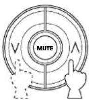
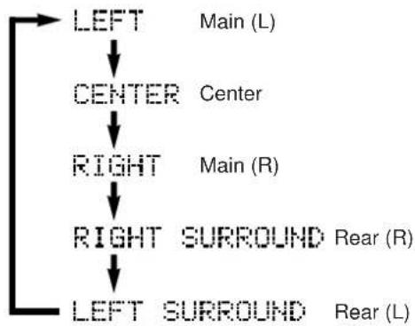
You will hear a test tone (like pink noise) from the left main speaker, then the center speaker, then the right main speaker, then the right rear speaker, and then the left rear speaker, for about 2.5 seconds each. The display changes as shown below.
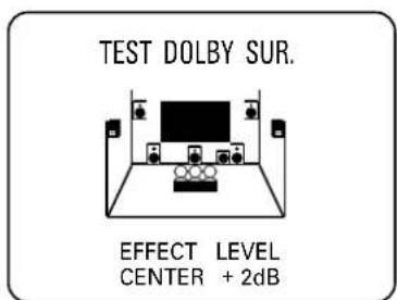
- The state of the test tone output is also shown on the monitor screen by an image of the audio listening room. This is convenient for adjusting each speaker level.
- If the function "1A. CENTER SP" in the SET MENU mode is set in the "NONE" position, you will hear the center channel test tone from the left and right main speakers.
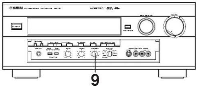
9 Adjust the BALANCE control so that the effect sound output level of the left main speaker and the right main speaker are the same.
Front panel
10 Adjust the sound output levels of the center speaker and the rear speakers so that they become almost the same as the main speakers.
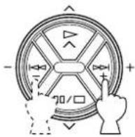
How to adjust:
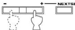
Pressing the + or - key adjusts the level to the speaker (except the main speakers) currently outputting the test tone.
- Pressing the + key raises and the - key lowers the level.
- While adjusting, the test tone is fixed on the selected speaker.
Remote control
If desired, you can select a speaker to output the test tone by pressing the or key once or more so that "CENTER", "RIGHT SURROUND" or "LEFT SURROUND" appears on the display.
- While holding the or key pressed, the test tone is fixed on the selected speaker.
- "CENTER" shows the center speaker is selected, "RIGHT SURROUND" shows the right rear speaker, and "LEFT SURROUND" shows the left rear speaker.
- The output level of the selected speaker can be adjusted by the + or - key.
Remote control
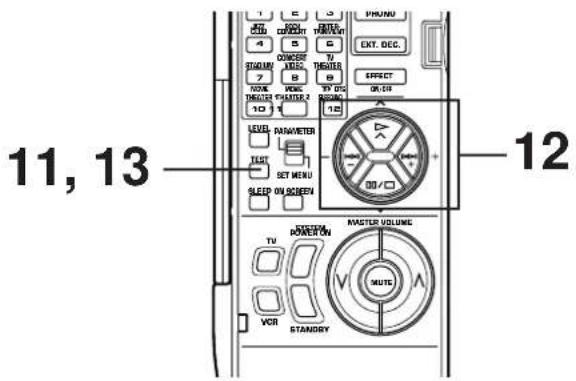
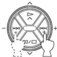
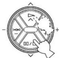
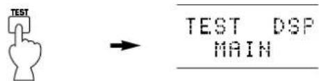
11 For the front effect speaker level adjustment, press the TEST key on the remote controller again so that "TEST DSP" appears on the display.
Remote control
A calibration signal should be heard from the main speakers and the front effect speakers in turn.
12 Adjust the front effect speaker level by pressing the + or - key so that it becomes almost the same as the main speakers.
- While adjusting, the test tone is fixed on the front effect speaker.
- Pressing the or key makes the test tone fix on the left front effect speaker and the right front effect speaker respectively. This is helpful for you to check that each speaker is correctly connected to this unit.
13 When the adjustment is finished, press the TEST key once again to cancel the test tone.
Remote control

Notes
Once you have completed these adjustments, you can adjust the sound level on your audio system by using the VOLUME control (or the MASTER VOLUME keys on the remote controller) only.
- If you use external power amplifiers, you may also use their volume controls to obtain proper balance.
- If the function "1A. CENTER SP" in the SET MENU mode is set in the "NONE" position, in step 10, the sound output level of the center speaker cannot be adjusted. This is because in this mode, the center sound is automatically output from the left and right main speakers.
- If there is insufficient sound output from the center and rear speakers, you may decrease the main speaker output level by setting the function "1F. MAIN LEVEL" in the SET MENU mode in the "-10dB" position.
BASIC OPERATION
Playing a source
1
Front panel
2 Turn on the power.
Front panel

Remote control
or
SYSTEM POWER ON
3 Select main speakers A or B. The corresponding indicator will be illuminated.
Front panel
* Both speakers A and B can be selected.
4
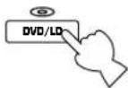
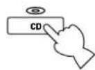
Select an input source.
(For video sources, turn on the TV/monitor.) The selected source is shown on the display panel and the monitor screen.

Front panel
Remote control

Name of the selected input source
To select the source connected to the EXTERNAL DECODER INPUT terminals, press the EXT. DECODER button. "EXT. DECODER IN" will be illuminated on the display. (Refer to page 34 for details.)
CONTINUED
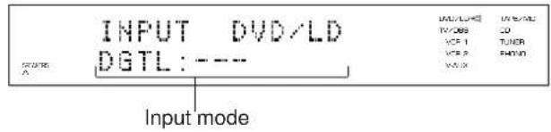
5
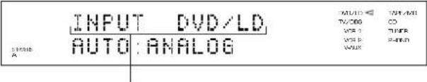
The current input mode is also shown for a source that inputs two or more types of signals to this unit.
To change the input mode, press the INPUT MODE button on the front panel or the input selector key for the currently selected source on the remote controller. (Refer to page 35 for details on switching the input mode.)
Front panel
Remote control
or

6
Play the source.
7
Front panel
Remote control
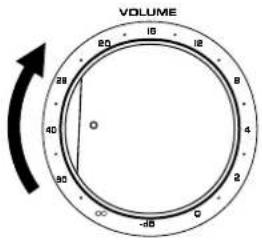
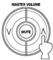
Adjust the output level.
8
Adjust the BASS, TREBLE, BALANCE controls, etc. (refer to page 39) and use the digital sound field processor. (Refer to pages 40-42.)
When you finish using this unit
Press the STANDBY/ON switch on the front panel or the STANDBY key on the remote controller to enter the standby mode.
Front panel
Remote control
or

To select the source connected to this unit's EXTERNAL DECODER INPUT terminals as the input source.
Press the EXT. DECODER button. "EXT. DECODER IN" will appear on the display.
Front panel
Remote control
or

EXT. DECODER IN
Note
The input source selected in this way has priority over any other input source already selected.
To select another input source, press the EXT. DECODER button again so that "EXT. DECODER IN" goes off from the display, and then use the INPUT SELECTOR.
Notes on input source selection
Note that selecting an input source means that the source which is connected to the corresponding input terminals on the rear panel is selected.
* To select the source connected to theVIDEO AUX terminals on the front panel, select "V-AUX".
- The setting of the EXT. DECODER button cannot be canceled by selecting another input source. To cancel it, press the EXT. DECODER button again so that "EXT. DECODER IN" goes off from the display.
- If you select a video input source without canceling the setting of the EXT. DECODER button, you will see the picture of the video input source and hear the sound of the source selected by the EXT. DECODER button.
- If a different audio source is selected with the input selector keys on the remote controller while enjoying a video source, the sound from the newly selected audio source is heard, but the picture from the video source can still be seen.
- When you select an input source, the DSP program (or the state of no DSP program is used) which was used when the same input source was last selected will be automatically recalled.
- If a nonstandardized source is played back, or the unit playing back a source is not operating correctly, "INPUT DATA ERR" appears on the display.
Switching the input mode
This unit allows you to switch the input mode for sources that send two or more types of signals to this unit.
For CD, TAPE/MD and TV/DBS sources:
The following three input modes are provided.
AUTO:
This mode is automatically selected when you turn on the power of this unit.
In this mode, input signal is automatically selected by the following order of priority.
- Digital signal encoded with Dolby Digital or DTS, or normal digital input signals (PCM)
- Analog input signal (ANALOG)
- For a CD source, if digital signals are input from both of the OPTICAL and COAXIAL terminals, the digital signal from the COAXIAL terminal is selected.
DTS:
In this mode, only digital input signals encoded with DTS is selected even though other signals are input at the same time.
ANALOG
In this mode, only analog input signals are selected even though digital signals are input at the same time.
Select this mode when you want to use analog input signals instead of digital input signals.
For DVD/LD source:
The following five input modes are provided.
AUTO:
This mode is automatically selected when you turn on the power to this unit.
In this mode, the input signal is automatically selected by the following order of priority.
- Dolby Digital RF signal (DOLBY DIGITAL)
- Digital signal encoded with Dolby Digital or DTS, or normal digital input signals (PCM)
- Analog input signal (ANALOG)
D.D.RF:
In this mode, only Dolby Digital RF signal is selected.
DTS:
In this mode, only digital input signals encoded with DTS are selected even though other signals are input at the same time.
DGTL:
In this mode, only digital input signals (DOLBY DIGITAL, DTS or PCM) are selected even though other types of signals are input at the same time.
ANALOG
In this mode, only analog input signals are selected even though other types of signals are input at the same time.
Notes on input mode selection
- The input mode for a TV/DBS source is selected with function "7. TV/DBS INPUT" in the SET MENU mode. This unit will be automatically set to the selected input mode when the power is turned on.
- Set the input mode to the AUTO or D.D.RF mode to play a DVD/LD source encoded with Dolby Digital.
- Select the ANALOG mode to play a normal 2-channel source with a Dolby Pro Logic Surround program.
- The sound output may be interrupted in some LD and DVD players in the following situation: The input mode is set to AUTO. A search is made while playing the disc encoded with Dolby Digital or DTS, then disc playing is restored. The sound output is interrupted for a moment because the digital input signal was selected again.
- The input mode cannot be changed for PHONO, TUNER, VCR 1, VCR 2 and VIDEO AUX sources because only analog signals are used.
- The present input mode appears on the front display and monitor screen when the input source is changed to DVD/LD, CD, TAPE/MD or TV/DBS, or the input mode is changed.
The present input signal also appears when the input mode is changed to AUTO, as shown in the following figure.
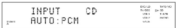
- However, the present input signal will not appear when the input mode is switched during the speaker test mode. Only AUTO will be displayed.
Notes on playing a source encoded with DTS
- Select the DTS mode when playing an LD or CD source encoded with DTS. (Red "dts" indicator is illuminated on the display panel.) If the "AUTO" mode is selected, a noise may be heard just after playback begins.
Do not play these sources in the ANALOG mode because only background noise will be output from the speakers. - This unit is automatically locked in the DTS decoding mode when playing a CD or LD source encoded with DTS in the AUTO mode to prevent background noise in future operation. The red "dts" indicator will be flashing. In the above mode, no sound will be heard if a disc with normal digital signals (PCM) is played from a CD or LD source. The INPUT MODE button on the front panel, or, the input selector key for the current source on the remote controller must be pressed so that "PCM" appears on the display panel.
Recording a source to tape (or MD) or dubbing from tape (or MD) to tape (or MD)
Recording the playing source to tape (or MD)
Note: The cover must be open when using the remote controller.
1 Set the REC OUT selector to the SOURCE position.
Front panel
2 Select the source you want to record. Front panel

Remote control
or
3 Play the source and then turn the VOLUME control up to confirm the input source.
Front panel
Remote control
4 Begin recording to the tape deck (or MD recorder etc.) or VCR connected to this unit.
■ Recording a source to tape (or MD) while listening to (or watching) another source
The source (except for "SOURCE") that is selected with the REC OUT selector can be recorded to a tape deck (MD recorder) and/or VCR, regardless of the INPUT SELECTOR setting.
Note: The cover must be open when using the remote controller.
1 Select the source you want to record.
2 Play the source.
3 Select the source with the INPUT SELECTOR and adjust the VOLUME control to check the sound output.

Front panel
Remote control
or
↓
or
4 Begin recording on the tape deck (or MD recorder etc.) or VCR.
5 The sound and/or picture of the recording can be monitored by selecting the tape deck (or VCR) with the INPUT SELECTOR.

Front panel
Remote control
6 Selecting another source to enjoy with the INPUT SELECTOR will not effect the recording.
Notes on recording
- The VOLUME, BASS, TREBLE, BALANCE controls, the BASS EXTENSION button and the settings of DSP have no effect on the material being recorded.
- Composite video and S video signals pass independently through this unit's video circuits. Therefore, when recording or dubbing video signals, if your video source unit is connected to provide only a S video (or only a composite video) signal, you can record only a S video (or only a composite video) signal on your VCR.
-
A source that is connected to this unit between optical digital terminals only cannot be recorded by a tape deck or VCR other than the tape deck (or MD recorder etc.) connected to the OPTICAL TAPE/MD OUT terminal of this unit.
-
Dolby Digital RF audio input signal cannot be recorded by a tape deck or VCR. To record an LD source, the LD player must be connected to the OPTICAL digital audio signal input terminal and/or analog audio signal input terminals of this unit.
- A source of signals input to the EXTERNAL DECODER INPUT terminals of this unit cannot be recorded.
- Please check the copyright laws in your country to record from records, compact discs, radio, etc. Recording of copyright material may infringe on copyright laws.
If you play back a video source that uses scramble or encoded signals to prevent it from being dubbed, there may be a case that display information superimposed on the picture and/or the picture itself is disturbed due to those signals.
Sound control
Adjusting the BALANCE control
Adjust the balance of the output volume to the left and right speakers to compensate for sound imbalance caused by speaker location or listening room conditions.
Note
This control is effective only for the sound from the main speakers.
Using the BASS EXTENSION button
Press this button inward (ON) to boost the bass frequency response at the main left and right channels while maintaining overall tonal balance. This function is effective for reinforcing the bass frequencies when a subwoofer is not used.
Adjusting the BASS and TREBLE controls
BASS: Turn this knob clockwise to increase (or counter-clockwise to decrease) the low frequency response.
TREBLE:Turn this knob clockwise to increase (or counter clockwise to decrease) the high frequency response.
Note
These controls are effective only for the sound from the main speakers.
Using the TONE BYPASS button
Press this button inward (ON) to bypass the tone (BASS and TREBLE) control circuitry. This function is used for outputting pure sound and checking the tone control settings. The tone control circuitry can be used when this button is released outward (OFF).
Using digital sound field processor (DSP)
This unit incorporates a sophisticated, multi-program digital sound field processor. The processor allows you to electronically expand and change the shape of the audio sound field from both audio and video sources, creating a theater-like experience in your listening room. You can create an excellent audio sound field by selecting a suitable sound field program (this will, of course, depend on what you will be listening to), and adding desired adjustments.
In addition, this unit incorporates a Dolby Digital decoder and a Dolby Pro Logic Surround decoder for multi-channel sound reproduction of sources encoded with Dolby Surround, and a DTS decoder for multi-channel sound reproduction of sources encoded with DTS. The operation of these decoders can be controlled by selecting a corresponding DSP program including a combined operation of YAMAHA DSP and Dolby Digital, Dolby Pro Logic Surround or DTS.
This unit has 12 programs for digital sound field processing; 7 from actual acoustic environments from around the world, and 5 programs for Audio/Video sources. In addition, each program has two subprograms. All programs contain various parameters that can be adjusted to the listener's taste.
For details about digital sound field programs, refer to pages 45 to 49.
Playing a source with an effect of the digital sound field processor (DSP)
1 Follow steps 1 to 7 shown in "Playing a source" on pages 32 to 33.
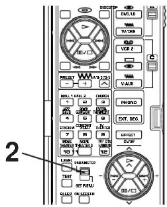
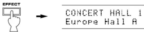
2 When operating on the front panel:
If no program name is illuminated on the display panel, press the EFFECT button to turn on the digital sound field processor so that a name of a DSP program lights up on the display panel and the monitor screen.
When operating on the remote controller:
Set the PARAMETER/SET MENU switch to the PARAMETER position.
Note: The cover of the remote controller must be open.
CONTINUED
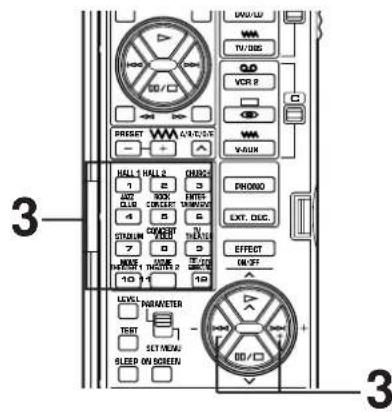
3 Select a program that is suitable for the source.
When operating on the front panel: When operating on the remote controller:
Press once or more.
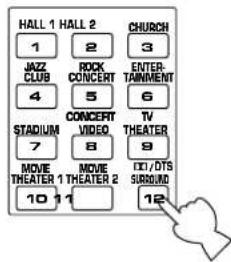
a)
b) Select a desired subprogram by pressing the same DSP program selector key once or more, or by pressing the + / - keys.

The name of the selected program lights up on the display panel and the monitor screen.
4
- Adjust the output level of each speaker. (For details, refer to the corresponding descriptions on pages 43 and 44.)
- You can create your own sound field taste. (For details, refer to pages 54 to 58.)
Notes
- Program selection can be made to individual input sources. Once you select a program, it is linked with the input source selected at this time. So, when you select the same input source the next time, the same program will be automatically recalled.
If you prefer to cancel the DSP, press the EFFECT button. The sound will be the normal 2-channel stereo without surround sound effect. - When a monaural sound source is played with the program PRO LOGIC (Normal/Enhanced), a proper effect will not be obtained. Moreover, sound may become unnatural depending on the settings of the speaker output modes (1A to 1D) in the SET MENU mode.
- When this unit's Dolby Pro Logic Surround decoder, Dolby Digital decoder or DTS decoder is used, if the main-source sound is considerably altered by overadjustment of the BASS or TREBLE control, the relationship between the center and rear channels may produce an unnatural effect.
- When a source of signals input to the EXTERNAL DECODER INPUT terminals of this unit is selected, the DSP cannot be used and the EFFECT button also will not function.
To enjoy a video source encoded with Dolby Pro Logic Surround, Dolby Digital or DTS
When you select the program No. 10, 11 or 12, and the input signal of the source is 2-channel stereo, Dolby Pro Logic Surround is decoded. When some program is selected and the input signal of the source is encoded with Dolby Digital, Dolby Digital is automatically decoded.
When some program is selected and the input signal of the source is encoded with DTS, DTS is automatically decoded.
The following indicators on the display panel show you what sound processing is being made.
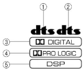
① Lights up when a DVD source encoded with DTS is played back and DTS is decoded.
② Lights up when an LD source or a CD source encoded with DTS is played back and DTS is decoded.
③ Lights up when Dolby Digital is being decoded and the signals of selected source encoded with Dolby Digital is not in 2-channels.
④ Lights up when Dolby Pro Logic Surround is being decoded.
⑤ Lights up when Digital Sound Field Processor is turned on.
The display panel or the monitor screen will show the selected subprogram according to the type of the decoding.
Notes
- Dolby Digital will not be decoded if the source that is not encoded with Dolby Digital.
DTS will not be decoded if the source that is not encoded with DTS. - If the input signals of source encoded with Dolby Digital are in 2-channels only, the sound processing for them is similar to that for analog or PCM audio signals.
The indicator ③ will also light up when the input mode is set to "D.D.RF" even if no signal encoded with Dolby Digital is input to this unit.
Note
If you change the LD (or CD) being played back with DTS decoded to another disc not encoded with DTS when the red "dts" indicator is illuminated, playing back the newly selected disc will output no sound. In this state, the red "dts" indicator flashes to show that this unit is locked in the DTS-decoding mode.
To play back the disc normally, change the current DTS-decoding mode to another mode by pressing an input selector key on the remote controller or the INPUT MODE button on the front panel so that the red "dts" indicator turns off.
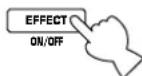
To cancel the effect sound
The EFFECT button on the front panel or the EFFECT ON/OFF key on the remote controller make it simple to compare the normal stereo sound with the fully processed effect sound.
To cancel the effect sound and monitor only the main sound, press the EFFECT ON/OFF key or the EFFECT button. Press the EFFECT ON/OFF key or the EFFECT button a second time to restore the effect sound.

Front panel
Remote control
or
Notes
- If the effect sound is canceled when signals encoded with Dolby Digital or DTS are input to this unit, signals of all channels are mixed and are output from the main speakers.
- If the EFFECT button or the EFFECT ON/OFF key is pressed to turn effect sounds off when Dolby Digital or DTS is decoded, it may happen that sound is output faintly or not output normally depending on a source. In that case, press the EFFECT button or the EFFECT ON/OFF key to turn effect sounds ON, or use input signals not encoded with Dolby Digital or DTS.
- If the EFFECT button or the EFFECT ON/OFF key is pressed to turn effect sounds off, some information is shown on the display panel depending on the type of the current digital input signals. When Dolby Digital is decoded, for example, the sampling frequency and channel formation of the decoded signal is shown on the display panel.
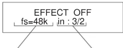
ex.)
Sampling frequency is 48kHz
Three channels at the front Two channels at the rear
- If the input source is a Dolby Digital KARAOKE source, "K" is shown at the head of channel formation.
Adjusting output level of the center, right rear, left rear, front effect speakers and subwoofer
You can adjust the sound output level of the each speaker even if the output level is already set in "Speaker balance adjustment" on pages 29 to 31.
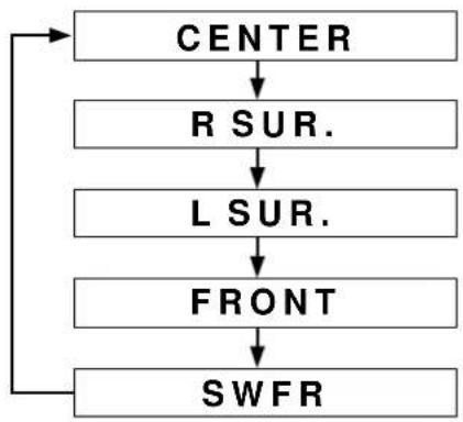
(Center speaker output level)
(Right rear speaker output level)
(Left rear speaker output level)
(Front effect speaker output level)
(Subwoofer output level)
Method of adjustment
This adjustment can be made only by using the remote controller.
Note: The cover of the remote controller must be open.
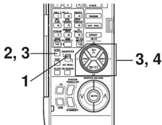
1
Set the PARAMETER/SET MENU switch on the remote controller to the PARAMETER position.

SET MENU
2

3
Press one of the keys shown below once or more until the name of the speaker(s) whose level you want to adjust appears on the display.
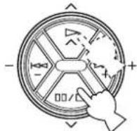
or

Whenever pressed, the selection changes as the above chart shows.
- Pressing the key on the remote controller changes the selection in the reverse order.
4
Adjust the level on the selected speaker(s).
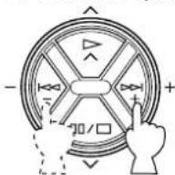
5
Repeat steps 2 and 3 to make adjustments on the other speaker(s).
| Speakers | Control range (dB) | Preset value |
| CENTER | MIN, -20 to +10 | 0 |
| RIGHT SURROUND (R SUR.) | MIN, -20 to +10 | 0 |
| LEFT SURROUND (L SUR.) | MIN, -20 to +10 | 0 |
| FRONT | MIN, -20 to +10 | 0 |
| SUBWOOFER (SWFR) | MIN, -20 to 0 | 0 |
Notes
- Once the output level is adjusted, the level value will be the same in all the digital sound field programs.
- The value of each speaker output level you set the last time will remain memorized even when this unit is in the standby mode.
However, if the power cord is disconnected for more than one week, these values will be automatically changed to the factory default settings.
- If the function "1A. CENTER SP" in the SET MENU mode is set in the "NONE" position, the center speaker output level cannot be adjusted. This is because, in this mode, the center sound is automatically output from the left and right main speakers.
- When one of the DSP programs No. 1 to 7 is selected, the center speaker output level cannot be adjusted.
- When (is not luminated on the display, the front effect speaker output level cannot be adjusted.
Brief overview of digital sound field programs
The following list gives you a brief description of the sound fields produced by each of the DSP programs. Keep in mind that most of these are precise digital recreations of actual acoustic environments. The data for these sound fields were recorded at actual locations using sophisticated sound field measurement equipment.
Note
The channel level balance between the left and right rear effect speakers may vary depending on the sound field you are listening in. This is due to the fact that most of these sound field recreations are actual acoustic environments.
Program No. 1 to 7: Hi-Fi DSP programs (for audio sources)
- When the input signal is analog or PCM audio: (DSP)
Speaker output: main, rear, front effect
- When the input signal is encoded with the Dolby Digital (not in 2 channels): ( DIGITAL DSP)
Speaker output: main, center, rear, front effect
- When the input signal is encoded with the DTS: (DTS DSP)
Speaker output: main, center, rear, front effect
| No. | PROGRAM SUBPROGM (TYPE) | FEATURE | |
| 1 | CONCERT Europe Hall A HALL 1 | This is a large fan-shaped concert hall in Munich which has approximately 2500 seats. Almost the whole interior is made of wood. There is relatively little reflection from the right and left walls, and sounds spread finely and beautifully. | |
| Europe Hall B | A classic shoe-box type concert hall with approximately 1700 seats. Pillars and ornate carvings create extremely complex reflections. Those reflections and the reflections from all directions of the hall produce a very full, rich sound. | ||
| 2 | CONCERT U.S.A. Hall C HALL 2 | This is a large 2600-seat concert hall in the United States which features a fairly traditional European design. The interior is relatively simple, suggesting an American taste. Sound of the middle and high frequencies are richly and beautifully reproduced. | |
| Live Concert | A large round concert hall with a rich surround effect. Pronounced reflections from all directions emphasize the extension of sounds. You will experience the sound field with a great deal of presence sitting at about the center position near the stage. This sound field is also effective for karaoke. This is because you feel as if you are standing on a real stage. | ||
| 3 | CHURCH FREIBUR | Recreates the acoustic environment of a big church with a high pointed dome and columns along the sides. This interior produces very long reverberations. | |
| Royaumont | This program features a sound field created by the refectory (dining hall) of the monastery, a beautiful medieval Gothic structure located in Royaumont on the outskirts of Paris. The dome-like spaces in the ceiling formed by the supporting pillars cause reverberations to echo and create a beautiful, lingering tone. | ||
| No. | PROGRAM SUBPROGRAM (TYPE) | FEATURE | |
| 4 | JAZZ CLUB The Bottom Line | This is the sound field at stage front in “The Bottom Line”, a famous New York Jazz club. The floor can seat 300 people to the left and right in a sound field offering real and vibrant sound. | |
| Village Gate | A jazz club in New York. It is in a basement and has a relatively spacious floor area. The reflection pattern is similar to that of a small hall. | ||
| 5 | ROCK CONCERT | Roxy | Theatreal program for lively, dynamic rock music. The data for this program was recorded at LA's “hottest” rock club. |
| Arena | This program gives you long delays between direct sounds and effect sounds, and extraordinarily spacious feel of a large arena theater. | ||
| 6 | ENTERTAINMENT | Disco | Recreates the acoustic environment of a lively disco in the heart of a very lively city. The sound is dense and highly concentrated. It is also characterized by a high-energy, “immediate” sound. |
| Party | This is a sound field suitable for background music at parties where you can hear the sound directly from the rear as well, thus realizing music enjoyment over a wide area. | ||
| 7 | STADIUM Anaheim | This program gives you the long delays and extraordinarily spacious feel of an outdoor stadium in Los Angeles that is no less than 300 meters (990 feet) in diameter. | |
| Bowl | An outdoor stadium with the typical bowl-shaped seating arrangement. The reflections from seats far from your position are sensed in all directions. | ||
■ Program No. 8 to 12: CINEMA-DSP programs (for Audio/Video sources)
These programs use the Dolby Pro Logic decoder, the Dolby Digital decoder or the DTS decoder.
- Speaker output for each program is as follows.
No.8,9,10,11:main,center,rear,front effect
No. 12 (Normal): main, center, rear
No. 12 (Enhanced): main, center, rear, front effect
- For program No. 8 and 9 only, indicators light up as follows.
When the input signal is analog or PCM audio: (DSP)
When the input signal is encoded with the Dolby Digital (not in 2 channels):

When the input signal is encoded with the DTS: (DSP
| No. | PROGRAM SUBPR OGRAM (TYPE) | FEATURE | |
| 8 | CONCERT Classical Video | Opera | Provides excellent depth of vocals and overall clarity, restraining excessive reverberation. For opera, the orchestra pit and the stage are ideally combined, letting you feel a full presence sound. The rear surround side of the sound field is relatively moderated, however, it reproduces beautiful sound by the use of the data of a concert hall. You will not be tired from long watching of an opera. |
| Pop/Rock | Produces an enthusiastic atmosphere and lets you feel that you are in the midst of the action, as if attending an actual jazz or rock concert. The indirect sound constituent spreads on the surround side of the sound field by the use of data of a large round hall for the surround side, so the image space around the screen and the sound space are fully expanded. | ||
| 9 | TV THEATER Mono | Movie | This program is for reproducing monaural video sources (old movies etc.). Monaural sounds are reproduced with much presence by the front presence side of the sound field and optimum reverberation effect. The use of the center speaker makes conversations more audible, obtaining a pleasant mix of conversations and picture. |
| Variety/Sports | Though the front presence side of the sound field is relatively narrow, the rear surround side employs the sound environment of a large concert hall. With this program, you can enjoy watching various TV programs such as the news, variety shows, music programs or sports programs. In a stereo broadcast of a sports game, the commentator is oriented at the center position, and the shouts and the atmosphere in the stadium spread on the surround side, however, spreading of them to the rear side is properly restrained. | ||
Program No. 10 to 11 are suitable for reproducing video discs, video tapes and similar sources which are encoded with Dolby Surround (bearing the "DOLBY SURROUND" or "DOLBY DIGITAL" logo) or encoded with DTS (bearing the "dts" logo).
| No. | PROGRAM SUBPROGRAM (TYPE) | FEATURE |
| 10 | MOVIE 70 mm SpectacleTHEATER 1 ( | Functions when the input signal is analog or PCM audio or encoded with Dolby Digital in 2 channels.DGTL Spectacle(DISP)Functions when the input signal is encoded with Dolby Digital not in 2 channels.DTS Spectacle(PTS DSP)Functions when the input signal is encoded with DTS. |
| 70 mm Sci-Fi(DPDCD)Functions when the input signal is analog or PCM audio or encoded with Dolby Digital in 2 channels.DGTL Sci-Fi(DPDCD)Functions when the input signal is encoded with Dolby Digital not in 2 channels.DTS Sci-Fi(PTS DSP)Functions when the input signal is encoded with DTS. | ||
| 11 | MOVIE 70 mm AdventureTHEATER 2 ( | Functions when the input signal is analog or PCM audio or encoded with Dolby Digital in 2 channels.DGTL Adventure(DPDCD)Functions when the input signal is encoded with Dolby Digital not in 2 channels.DTS Adventure(PTS DSP)Functions when the input signal is encoded with DTS. |
| 70 mm General(DPDCD)Functions when the input signal is analog or PCM audio or encoded with Dolby Digital in 2 channels.DGTL General(DPDCD)Functions when the input signal is encoded with Dolby Digital not in 2 channels.DTS General(PTS DSP)Functions when the input signal is encoded with DTS. |
Program No. 12 is for reproducing video discs, video tapes and similar sources which are encoded with Dolby Surround (bearing the "DOLBY SURROUND" or "DOLBY DIGITAL" logo) or encoded with DTS (bearing the "dts" logo).
| No. | PROGRAM SUBPR | PROGRAM (TYPE) | FEATURE |
| 12 | DTS PRO LOGIC/Normal() | DTS PRO LOGIC Functions when the input signal is analog or PCM audio or encoded with Dolby Digital in 2 channels. | The built-in Dolby Pro Logic Surround decoder, the Dolby Digital decoder or the DTS decoder precisely reproduces sounds and sound effects of a source encoded with Dolby Surround or DTS. The realization of a highly efficient decoding process improves crosstalk and channel separation and makes sound positioning smoother and more precise. |
| SURROUND Functions | |||
| DOLBY DIGITAL/Normal() Functions when the input signal is encoded with Dolby Digital not in 2 channels. | |||
| DTS DIGITAL SUR./Normal(dts) Functions when the input signal is encoded with DTS. | |||
| PRO LOGIC/Enhanced (DTS LOGIC DSP) Functions when the input signal is analog or PCM audio or encoded with Dolby Digital in 2 channels. | Ideally simulates the multi-surround speaker systems of the newest film theater. The digital sound field processing and the Dolby Surround decoding or the DTS decoding are precisely performed without altering the originally designed sound orientation. The surround effects produced by this sound field fold the viewer naturally from the rear to the left and right and toward the screen. | ||
| DOLBY DIGITAL/Enhanced (DTS DIGITAL DSP) Functions when the input signal is encoded with Dolby Digital not in 2 channels. | |||
| DTS DIGITAL SUR./Enhanced (dts DSP) Functions when the input signal is encoded with DTS. |
Note: If the "NONE" position is selected on "1A. CENTER SP" in the SET MENU mode, no sound is output from the center speaker(s).
ADVANCED FEATURES
"SET MENU" mode
The following eight functions maximize the performance of your system and increase the enjoyment of audio listening and video watching.
1. SPEAKER SET
1A. CENTER SP
1B. REAR SP
1C. MAIN SP
1D. LFE/BASS OUT
1E. SYS. SETUP
1F. MAIN LEVEL
2. DLBY DGTL SET
2A. LFE LEVEL
2B. D-RANGE
3. DTS SET
3A. LFE LEVEL
4. CENTER DELAY
5. PARAMETER INI
6. MEMORY GUARD
7. TV/DBS INPUT
8. DIMMER
Changes and adjustments
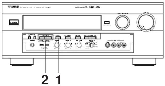
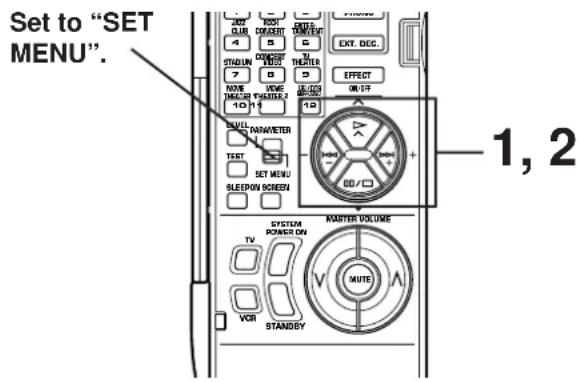
Refer to the information in the display panel or monitor screen during operation. The monitor power must be turned on to display information on the monitor.
When using the remote controller, set the PARAMETER /SET MENU switch to the SET MENU position.
Note: The cover of the remote controller must be open.
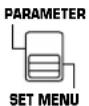
1 To make changes, select the applicable function by pressing one of the following buttons once or more.
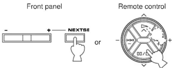
2 Select the desired position or edit parameter for the function by pressing one of the following buttons once or more.
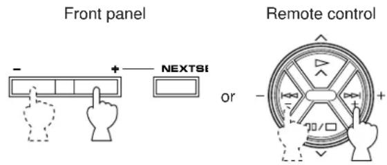
3 Repeat steps 1 and 2 to change a setting or adjust for another function.
Note
A detailed adjusting method is described for each function by using the remote controller keys on pages 51 to 53. When using the front panel buttons, note the following.
- + / - keys on the remote controller are identical with the SET MENU + / - button on the front panel.
- key on the remote controller is identical with the NEXT button on the front panel.
The key on the remote controller can be used to change selections in the reverse order of the key.
Function description
1. SPEAKER SET (Selecting the output modes suitable for your speaker system)
Refer to pages 26 to 27 for details. (Once you have selected proper modes, you do not have to make a setting change, unless your speaker system is modified.)
2. DLBY DGTL (DOLBY DIGITAL) SET
Adjusting method
After selecting the title "2. DLBY DGTL SET" in step 1 on page 50, press the + or - key to display the title "2A. LFE LEVEL". To select the title "2B. D-RANGE", press the key. (To select the title "2A. LFE LEVEL" again, press the key.) Then make a setting change or adjustment with the + or - key.
2A. LFE LEVEL [Adjusting the output level at the LFE (low frequency effect) channel]
Control range: -20 dB to 0 dB Preset value: 0 dB
This adjustment is effective only when Dolby Digital is decoded and the signals of the selected source encoded with Dolby Digital contain LFE signals.
Adjusts the output level at the LFE (low frequency effect) channel. If the LFE signals are mixed with signals of other channels and they are output from the same speakers, the ratio of LFE signals to other signals can be adjusted. (Refer to page 5 for details about the LFE channel.)
2B. D-RANGE (Adjusting dynamic range)
- Choices: MAX/STD/MIN Preset position: MAX
This adjustment is effective only when Dolby Digital is decoded.
"Dynamic range" is the difference between the maximum level and the minimum level of sounds. Sounds on a movie originally designed for movie theaters feature very wide dynamic range.
Dolby Digital technology can bring the original sound track into a home audio format with this wide dynamic range unchanged. Powerful sounds of extremely wide dynamic range are not always suitable for home use. Depending upon the condition of your listening environment, it may not be possible to increase the sound output level as high as a movie theater. However, in a level suitable for listening in your room, the low level parts of source sound cannot be heard well because they will be lost among noises in your environment.
Dolby Digital technology also made it possible to reduce an original sound track's dynamic range for a home audio format by "compressing" the data of sound.
MAX: In this position, a source encoded with Dolby Digital is reproduced in the original sound track's wide dynamic range providing you with powerful sounds like a movie theater.
Selecting this position will be more ideal if you can listen to a source in a high output level in a room specially soundproofed for audio/video enjoyment.
STD (Standard):
In this position, a source encoded with Dolby Digital is reproduced in the "compressed" dynamic range of the source suitable for low level listening.
MIN: In this position, dynamic range is more reduced than in the STD position. Selecting this position will be effective when you must listen to a source in an extremely low level.
- In this position, it may happen that sound is output faintly or not output normally depending on a source. In that case, select the MAX or STD position.
3. DTS SET
Adjusting method
After selecting the title "3. DTS SET" in step 1 on page 50, press the + or - key to display the title "3A. LFE LEVEL". Then adjust its level with the + or - key.
3A. LFE LEVEL [Adjusting the output level at the LFE (low frequency effect) channel]
Control range: -10 dB to 10 dB Preset value: 0 dB
- This adjustment is effective only when DTS is decoded and the signals of the selected source encoded with DTS contain LFE signals.
Adjusts the output level at the LFE (low frequency effect) channel. If the LFE signals are mixed with signals of other channels and they are output from the same speakers, the ratio of LFE signals to other signals can be adjusted. (Refer to page 5 for details about the LFE channel.)
4. CENTER DELAY [Adjusting the delay of center sounds (dialog etc.)]
Control range: 0 ms to 5 ms (in 1 ms step) Preset value: 0 ms
- This adjustment is effective only when Dolby Digital or DTS is decoded and the signals of the selected source encoded with Dolby Digital or DTS contain center channel signals.
Adjusts the delay between the main sounds (at the main channels) and dialog etc. (at the center channel). The larger the value, the later the dialog etc. is generated. In your audio system, the distance from the center speaker to your listening position may be shorter than the distance from the left or right main speaker to your listening position. In that case, sounds from the left main, center and right main speakers can reach your listening position at the same time by delaying the sound from the center speaker.
5. PARAMETER INI (Initializing parameters on a DSP program)
You can initialize all parameter settings on a DSP program. Note that a DSP program has two or three subprograms; all parameters on both subprograms are initialized by this operation.
Initializing method
After selecting this function (title) in step 1 on page 50, press the + or - key to display the DSP program numbers (1-12). A program number whose parameters has been changed is marked with . Press a DSP program selector key corresponding to the program number whose parameters you want to initialize. When initialized, the mark will disappear.
6. MEMORY GUARD (Locking DSP parameters and other adjustments)
If you wish to prevent accidental alteration to DSP parameters and other adjustments on this unit, select "ON". In this position, they are locked and cannot be changed. The following functions on this unit can be locked by this operation.
DSP parameters
- Other functions in the "SET MENU" mode
- ON SCREEN display key
LEVELkey
TEST key
7. TV/DBS INPUT (Selecting the initial input mode of the source connected to the TV/DBS input terminals)
For the source connected to the TV/DBS input terminals of this unit, you can designate the input mode that is automatically selected when the power of this unit is switched on.
AUTO: In this position, the AUTO input mode is always selected when the power of this unit is switched on.
LAST: In this position, the input mode you have selected the last time is memorized and will not be changed even if the power of this unit is switched off.
- Refer to page 35 for details about switching the input mode.
8. DIMMER (Changing brightness of the display panel)
You can adjust the brightness of the display panel in five degree increments.
Creating your own sound fields
What is a sound field?
In order to explain the impressive functions of the DSP, we need to first understand what a sound field really is.
What really creates the rich, full tones of a live instrument are the multiple reflections from the walls of the room. In addition to making the sound "live", these reflections enable us to tell where the player is situated, and the size and shape of the room in which we are sitting. We can even tell whether it is highly reflective with steel and glass surfaces, or more absorbent with wood panels, carpeting and curtains.
The elements of a sound field
In any environment, in addition to the direct sound coming straight to our ears from the player's instrument, there are two distinct types of sound reflections that combine to make up the sound field:
(1) Early Reflections.
Reflected sounds reach our ears extremely rapidly (50 ms - 100 ms after the direct sound), after reflecting from one surface only—for example, from the ceiling or a wall. These reflections fall into specific patterns as shown in the diagram on page 56 for any particular environment, and provide vital information to our ears. Early reflections actually add clarity to the direct sound.
(2) Reverberations.
These are caused by reflections from more than one surface—walls, ceiling, the back of the room—so numerous that they merge together to form a continuous sonic "afterglow". They are non-directional, and lessen the clarity of the direct sound.
Direct sound, early reflections and subsequent reverberation taken together help us to determine the subjective size and shape of the room, and it is this information that the DSP reproduces in order to create sound fields.
If you could create the appropriate early reflections and subsequent reverberations in your listening room, you would be able to create your own listening environment. The acoustics in your room could be changed to those of a concert hall, a dance floor, or virtually any size room at all. This ability to create sound fields at will is exactly what Yamaha has done with the DSP.
DSP programs consist of some parameters to determine apparent room size, reverberation time, distance from you to the performer, etc. In each program, these parameters are preset with values precisely calculated by Yamaha to create the sound field unique for the program. It is recommended to use DSP programs without changing values of parameters, however, this unit also allows you to create your own sound fields. Starting with one of the built-in programs, you can adjust those parameters. Even if the power cord of this unit is disconnected from the AC outlet, your custom sound fields will remain in the DSP's memory for about two weeks. The following page details how to make your own sound fields.
In addition to the "TYPE" parameter which selects the subprograms within each DSP program (for example, "Europe Hall A", and "Europe Hall B" for the program 1, "CONCERT HALL 1"), each program also has a set of parameters that allow you to change the characteristics of the acoustic environment to precisely create the effect you want. These parameters correspond to the many natural acoustic factors that create the sound field you experience in an actual concert hall or other listening environment. The size of the room, for example, affects the length of time between the "early reflections"-that is, the first few widely spaced reflections you hear after the direct sound. The "ROOM SIZE" parameter provided in many of the DSP programs alters the timing between these reflections, thus changing the shape of the "room" you hear. In addition to room size, the shape of the room and the characteristics of its surfaces have a significant effect on the final sound. Surfaces that absorb sound, for example, cause the reflections and reverberations to die out quicker, while highly reflective surfaces allow the reflections to carry on for a longer period of time. The DSP parameters allow you to control these and many other factors that contribute to your personal sound field, allowing you to essentially "redesign" the concert halls, theaters, etc. provided to create custom-tailored listening environments that ideally match your mood and music.
Refer to "Descriptions of the digital sound field parameters" on pages 56 to 58 for a description of what each parameter does, how it effects the sound, and its control range.
Selecting and editing program parameters
This adjustment can be made only by using the remote controller and watching the monitor screen or the display panel.
Note
Information on the monitor screen would be easier to see than the display panel.
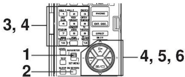
1 Set the PARAMETER/SET MENU switch to the PARAMETER position.
Note: The cover of the remote controller must be open.
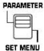
2 Turn your monitor on. If the currently selected type of display is not the full display, press the ON SCREEN display key and select the full display.

3 If no DSP program is selected, select a desired program.
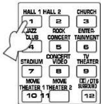
The selected program name and its parameters will be displayed on the monitor screen. The arrow-shaped cursor points to the subprogram name.
P01 CONCERT HALL 1
→ Europe Hall A
INIT. DELAY·29ms
ROOM SIZE……1.0
LIVENESS……5
Subprogram
4 Select the desired subprogram.
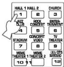
or
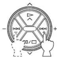
Press the button for the currently selected program once or more.
5 Select the parameter which you want to edit.
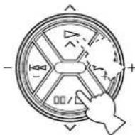
6 Change the value on the selected parameter to create the effect you want.

^ + increases the value of the selected parameter, and - decreases the value of the selected parameter. In both cases you can hold the key down to quickly move to the desired value.
The display will pause for a moment at the initial set value of the parameter as a reminder. (On the monitor screen, the mark at the head of the parameter name will disappear upon reaching the initial set value of the parameter.)
Notes
For details about parameters, refer to pages 56 to 58.
- Parameter edits made in this way will remain in effect even if power is lost due to a power failure or the power plug is disconnected from the AC outlet for about two weeks, after which all parameters, as well as other adjustments or setting changes on this unit, will return to their initial values or conditions.
Descriptions of the digital sound field parameters
Not all of the following parameters are found in every program.
- ROOM SIZE
How it Affects the Sound:
Changes the apparent size of the music venue. The larger the value, the larger the simulated room will sound.
What it Does:
Adjusts the timing between the early reflections. Early reflections are the first group of reflections you hear before the subsequent, dense reverberation begins.
Control Range:
0.1-2.0
Standard setting is 1.0.
Changing this parameter from 1 to 2 increases the apparent volume of the room eight times (length, width, and height all doubled).
P. ROOM SIZE (Presence Room Size)
Adjusts the apparent space size of the front presence sound field. The larger the value, the longer the interval between reflections becomes, which increases the depth of the sound source.
S. ROOM SIZE (Surround Room Size)
Adjusts the apparent space size of the rear surround sound field. The larger the value, the larger the surround sound field becomes.
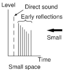
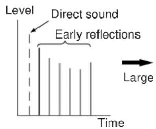
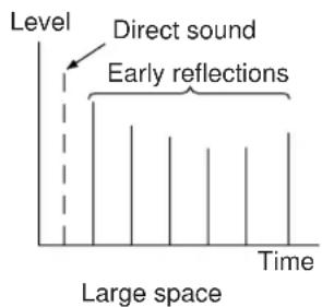
- INIT. DLY (Initial Delay)
How it Affects the Sound:
Changes the apparent distance from the source sound.
Since the distance between a sound source and a reflective surface determines the delay between the direct sound and the first reflection, this parameter changes the location of the sound source within the acoustic environment.
What it Does:
Adjusts the delay between the direct sound and the first reflection heard by the listener.
Control Range:
1-99 milliseconds
For a small living room this parameter would be set for a small value. Large values for a big room. Larger values produce an echo effect.
P. INIT. DLY (Presence Initial Delay)
Adjusts the delay between the direct sound and the first reflection on the presence side of the sound field. The larger the value, the later the first reflection begins.
Control Range:
1-99 milliseconds
S. INIT. DLY (Surround Initial Delay)
Adjusts the delay between the direct sound and the first reflection on the rear surround side of the sound field. The larger the value, the later the first reflection begins.
Control Range:
1-49 milliseconds
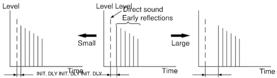
LIVENESS
How it Affects the Sound:
This parameter changes the apparent reflectivity of the walls in the hall.
The early reflections from a sound source will lose intensity (decay) much faster in a room with acoustically absorbent wall surfaces than in one which has mostly reflective surfaces. A room with highly reflective surfaces in which the early reflections decay slowly is termed "live", while a room with absorbent characteristics in which the reflections decay rapidly is termed "dead". The LIVENESS parameter lets you adjust the early reflection decay rate, and thus the "liveness" of the room.
LIVENESS (Presence Liveness)
Adjusts the apparent reflectivity of the walls on the front presence sound field. The larger the value, the more reflective the front presence sound field becomes.
S. LIVENESS (Surround Liveness)
Adjusts the apparent reflectivity of the walls on the rear surround sound field. The larger the value, the more reflective the rear surround sound field becomes.
What it Does:
Changes the rate at which the early reflections decay.
Control Range:
0-10.
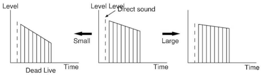
REV. TIME (Reverberation Time)
How it Affects the Sound:
The natural reverberation time of a room depends primarily on its size and the characteristics of its inner surfaces. This parameter, therefore, changes the apparent size of the acoustic environment over an extremely wide range.
What it Does:
Adjusts the amount of time it takes for the level of the dense, subsequent reverberation sound to decay by 60 dB (1 kHz).
Control Range:
1.0 - 5.0 seconds.
The reverb time in a small-to-medium size hall would be between 1 and 2, and in a large hall it is normally between 2 and 3.
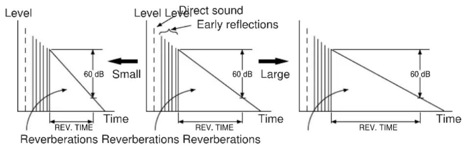
REV. LEVEL (Reverberation Level)
This parameter adjusts the volume of the reverberation sound. The larger the value, the stronger the reverberation becomes.
Control Range:
0-100%
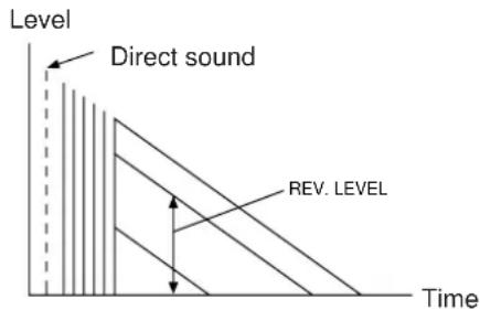
S. DELAY (Surround Delay)
Adjusts the delay between the direct sound and the first reflection on the rear surround side sound field. The larger the value, the later the surround sound field is generated.
Control Range:
When Dolby Pro Logic Surround is decoded:
15-30 milliseconds
When Dolby Digital or DTS is decoded:
0-15 milliseconds
When a program without Dolby Surround or DTS
encoded is used:
15-49 milliseconds
Setting the SLEEP timer
Use the built-in SLEEP timer to automatically turn this unit into the standby mode after the time you set elapses. The SLEEP timer is useful when you plan to fall asleep while this unit is playing back or recording a source. The SLEEP timer also automatically turns off external units connected to the SWITCHED AC OUTLET(S) on the rear of this unit. The SLEEP timer can only be set using the remote controller.
To set the SLEEP time
1 Select the source using the INPUT SELECTOR and start playback (or select a broadcast station) on the source unit.
2 Press the SLEEP key repeatedly until the desired SLEEP time appears on the display.
- "SLEEP time" is the time that elapses before this unit is automatically turned into the standby mode.
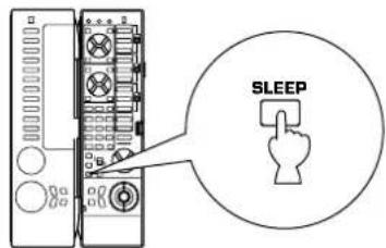
Indicates the SLEEP time.
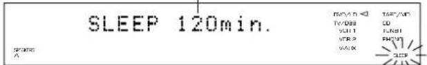
Flashes.
Each time you press the SLEEP key, the SLEEP time changes as follows.
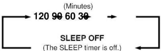
After a while, the display returns to the original indication.
To cancel the SLEEP timer
Press the SLEEP key repeatedly until "SLEEP OFF" appears on the display. (After a while, the display returns to the original indication.)
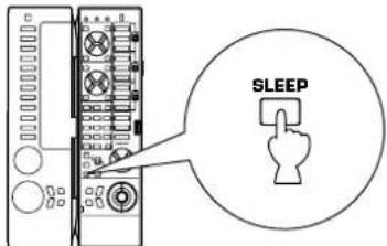
Note
The SLEEP timer setting can also be canceled by setting this unit into the standby mode with the STANDBY/ON switch on the front panel (or the STANDBY key on the remote controller) or disconnecting the power plug of this unit from the AC outlet.
REMOTE CONTROLLER
The remote controller can operate the main unit as well as other Yamaha audio and video components. The Macro feature allows you to program a series of functions in sequence onto a single key, or you can use one of the preset macros to operate other Yamaha components in your home theater. This remote controller also has a sophisticated Learn feature that allows it to acquire functions from other remote controllers you use with other components in your system (or other household appliances) equipped with infrared remote control receivers. This feature makes it possible for you to reduce the number of remote controllers in your listening room.
Basic operation (Cover is open)
The remote controller is designed to control the most commonly used functions. If the CD player, tape deck, LD player, etc. is a YAMAHA component with remote control compatibility, this remote controller will also control various functions.
- For basic operations, the cover must be opened.
Key name and function
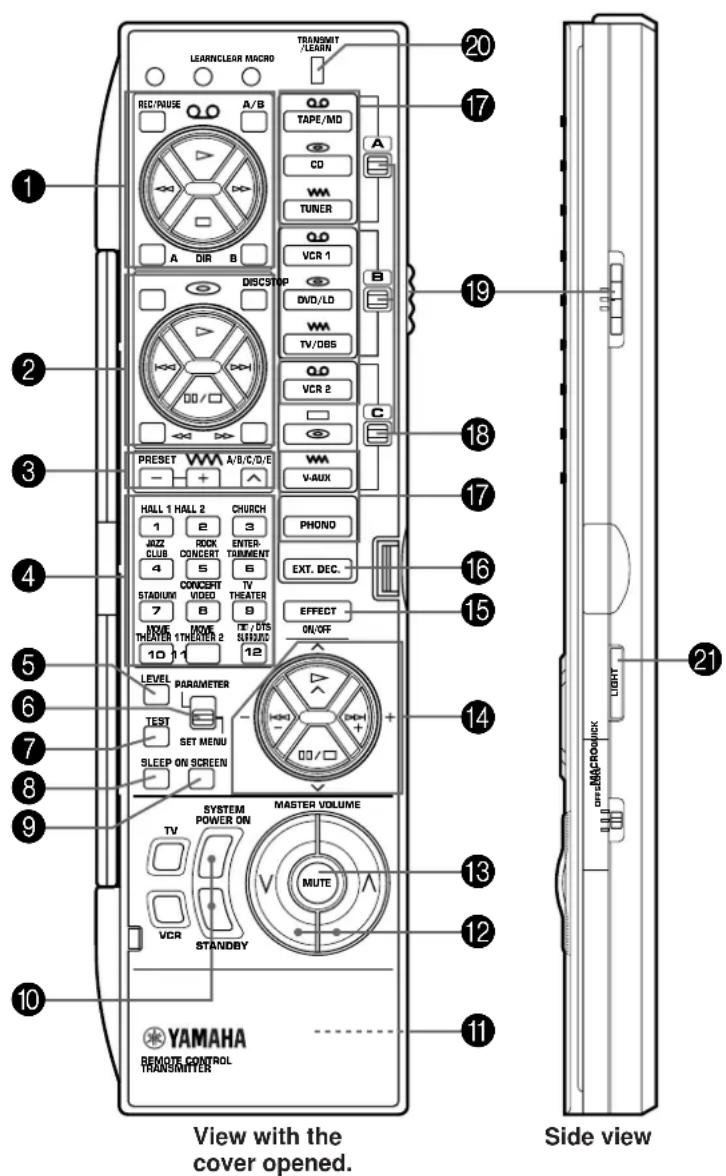
TAPE/MD keys
These keys control tape decks or MD recorders.
The A/B/C switch (19) should be set to the "A" position to control tape decks, and "C" position for MD recorders.
- The DIR A, B and A/B keys apply only to double cassette tape decks.
- Pressing the DIR A key will reverse the tape direction on a single cassette tape deck with the automatic reverse function.
- The and keys work as follows.
For tape decks:
: Rewinds a tape.
: Advances a tape fast.
For MD recorders:
: Locates the beginning of the current or previous track.
: Locates the beginning of the next track.
CD/DVD/LD player keys
These keys control compact disc players, DVD players or LD players.
Set the A/B/C switch (19) to the "A" position to control compact disc players, "B" position for DVD players and "C" position for LD players.
The DISC key is used for disc changers only.
The STOP key is used for DVD players and LD players only.
3 Tuner keys
Control tuners.
The A/B/C switch (19) should be set to the "A" position.
+: Press this key to select the next preset station number.
-: Press this key to select the previous preset station number.
A/B/C/D/E: Selects the group (A-E) of preset station numbers.
DSP program selector keys
Press a key to select a DSP program when the built-in digital sound field processor is on. Includes the Dolby Pro Logic Surround decoder, Dolby Digital decoder, and DTS decoder.
LEVEL key
This key is used to adjust the output level of the center, rear and front effect speakers, and subwoofer. First, press this key (several times) to select the speaker(s). The name will be illuminated on the display. Then press the + or - keys (14) to change the output level.
PARAMETER/SET MENU switch
Set this switch to "PARAMETER" to edit a DSP program parameter. Set to "SET MENU" to adjust or make changes in a function in the SET MENU mode.
TESTkey
This key is used when adjusting the speaker balance. (Refer to pages 29 to 31.)
SLEEP timer key
Press this key to turn the built-in SLEEP timer on and off, and set the SLEEP time. (Refer to page 59.)
9 ON SCREEN display key
Press this key to change the type of display on the monitor screen. Three types of displays are available.
Each time the key is pressed, the information can be changed to a full, simple and no display.
10 SYSTEM POWER ON and STANDBY keys
Press the SYSTEM POWER ON key to turn on the power.
Press the STANDBY key to set this unit in the standby mode.
11 RESET button
This button is inside the battery compartment.
Press this button to reset the internal microcomputer for controlling remote control operations. This button is used when the remote controller " freezes".
- Learned functions will not be erased when this button is
pressed.
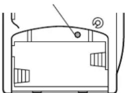
RESET button
12 MASTER VOLUME (up) and (down) keys
Press these keys to increase or decrease the volume.
13 MUTE key
Press this key to mute the volume. The volume can be returned to the original level by pressing any remote controller key which controls this unit. The indicator on the VOLUME control flashes during the mute mode.
14 / and-/+keys
The (up) and (down) keys change the parameters or functions according to the mode selected by the PARAMETER/SET MENU switch. The - and + keys adjust or make changes in the parameter or function.
15 EFFECT ON/OFF key
Press this key to turn on/off the digital sound field processor, which includes the Dolby Pro Logic Surround decoder, Dolby Digital decoder and DTS decoder.
16 EXT. DEC. key
Press this key to select the input signals from the EXTERNAL DECODER INPUT terminals as the input source. This function takes priority over the input selector key setting. "EXT. DECODER IN" will be illuminated on the display panel. The source selected with the input selector keys becomes the current input source when "EXT. DECODER IN" is not illuminated on the display panel.
17 Input selector keys
Press a key to select the input source.
18 A/B/C indicators
One of these indicators will turn to red depending on the position of the A/B/C switch.
19 A/B/C switch
Normally this switch is set to the "A" position. Use the "B" position to control a Yamaha DVD player with the CD/DVD/LD player keys (2). Use the "C" position to control a Yamaha LD player with the CD/DVD/LD player keys (2), or control a Yamaha MD recorder with the TAPE/MD keys (1).
TRANSMIT/LEARN indicator
This indicator will be illuminated when a key is pressed on the remote controller. (Transmitting infrared signals.)
21 LIGHT key
Press this key to turn on the light for some of the keys about 5 seconds. The light can be turned off by pressing the key again.
Note
The functions of the keys to control other Yamaha components are the same as the corresponding keys on those components. Refer to those components' instruction manuals for details.
Using the "learning-capable" keys (Cover is open)
This is a learning remote controller. The shaded keys in the illustration shown below can be programmed to "learn" control functions from other remote controllers. This unit can be used in place of other remote controllers by learning their functions. It will be much convenient for you to operate various audio and video components.
Some of the "learning-capable" keys are originally empty and others have already been preset with functions to control this unit and other Yamaha components. You can store new functions to them (in place of preset functions) as desired.
- See page 68 for the learning method.
- See page 70 for clearing a learned function (or all learned functions).
Note
If the memory capacity of the remote controller becomes full, no further learning is possible even if some learning-capable keys are not occupied with new functions. If, for example, you store Yamaha codes only into this remote controller, up to about 50 functions can be stored. Therefore, we recommend that only required functions be stored.
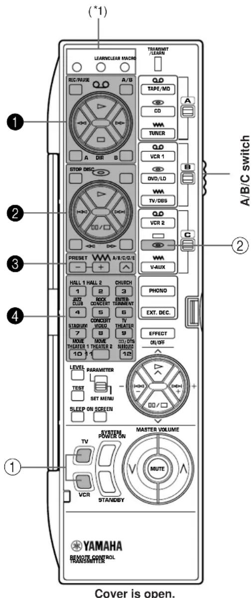
(^*1) : These buttons are used for learning a new function or clearing a learned function (or all learned functions). For details, refer to pages 68 to 70.
Keys which can have three functions (1, 2, 3, 4)
In the "Learning-capable" keys, the keys numbered 1-4 in the illustration on the left can have three functions. This is because they have three memory areas (A, B and C). (One function per area.) You can store new functions into the area B and C, and use three functions on a key by switching the memory areas with the A/B/C switch. (Area A cannot learn a new function.)
To use these keys:
- Before using a key, select area A, B or C of the key on which the function you want to use is stored by using the A/B/C switch.
- Press the key.
The default settings of these keys are as follows.
| The position of A/B/C switch | |||
| TAPE/MDCDWATUNER | QCDVR 1CDVD/LDTV/DBS | QCDVR 2CDWATUNER | |
| 1Qo | Preset with functions for controlling a Yamaha tape deck. | Empty | Preset with functions for controlling a Yamaha MD recorder (except the model MDX-9). (A/B, DIR A and B are empty.) |
| 2Qo | Preset with functions for controlling a Yamaha CD player.(STOP is empty.) | Preset with functions for controlling a Yamaha DVD player(except the models DVD-1000 and DVD-S700). | Preset with functions for controlling a Yamaha LD player.(DISC is empty.) |
| 3WM | Preset with functions for controlling a Yamaha tuner. | Empty | Empty |
| 4 | Preset as the DSP program selector keys. | Preset as the DSP program selector keys. | Preset as the DSP program selector keys. |
Notes
- Area A cannot learn a new function. To store a new function, store it onto area B or C.
- If a key which has a preset function learns a new function, the preset function will not work but is not deleted. When the learned function is cleared, the preset function is restored. (For information on clearing a learned function, refer to page 70.)
Empty keys (1, 2)
These are empty keys. Each key can learn a function from another remote controller.
For example, the TV key is useful for storing the function of your TV's power switch, and the VCR key can be used for your VCR's power switch.
About the marks on the remote controller
| Mark | Meaning |
| 0.0 | Tape (Tape deck, VCR, etc.) |
| © | Disc (CD player, LD player, etc.) |
| WM | Radio wave (Tuner, TV/BS tuner, etc.) |
An input selector key and other control keys which have the same mark will work for the same input source. These marks are also helpful for storing new functions.
Examples)
- Area B of keys ① is suitable for storing functions to control your VCR.
- Area B of keys 3 is suitable for storing functions to control your TV/BS tuner.
About the lighting of keys
When you press an input selector key, it lights up for about 3 seconds.
When an input selector key in the group of selected memory area (A, B or C) is pressed, the mark of a key group (1-3) which is the same as the mark of the selected input selector key lights up for about 3 seconds.
Example:
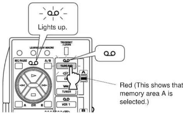
Conversely, when a key of the group 1-3 is pressed, its mark and the input selector key with the same mark in the group of the selected memory area light up for about 3 seconds.
This feature may be helpful for you if you store functions for controlling an input source to a group of keys whose mark lights up when the corresponding input selector key is pressed.
To record new functions
It is recommended that you write down stored key functions on the provided user function stickers and paste them on the reverse side of the remote controller or the reverse side of the remote controller's cover.
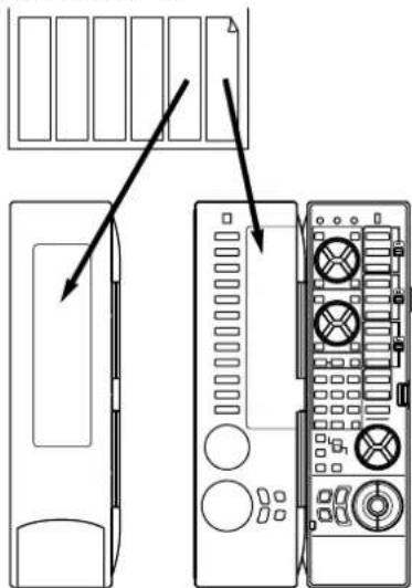
Memory back-up
All of the learned functions will be retained while you replace the batteries. However, if no batteries are installed for a few hours, the learned functions will be erased and will have to be learned again.
Using OPERATION CONTROL keys (Cover is closed)
When the cover of the remote controller is closed, you can easily operate Yamaha components including learned functions by using the OPERATION CONTROL keys.
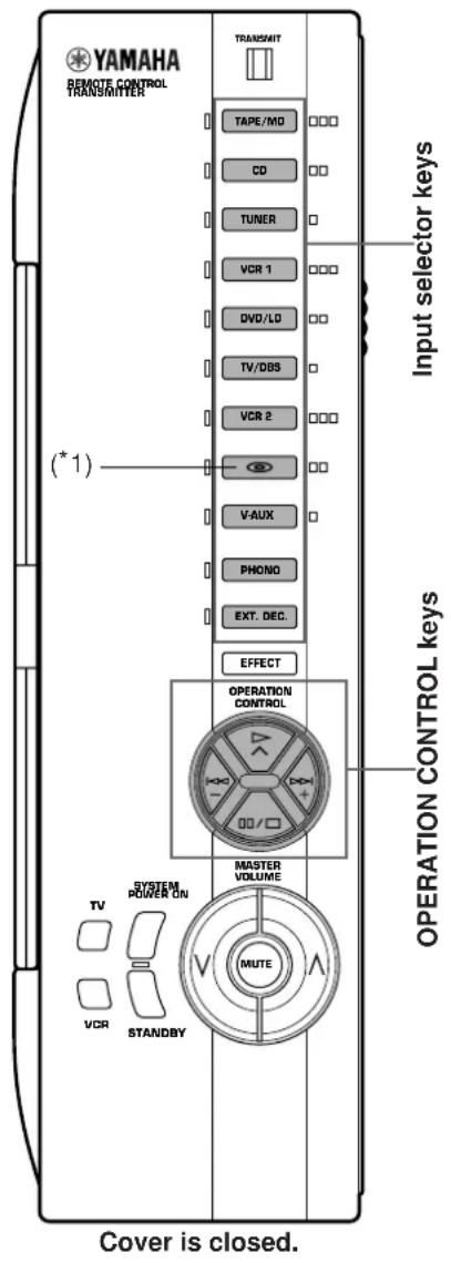
When the cover is closed, the OPERATION CONTROL keys substitute for the keys numbered 1, 2 or 3 on the above illustration. To use these keys, you do not have to switch the A/B/C switch. The functions of the OPERATION CONTROL keys are determined by the input selector key pressed before using the OPERATION CONTROL keys.
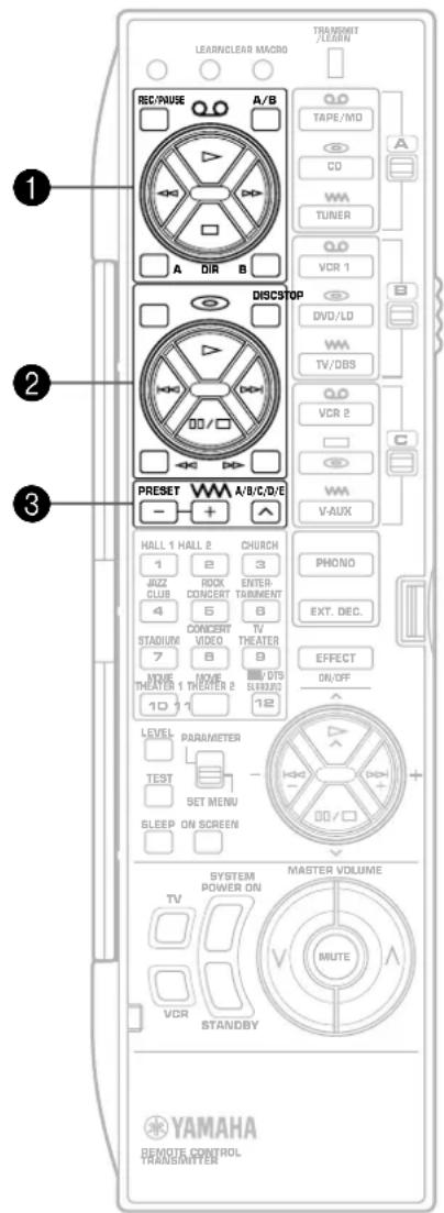
Note
Whether the cover is opened or closed, the EFFECT, MASTER VOLUME, MUTE, TV and VCR keys will not change their functions.
- If the MACRO switch on the side of the remote controller is set to "OFF", the SYSTEM POWER ON and STANDBY keys will not also change their functions whether the cover is opened or closed.
(^*1) : This key is originally empty. If this key has a learned function, pressing this key executes the learned function.
Examples of operations controlled by using the OPERATION CONTROL keys
To operate a Yamaha CD player
- Press the "CD" input selector key.
- Use the OPERATION CONTROL keys. (They carry out the functions in area A of keys ②.)
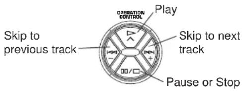
To operate your VCR
- Press the "VCR" input selector key.
- Use the OPERATION CONTROL keys. (They carry out the functions in area B of keys 1. This area is originally preset with no function. You must store the functions related to controlling the VCR in area B of keys 1 beforehand.)
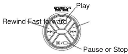
See the table below for a combination of an input selector key and key functions which the OPERATION CONTROL keys carry out. (Also, refer to the table on page 62.)
| Selected input selector key | Key functions which the OPERATION CONTROL keys carry out |
| TAPE/MD | Functions in area A of keys ① (except REC/PAUSE, A/B, DIR A and B) |
| CO | Functions in area A of keys ② (except STOP, DISC, < and >) |
| TUNER | Functions in area A of keys ③ |
| VCR 1 | Functions in area B of keys ① (except REC/PAUSE, A/B, DIR A and B) |
| DVD/LD | Functions in area B of keys ② (except STOP, DISC, < and >) |
| TV/DBS | Functions in area B of keys ③ |
| VCR 2 | Functions in area C of keys ① (except REC/PAUSE, A/B, DIR A and B) |
| SAux | Functions in area C of keys ② (except STOP, DISC, < and >) |
Pressing the "PHONO" or "EXT. DEC." input selector key has no effect on the OPERATION CONTROL keys.
Notes
- If an OPERATION CONTROL key is substituted for a key which has no function (empty), then a command will not be carried out.
Depending on your plan, store functions from other remote controllers into an empty area of those keys. (Refer to page 68 for the learning method.)
- While playing an audio/video unit, if you want to operate another unit by using the remote controller (for example, if you want to rewind a videotape while listening to a CD), you should open the cover of the remote controller and use the A/B/C switch and the corresponding keys.
(If you press an input selector key with the cover closed to change the functions of the OPERATION CONTROL keys to the functions for controlling a VCR, the input of currently playing CD source is canceled.)
About the lighting of keys
When an input selector key is pressed, the pressed key and only the available OPERATION CONTROL keys (which substitute for the keys stored with the preset functions or learned functions) light up for about 3 seconds. So you will know what keys are available at a glance.
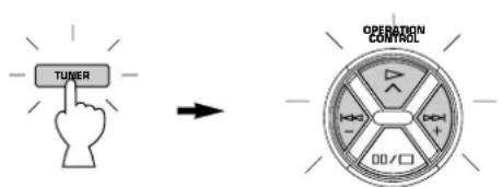
Conversely, when an OPERATION CONTROL key is pressed, all of the available OPERATION CONTROL keys and the currently selected input selector key light up.
Macro operations (Cover is closed)
The Macro feature makes it possible to operate a series of functions by pressing just one key. For example, when you want to play a CD, normally you would turn on the equipment, select the CD input, and press the play key to start playback. Using the Macro feature you can operate all those functions by simply pressing the CD macro key. The preset macro keys (the input selector keys and SYSTEM POWER ON/STANDBY keys with an orange mark next to them) are preset with macro programs. If you prefer, however, you can change the contents of a macro key by storing a desired series of functions on it. You can store up to seven functions onto a macro key. (Refer to page 69 for making a new macro.)
Macros can be used only when the cover is closed and the MACRO switch is set to "SLOW" or "QUICK". (If "OFF" is selected, no macro will function even if the cover is closed.)
Setting the MACRO switch
OFF: In this position, no macro will function even if the cover of the remote controller is closed.
QUICK: In this position, when a macro key is pressed, each command is transmitted at 0.5 second intervals.
SLOW: In this position, when a macro key is pressed, each command is transmitted at 3 second intervals.
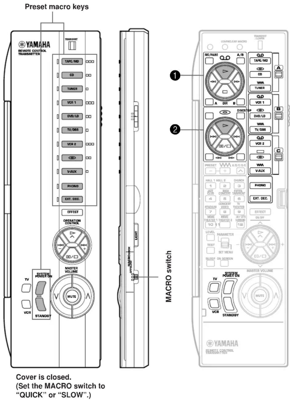
The Macro feature allows you to operate several remote control functions in a programmed order by pressing one macro key. (Also, refer to the table on page 62.)
| Macro key | Function of the key (and area) carried out when a macro key is pressed | ||
| 1st(Turns on this unit.) | 2nd(Selects an input source.) | 3rd(Starts playback of a source.) | |
| I TAPE/MD | SYSTEM POWER ON | TAPE/MD | “▷” on area A of ke1 |
| I CD | CD | “▷” on area A of keys ② | |
| I TUNER | TUNER | - | |
| I VCR 1 | VCR 1 | “▷” on area B of ke1 | |
| I DVD/LD | DVD/LD | “▷” on area B of keys ② | |
| I TV/DBS | TV/DBS | - | |
| I VCR 2 | VCR 2 | “▷” on area C of ke1 | |
| I ⑤ | ⑤ | “▷” on area C of keys ② | |
| I V-AUX | V-AUX | - | |
| I PHONO | PHONO | - | |
| I EXT. DEC. | EXT. DEC. | - | |
| Macro key | Function of the key carried out when a macro key is pressed | ||
| 1st | 2nd | 3rd | |
| SYSTEM POWER ON | Turns on this unit. | Carries out the function of the TV key. | Carries out the function of the VCR key. |
| SYSTEM POWER ON | TV | VCR | |
| STANDBY | Sets this unit to the standby mode. | - | - |
| STANDBY | |||
Notes
- A key in which no function is stored will carry out no command.
- If it occurs that this unit will not receive the second command because the internal operation of the first command takes a long time, set the MACRO switch to the "SLOW" position.
-
Once you press a macro key, this unit will not receive the command of another key (even if it is pressed) until this unit finishes carrying out all commands of the macro key. Take notice of this especially when the MACRO switch is in the "SLOW" position.
-
Once you press a macro key, you must keep the remote controller directed at the main unit's remote control sensor until the remote controller finishes transmitting all command signals of the macro key.
- You can also use the OPERATION CONTROL keys while using the macro functions.
Methods of learning and clearing functions
Learning a new function
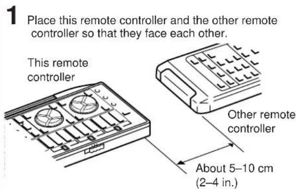
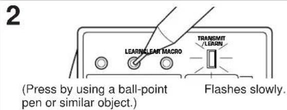
- If there is no operation for about 30 seconds after the LEARN button is pressed, the TRANSMIT/LEARN indicator flashes rapidly and the current mode is canceled. Repeat this step.
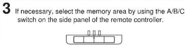
4 Press the key on this remote controller in which you will store a new function.
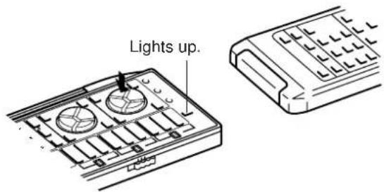
- If a key which cannot learn another function is pressed, the TRANSMIT/LEARN indicator flashes rapidly and the current mode is canceled. Repeat this step.
- If there is no operation for about 30 seconds after a key is pressed, the TRANSMIT/LEARN indicator flashes rapidly and the mode before you began learning operations is restored. Restart from step 2.
5 Press and hold the key (on the other remote controller) which has the function you want to store.
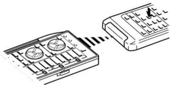
When learning is finished, the TRANSMIT/LEARN indicator stops lighting. You can release the key. Then the indicator begins flashing slowly.
- If a signal is not successfully received, the TRANSMIT/LEARN indicator flashes rapidly and the mode prior to step 4 is restored. Restart from step 4.
- If memory capacity is full, the TRANSMIT/LEARN indicator flashes rapidly to show you that learning is impossible, and then the mode before you began learning operations is restored.
6 Repeat steps 3-5 to store more functions.
7 When you finish the learning operation, press the LEARN button.
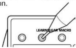
Notes
- Newly learned functions will replace previously learned functions.
If there is no more room in the memory area for a function to be learned, the TRANSMIT/LEARN indicator will flash rapidly. In this case, even if some keys are not occupied with functions from other remote controllers, no further learning is possible.
If you close the cover while learning, and then about 5 seconds pass, the TRANSMIT/LEARN indicator flashes rapidly and the mode before beginning learning operations is restored. Restart from step 2. However, if you open the cover within 5 seconds, the mode before closing the cover is restored. - There may occasionally be instances in which, due to the signal-coding and modulation employed by the other remote controller, this remote controller will not be able to "learn" its signals.
- When you press the LEARN, MACRO or CLEAR button, or the RESET button inside of the battery compartment by using a sharp-pointed thing, be careful not to damage the button. If you will use a mechanical pencil, make sure that the lead is retracted.
Making a new macro
A new macro can be programmed onto any preset macro key in place of the factory preset functions. (See page 66 to know what keys are preset macro keys.) You can make as many as 13 new macro keys. A macro key can learn as many as seven functions of other keys.
Note
If you store a continuous function such as lowering the volume level, it may not work well when carried out as a part of macro.
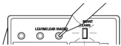
1
Flashes slowly.
- If there is no operation for about 30 seconds after the MACRO button is pressed, the TRANSMIT/LEARN indicator flashes rapidly and the mode before you pressed the MACRO button is restored. Press the MACRO button again.
2
Press a preset macro key on which you want to make a new macro.

Lights up.
- If a key other than a preset macro key is pressed, the TRANSMIT/LEARN indicator flashes rapidly and the current mode is canceled. Repeat this step.
Press a key whose function you want to store as the first function of the new macro.

3
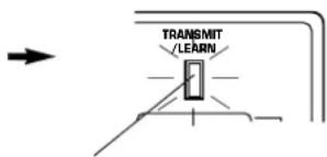
Goes off. (When learning is finished, this indicator lights up again.)
- If a key whose function cannot be stored as a command of macro is pressed, the TRANSMIT/LEARN indicator flashes rapidly and the current mode is canceled. Repeat this step.
- If about 30 seconds pass before a key is pressed, the TRANSMIT/LEARN indicator flashes rapidly and the mode before you began learning operations is restored. Restart from step 1.
4
Repeat step 3 to store the second, the third and more functions. You can store up to seven key functions in series as a macro.
- If the seventh key function has been learned, the TRANSMIT/LEARN indicator flashes rapidly and the mode before you began learning operations is restored. (This shows that the key has completed learning a series of functions as a macro.) You do not have to follow the next step.
When you finish learning, press the MACRO button.
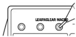
5
Notes
- If, for example, you store a function whose operation takes a long time as the first command, add a command which has no function between the first command and the second command, or repeat the second command again.
- If you program the power on/off switching function of TV, VCR, etc. as a part of a macro sequence, note that it switches the current mode to the other ("on" to "off", or "off" to "on").
For example, when you press the macro key, if the power of TV, VCR, etc. is already on, the power will be turned off even though you may not want it to do so.
Clearing learned functions
To Clear a Learned Function To Clear All Learned Functions
1 To clear a learned key function, press the LEARN button using a ball-point pen or similar object. To clear a macro you made, press the MACRO button.
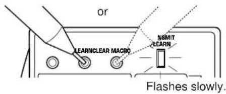
2 Press and hold the CLEAR button using a ball-point pen or similar object.
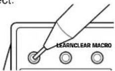
3 Holding the CLEAR button pressed, press and hold the key whose function you want to clear until the indicator flashes 3 times.
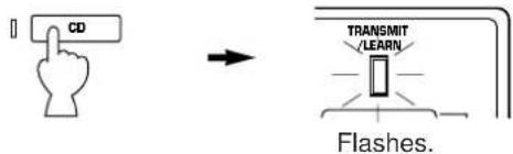
To clear two or more functions sequentially, do not release the CLEAR button, and repeat this step.
Note
If you clear a learned function of a key, the key is restored by the originally preset function. (except the keys which are originally preset with no function.)
1 Select the kind of key functions all of which you want to clear by using the MACRO switch on the side panel of the remote controller.

OFF: Select this position if you want to clear all of the learned functions except macros.
QUICK: Select this position if you want to clear all of the macros you made.
SLOW: Select this position if you want to clear all of the learned functions including macros.
2 Press the CLEAR button using a ball-point pen or similar object.
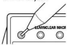
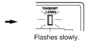
-
If one of the following is made after you press the CLEAR button, the TRANSMIT/LEARN indicator flashes rapidly and the current mode is canceled. Press the CLEAR button again.
-
MACRO switch is switched to another position.
- Another key is pressed.
- There is no operation for about 30 seconds.
3 Press and hold the CLEAR button again. While holding down the CLEAR button, press and hold the MASTER VOLUME and keys simultaneously until the indicator flashes 7 times.
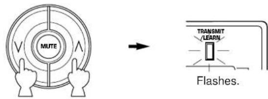
TROUBLESHOOTING
Refer to the chart below when this unit does not function properly. If the problem you are experiencing is not listed below or if the instruction below does not help, disconnect the power cord and contact your authorized YAMAHA dealer or service center.
General
| Problem | Cause | What to Do |
| The unit fails to turn on when the STANDBY/ON switch is pressed, or turns into the standby mode suddenly soon after the power is turned on. | Power cord is not plugged in or is not completely inserted. | Firmly plug in the power cord. |
| The IMPEDANCE SELECTOR switch on the rear panel is not set to either end. | Set the switch to either end when this unit is in the standby mode. | |
| This unit does not work normally. | There is an influence of strong external noise (lightning, excessive static electricity, etc.) or a misoperation on this unit while using this unit. | Turn this unit into the standby mode and disconnect the AC power cord from the AC outlet. After about 30 seconds have passed, connect the power and operate this unit again. |
| No sound or no picture. | Incorrect output cord connections. | Connect the cords properly. If the problem persists, the cords may be defective. |
| Appropriate input source is not selected. | Select the appropriate input source with the INPUT SELECTOR or the EXT. DECODER button. | |
| Speaker connections are not secure. | Secure the connections. | |
| Digital signals other than PCM audio and Dolby Digital (or DTS) encoded signals which this unit cannot reproduce are input to this unit by playing a CD-ROM etc. | Play a source whose signals this unit can reproduce. | |
| No picture | There is no S video terminal connection between this unit and the TV, though S video signals are input to this unit. | Connect this unit's SVIDEO MONITOR OUT terminal to the TV's S video input terminal. |
| The sound suddenly goes off. | The protection circuit has been activated because of short circuit etc. | Turn this unit into the standby mode, and then turn on to reset the protection circuit. |
| The SLEEP timer came on. | Cancel the SLEEP timer function. | |
| Only one side speaker outputs the sound. | Incorrect setting of the BALANCE control. | Adjust it to the appropriate position. |
| Incorrect cord connections. | Connect the cords properly. If the problem persists, the cords may be defective. | |
| No sound from the effect speakers. | The EFFECT button is set off. | Press the EFFECT button to turn it on. |
| A Dolby Surround (or DTS) decoding program is being used with material not encoded with Dolby Surround (or DTS). | Use a different sound field program. | |
| No sound from the front effect speakers. | The function "1E. SYS. SETUP" in the SET MENU mode is set to the "5ch" position. | Set to the "7ch" position. |
| PRO LOGIC/Normal, DOLBY DIGITAL/Normal or DTS DIGITAL SUR./Normal of the DSP program No. 12 is selected. | Select another program (or subprogram). | |
| No sound from the center speaker. | The function "1A. CENTER SP" in the SET MENU mode is set to the "NONE" position. | Select the appropriate position. |
| One of the DSP programs No. 1 to No. 7 is selected when the input signal of source is 2-channel stereo (analog/PCM). | Select another program. | |
| The input signals of source encoded with Dolby Digital or DTS do not have center channel signals. | Refer to the instructions for the source currently played. | |
| Poor bass reproduction. | The function "1D. LFE/BASS OUT" in the SET MENU mode is set in the SW or BOTH position, though your system does not include a subwoofer. | Select the MAIN position. |
| Output mode selection for each channel (MAIN, CENTER or REAR) is improper. | Make output mode selections suitable for your speaker system. | |
| Sound "hums". | Incorrect cord connections. | Firmly connect the audio plugs. If the problem persists, the cords may be defective. |
| No connection from the turntable to the GND terminal. | Make the GND connection between the turntable and this unit. | |
| The volume level is low while playing a record. | The record is being played on a turntable with an MC cartridge. | The player should be connected to the unit through the MC head amplifier. |
| The volume level cannot be increased, or sound is distorted. | The component connected to the TAPE/MD OUT terminals of this unit is turned off. | Turn on the power to the component. |
| DSP parameters and some other settings on this unit cannot be changed. | The function "6. MEMORY GUARD" in the SET MENU mode is set to the "ON" position. | Set to the "OFF" position. |
| "INPUT DATA ERR" appears on the display and no sound is heard. | A nonstandardized source is played back, or the unit playing back a source is misoperating. | Check the source, or turn off the unit playing back the source and then turn on again. |
| The sound field cannot be recorded. | It is not possible to record the sound field on a tape deck connected to this unit's TAPE/MD OUT terminals. | |
| This unit does not operate properly. | The internal microcomputer has been frozen by an external electric shock (lightning, excessive static electricity, etc.) or power supply with low voltage. | Unplug the AC power cord from the wall AC outlet, and then plug in again after about one minute. |
| A source cannot be recorded by a tape deck or VCR connected to this unit. | The source unit is connected to this unit between digital terminals only. | Make additional connection between analog terminals. |
| Noise from nearby TV or tuner. | This unit is too close to the affected equipment. | Move the unit further away from the affected equipment. |
| The sound is degraded when listening with the headphones connected to the compact disc player or tape deck that is connected with this unit. | This unit is in the standby mode. | Turn the power to this unit on. |
Remote controller
| Problem | Cause | What to Do |
| The remote controller does not work. | The batteries of this remote controller are weak. | Replace the batteries with new ones and press the RESET button on the remote controller. |
| The internal microcomputer "freezes". | Press the RESET button on the remote controller. | |
| The remote controller does not function properly. | Wrong distance or angle. | The remote controller will function from a maximum range of 6 meters, no more than 30 degrees off-axis from the front panel. |
| Direct sunlight or lighting (of an inverter type of fluorescent lamp etc.) is striking the remote control sensor of the main unit. | Change position of the main unit. | |
| The internal microcomputer "freezes". | Press the RESET button on the remote controller. | |
| Learning cannot be made successfully. (The TRANSMIT/LEARN indicator does not light up or flash.) | The batteries of this remote controller and/or the other remote controller are weak. | Replace the batteries (and press the RESET button for this remote controller). |
| The distance between the two remote controllers is too far or short. | Place the remote controllers at the proper distance. | |
| The signal coding or modulation of the other remote controller is not compatible with this remote controller. | Learning is not possible. | |
| Memory capacity is full. | Further learning is not possible without deleting unnecessary commands. | |
| The internal microcomputer "freezes". | Press the RESET button on the remote controller. | |
| Continuous functions such as volume are learned, but operate only for a moment before stopping. | Learning process incomplete. | Be sure to press and hold the function key on the other remote controller until the TRANSMIT/LEARN indicator begins flashing slowly. |
When playing back a source encoded with DTS:
| Problem | Cause | What to Do |
| A loud hissing noise is heard when you play back a source encoded with DTS. | The player which plays back the source is not connected to a digital audio signal input terminal of this unit. | The player must be connected to a digital audio signal input terminal of this unit besides analog audio signal terminal connections. |
| The “ANALOG” input mode is selected on this unit. | Select a proper input mode on this unit to turn on the DTS decoder built into this unit. | |
| A percussive noise is heard when you begin playing back a source encoded with DTS. | If the “AUTO” input mode is selected, depending on some sources, there may be a case that a noise is heard while this unit is identifying the format of input signal. | Set the input mode of the currently selected input source to “DTS”. |
| No sound is heard when you play back a source encoded with DTS, even though the “AUTO” or “DTS” input mode is selected on this unit. | The DTS decoder built into this unit does not function because the player has a digital volume control and it is set at a position other than “maximum”, “neutral” or “ineffective”. | Set the player's digital volume control at the maximum, neutral or ineffective position. |
| No sound is heard when you play back an MD onto which you have recorded a source encoded with DTS. | A source encoded with DTS cannot be recorded onto an MD. | |
| No sound is heard when you play back a DAT onto which you have recorded a source encoded with DTS. | Depending on a DAT deck, a source encoded with DTS cannot be recorded onto a DAT. | |
| No sound is heard when you play back a source (CD etc.) even though the currently selected input mode is “AUTO”. | In the “AUTO” mode, DTS-decoding mode cannot be changed to the normal (PCM) digital signal input mode automatically. | Press the INPUT MODE button on the front panel or the input selector button (for the currently selected source) on the remote controller so that “PCM” appears on the display. |
Notes
- It is necessary to use a DTS decoder to play back a source encoded with DTS, so the player which plays back a source must be connected to a digital audio input terminal of this unit in the way described in this manual. If this connection is not made or only a D-to-A converter is used without using a DTS decoder, when you play back a source, only a loud hiss noise will be heard.
- If you make a search (or skip etc.) operation while playing back a source encoded with DTS, the "dts" indicator goes out from the display. This is because this unit automatically changes the DTS-decoding mode to the standard (PCM) digital signal input mode to prevent a noise from being output.
- A source encoded with DTS cannot be recorded onto analog audio and video tapes, and also, an analog tape recorded with a source encoded with DTS cannot be played back.
The same result is obtained for MDs and DATs (depending on a DAT deck used for recording and/or playback).
SPECIFICATIONS
AUDIO SECTION
Minimum RMS Output Power Per Channel
(When both channels are driven)
MAIN L/R (20 Hz to 20 kHz, 0.02% THD, 8 ohms)
100W+100W
CENTER (20 Hz to 20 kHz, 0.02% THD, 8 ohms)
100W
REAR L/R (20 Hz to 20 kHz, 0.02% THD, 8 ohms)
100W+100W
FRONT L/R (1 kHz, 0.05% THD, 8 ohms)
25W+25W
Maximum Power [China and General models only]
1 kHz, 10% THD, 8 ohms (When both channels are driven)
MAIN L/R .135W+135W
CENTER .135W
REAR L/R .135W+135W
FRONT L/R .35W+35W
Dynamic Power Per Channel
(by IHF Dynamic Headroom Measuring Method) [China and General models only] MAIN L/R (8 ohms/6 ohms/4 ohms/2 ohms) (When both channels are driven) 140W/170W/220W/320W
Dynamic Headroom [China and General models only]
MAIN L/R (8 ohms) 1.46 dB
DIN Standard Output Power Per Channel [Europe and U.K. models only] MAIN L/R (1 kHz, 0.7% THD, 4 ohms) (When both channels are driven). 160W
IEC Power [Europe and U.K. models only]
MAIN L/R (1 kHz, 0.015% THD, 8 ohms)
(When both channels are driven) 115W
Power Band Width (20 Hz to 20 kHz)
8 ohms, 50W, 0.08% THD
(When both channels are driven) 10 Hz to 50 kHz
Damping Factor MAIN L/R (20 Hz to 20 kHz, 8 ohms) 200 or more
Input Sensitivity/Impedance (100W/8 ohms)
CD/TAPE-MD/DVD-LD/TV-DBS/VCR 1/VCR 2/VIDEO AUX
150 mV/47 k-ohms
PHONO MM. 2.5 mV/47 k-ohms
MAIN IN 1V/47 k-ohms
Maximum Input Signal (1 kHz, 0.05% THD)
CD/TAPE-MD/DVD-LD/TV-DBS/VCR 1/VCR 2/VIDEO AUX
(EFFECT ON) 2.3V
PHONO MM 110 mV
Output Level/Impedance
REC OUT 150 mV/1.0 k-ohms
PRE OUT
MAIN, CENTER, REAR, FRONT 1.0V/1.5 k-ohms
SUBWOOFER (MAIN SP: SMALL)
(EFFECT OFF) 4.0V/1.5 k-ohms
Maximum Voltage Output (20 Hz to 20 kHz, 1% THD) PRE OUT (MAIN L/R).3V or more
Headphone Jack Rated Output/Impedance
Output Level
CD/TAPE-MD/DVD-LD/TV-DBS/VCR 1/VCR 2/VIDEO AUX
Input: 1 kHz, 150 mV, RL=8 ohms 0.5V
Impedance 440 ohms
Frequency Response (20 Hz to 20 kHz) CD/TAPE-MD/DVD-LD/TV-DBS/VCR 1/VCR 2/VIDEO AUX to MAIN L/R SP OUT 0±0.5 dB
RIAA Equalization Deviation (20 Hz to 20 kHz)
PHONO MM. 0±0.5 dB
Total Harmonic Distortion (20 Hz to 20 kHz) CD/TAPE-MD/DVD-LD/TV-DBS/VCR 1/VCR 2/VIDEO AUX to PRE OUT (MAIN L/R), 1V. 0.005% or less CD/TAPE-MD/DVD-LD/TV-DBS/VCR 1/VCR 2/VIDEO AUX to SP OUT (MAIN L/R), 50W/8 ohms. 0.015% or less PHONO MM to REC OUT, 3V. 0.01% or less MAIN IN to SP OUT (MAIN L/R, CENTER), 50W/8 ohms. 0.008% or less
Signal-to-Noise Ratio (IHF-A Network) CD/TAPE-MD/DVD-LD/TV-DBS/VCR 1/VCR 2/VIDEO AUX (Input Shorted) (EFFECT OFF) .96 dB or more PHONO MM (Input Shorted 5mV (EFFECT OFF) [U.K, China and General models] .86 dB or more [Europe model]. .82 dB or more
Residual Noise (IHF-A Network) MAIN L/R SP OUT. 170 V or less
Channel Separation (Vol. -30 dB)
CD/TAPE-MD/DVD-LD/TV-DBS/VCR 1/VCR 2/VIDEO AUX
Input 5.1 k-ohms Shorted (EFFECT OFF)
1 kHz/10 kHz .60 dB/45 dB or more
PHONO MM Input Shorted (EFFECT OFF)
1 kHz/10 kHz .60 dB/55 dB or more
Tone Control Characteristics
Bass
Boost/Cut 350 Hz
Turnover frequency 350 Hz
Treble
Boost/Cut 3.5 kHz
Turnover frequency
Bass Extension (MAIN L/R) +6 dB (50 Hz)
Filter Characteristics
MAIN L/R, CENTER, REAR L/R
(MAIN, CENTER, REAR SP: SMALL) (H.P.F.)
fc = 90 Hz, 12 dB/oct.
SUBWOOFER (L.P.F.) ... fc = 90 Hz, 18 dB/oct.
Gain Tracking Error (0 to -60 dB)
MAIN L/R .3 dB or less
Audio Muting
VIDEO SECTION
Video Signal Type
[Europe and U.K. models] PAL
[China and General models] NTSC/PAL
Video Signal Level 1 Vp-p/75 ohms
S-Video Signal Level
Y 1 Vp-p/75 ohms
C 0.286 Vp-p/75 ohms
Maximum Input Level 1.5 Vp-p or more
Signal-to-Noise Ratio 50 dB or more
Monitor Out Frequency Response ....... 5 Hz to 10 MHz, -3 dB
GENERAL
Power Supply
[Europe and U.K. models] AC 230V, 50 Hz
[China and General models] AC 110/120/220/240V, 50/60 Hz
Power Consumption 480W
Maximum Power Consumption
[General model only] 770W
AC Outlets
3 SWITCHED OUTLETS
[Europe, China and General models] 100W max. total
1 SWITCHED OUTLET
[U.K.model] 100W max.
[China and General models (without side panels)] 435 x 171 x 470 mm (17-1/8" x 6-3/4" x 18-1/2")
[China and General models (with side panels)] 473 x 171.5 x 470 mm (18-5/8" x 6-3/4" x 18-1/2")
Weight
[Europe and U.K. models] 19.5 kg (42.9 lbs.)
[China and General models (without side panels)] 19.5 kg (42.9 lbs.)
[China and General models (with side panels)] 21.0 kg (46.2 lbs.)
Accessories .Remote controller Batteries User function stickers AM loop antenna Indoor FM antenna
Felicitations!
Prises CA [AC OUTLET(S) (SWITCHED)]
1A. CENTER SP
1B. REAR SP
1C. MAIN SP
1D. LFE/BASS OUT
1E. SYS. SETUP
1F. MAIN LEVEL
1A. CENTER SP
1B. REAR SP
1C. MAIN SP
1D. LFE/BASS OUT
1E. SYS. SETUP
1F. MAIN LEVEL
2. DLBY DGTL SET
2A. LFE LEVEL
2B. D-RANGE
3. DTS SET
3A. LFE LEVEL
4. CENTER DELAY
- PARAMETER INI
- MEMORY GUARD
- TV/DBS INPUT
- DIMMER
→ Europe Hall A
INIT. DELAY·29ms
ROOM SIZE···1.0
LIVENESS···5
Sousprogramme
S. INIT. DLY (retard initial du champ sonore surround)
S. DELAY (retard surround)
MAIN L/R (8 ohms/6 ohms/4 ohms/2 ohms)
CD/TAPE-MD/DVD-LD/TV-DBS/VCR 1
/VCR 2/VIDEO AUX 150 mV/47 k-ohms
PHONO MM 2,5 mV/47 k-ohms
MAIN IN 1V/47 k-ohms
CD/TAPE-MD/DVD-LD/TV-DBS/VCR 1
/VCR 2/VIDEO AUX (EFFECT ON) 2,3V
PHONO MM 110 mV
CD/TAPE-MD/DVD-LD/TV-DBS/VCR 1/VCR 2
VIDEO AUX a MAIN L/R SP OUT 0±0,5 dB
CD/TAPE-MD/DVD-LD/TV-DBS/VCR 1/VCR 2
CD/TAPE-MD/DVD-LD/TV-DBS/VCR 1/VCR 2
/VIDEO AUX (Entree court-circuitee) (EFFECT OFF)
96 dB ou plus
PHONO MM (Entree court-circuitee 5mV (EFFECT OFF)
Accentuation/Coupure 10 dB (50 Hz)
Accentuation/Coupure 10 dB (20 kHz)
MAIN L/R, CENTER, REAR L/R
(MAIN, CENTER, REAR SP: SMALL) (H.P.F)
fc=90Hz,12dB/occt.
SUBWOOFER (L.P.F.) . fc = 90 Hz,18 dB/oct .
Dimensions (L x H x P)
DTS Digital Surround
CINEMA DSP: Dolby Surround + DSP / DTS + DSP
1A. CENTER SP
1B. REAR SP
1C. MAIN SP
1D. LFE/BASS OUT
1E. SYS. SETUP
1F. MAIN LEVEL
1A. CENTER SP
1B. REAR SP
1C. MAIN SP
1D. LFE/BASS OUT
1E. SYS. SETUP
1F. MAIN LEVEL
2. DLBY DGTL SET
2A. LFE LEVEL
2B. D-RANGE
- DTS SET
3A. LFE LEVEL
-
CENTER DELAY
-
PARAMETER INI
- MEMORY GUARD
- TV/DBS INPUT
- DIMMER
S. ROOM SIZE (SurroundraumgroBe)
Lautstärketasten (MASTER VOLUME und)
FRONT L/R (1 kHz, 0.05% Klirrgrad, 8 Ohm) ....25W+25W
MAIN L/R (8 Ohm/6 Ohm/4 Ohm/2 Ohm)
MAIN L/R (1 kHz, 0,015% Kllrgrad, 8 Ohm)
SUBWOOFER (MAIN SP: SMALL) (EFFECT OFF)
4,0V/1,5 k Ohm
(Eingang CD/TAPE-MD/DVD-LD/TV-DBS/VCR 1/VCR
2/VIDEO AUX: 1 kHz, 150 mV, RL=8 Ohm) 0.5V
Impedanz 440 Ohm
Ubergangsfrequency 350 Hz
Hohen
Pegelumfang 10 dB (20 kHz)
Ubergangsfrequency 3,5 kHz
Baβ-Extension (MAIN L/R) +6 dB (50 Hz)
Filtercharakteristik
MAIN L/R, CENTER, REAR L/R
(MAIN, CENTER, REAR SP: SMALL) (H.P.F.)
fc = 90 Hz, 12 dB/Oktave
SUBWOOFER (L.P.F.) .90 Hz, 18 dB/Oktave
DTS Digital Surround
CINEMA DSP: Dolby Surround + DSP / DTS + DSP
1A. CENTER SP
1B. REAR SP
1C. MAIN SP
1D. LFE/BASS OUT
1E. SYS. SETUP
1F. MAIN LEVEL

BASS TONE EXTENSION BYPASS

ON OFF

BASS TONE EXTENSION BYPASS

ON OFF
1A. CENTER SP
1B. REAR SP
1C. MAIN SP
1D. LFE/BASS OUT
1E. SYS. SETUP
1F. MAIN LEVEL
2. DLBY DGTL SET
2A. LFE LEVEL
2B. D-RANGE
- DTS SET
3A. LFE LEVEL
-
CENTER DELAY
-
PARAMETER INI
- MEMORY GUARD
- TV/DBS INPUT
- DIMMER
Standardvardet ar 1,0.
S. INIT. DLY (Initial surroundforderjning)
PRE OUT (MAIN L/R). 3V erer mer
Markuteffekt/impedans, hörlursuttag
Utniva (CD/TAPE·MD/DVD·LD/TV·DBS/VCR 1/VCR 2/VIDEO AUX Ingang: 1 kHz, 150 mV, RL=8 ohm) 0,5V
Impedans 440 ohm
Frekvensomfang (20 Hz till 20 kHz)
CD/TAPE-MD/DVD-LD/TV-DBS/VCR 1/VCR 2/VIDEO AUX till MAIN L/R, SP OUT 0± 0,5 dB
MAIN L/R, CENTER, REAR L/R
(MAIN, CENTER, REAR SP: SMALL) (H.P.F.)
fc = 90 Hz, 12 dB/oct.
SUBWOOFER (L.P.F.) fc = 90 Hz, 18 dB/oct.
1A. CENTER SP
1B. REAR SP
1C. MAIN SP
1D. LFE/BASS OUT
1E. SYS. SETUP
1F. MAIN LEVEL
1A. CENTER SP
1B. REAR SP
1C. MAIN SP
1D. LFE/BASS OUT
1E. SYS. SETUP
1F. MAIN LEVEL
2. DLBY DGTL SET
2A. LFE LEVEL
2B. D-RANGE
3. DTS SET
3A. LFE LEVEL
4. CENTER DELAY
- PARAMETER INI
- MEMORY GUARD
- TV/DBS INPUT
- DIMMER
da 1,0 a 5,0 secondi
MAIN L/R, CENTER, REAR L/R
(MAIN, CENTER, REAR SP: SMALL) (H.P.F.).fc = 90 Hz, 12
dB/occt. SUBWOOFER (L.P.F.). fc = 90Hz 18 dB/occt.
Dimensioni (L x A x P)
[Modello per l'Europa e la Gran Bretagna] 435 x 171 x 470 mm
this experience is a great way to discover the world of art and culture. It's also a great way to learn about the history of art and culture. This is a great opportunity for you to explore the history of art and culture in Spain, including the medieval period, the Renaissance, modernism, and today's art scene.
1A. CENTER SP
1B. REAR SP
1C. MAIN SP
1D. LFE/BASS OUT
1E. SYS. SETUP
1F. MAIN LEVEL
BASS TONE EXTENSION BYPASS

6
Ajustar a "OFF (
Ajuste el interruptor PARAMETER/SET MENU en el control remoto a la posicion PARAMETER.
Control remoto
7
BASS TONE EXTENSION BYPASS


ON OFF
Paraajustar los controles BASS y TREBLE

BASS TREBLE

BASS TONE EXTENSION BYPASS


ON OFF
No. 12 (Normal): principal, central,trasero
No. 12 (Enhanced): principal, central,trasero,efecto delantero
1A. CENTER SP
1B. REAR SP
1C. MAIN SP
1D. LFE/BASS OUT
1E. SYS. SETUP
1F. MAIN LEVEL
2. DLBY DGTL SET
2A. LFE LEVEL
2B. D-RANGE
3. DTS SET
3A. LFE LEVEL
4. CENTER DELAY
- PARAMETER INI
- MEMORY GUARD
- TV/DBS INPUT
- DIMMER
MAIN, CENTER, REAR, FRONT 1.0V/1.5 k-ohmios
SUBWOOFER (MAIN SP: SMALL) (EFFECT OFF) 4.0V/1.5 k-ohmios
Salida de voltaje maxima (20 Hz a 20 kHz, 1% de D.A.T.)
PRE OUT (MAIN L/R) 3V o mas
CD/TAPE-MD/DVD-LD/TV-DBS/VCR 1/VCR 2/VIDEO AUX a PRE OUT (MAIN L/R), 1V0,005% o menos
CD/TAPE-MD/DVD-LD/TV-DBS/VCR 1/VCR 2/VIDEO AUX a SP OUT (MAIN L/R), 50W/8 ohmios .0,015% o menos PHONO MM a REC OUT, 3V .0,01% o menos MAIN IN a SP OUT (MAIN L/R, CENTER), 50W/8 ohmios .0,008% o menos
MAIN L/R, CENTER, REAR L/R
(MAIN, CENTER, REAR SP: SMALL) (H.P.F.)
fc=90Hz,12dB/occt.
SUBWOOFER (L.P.F.) f_c = 90 Hz , 18 dB/oct.
DTS Digital Surround
CINEMA DSP: Dolby Surround + DSP / DTS + DSP
(3 SWITCHED OUTLETS)
1A. CENTER SP
1B. REAR SP
1C. MAIN SP
1D. LFE/BASS OUT
1E. SYS. SETUP
1F. MAIN LEVEL
1A. CENTER SP
1B. REAR SP
1C. MAIN SP
1D. LFE/BASS OUT
1E. SYS. SETUP
1F. MAIN LEVEL
2. DLBY DGTL SET
2A. LFE LEVEL
2B. D-RANGE
- DTS SET
3A. LFE LEVEL
-
CENTER DELAY
-
PARAMETER INI
- MEMORY GUARD
- TV/DBS INPUT
- DIMMER
Standaard instelling is 1,0.
S. LIVENESS (surround live)
MAIN L/R, CENTER, REAR L/R
(MAIN, CENTER, REAR SP: SMALL) (H.P.F.)
fc=90Hz,12dB/occt.
SUBWOOFER (L.P.F.). fc = 90 Hz,18 dB/oct .


