
DSPA595 - Home cinema amp YAMAHA - Free user manual and instructions
Find the device manual for free DSPA595 YAMAHA in PDF.
User questions about DSPA595 YAMAHA
0 question about this device. Answer the ones you know or ask your own.
Ask a new question about this device
Download the instructions for your Home cinema amp in PDF format for free! Find your manual DSPA595 - YAMAHA and take your electronic device back in hand. On this page are published all the documents necessary for the use of your device. DSPA595 by YAMAHA.
USER MANUAL DSPA595 YAMAHA
Main: 65 W + 65 W (8Ω) RMS Output
Power, 0.04% THD, 20 Hz - 20 kHz
Center: 65 W (8Ω) RMS Output
Power, 0.04% THD, 20 Hz - 20 kHz
Rear: 65 W + 65 W (8Ω) RMS Output
Power, 0.04% THD, 20 Hz - 20 kHz
- Digital Sound Field Processor
- Dolby Digital Decoder
- Dolby Pro Logic Surround Decoder
CINEMA DSP: Theater-like Sound
Experience by the Combination of Dolby Surround and YAMAHA DSP Technology
- 6-Channel External Decoder Input for DTS and other future formats
Automatic Input Balance Control for Dolby Pro Logic Surround
- Test Tone Generator for Easier Speaker Balance Adjustment
- Speaker Output Mode Changing Capability
Video Signal Input/Output Capability (Including S Video Connections)
- SLEEP Timer
Universal Remote Control Transmitter with Preset Manufacturer Codes
CONTENTS
SUPPLIED ACCESSORIES 2
FEATURES 3
CAUTION 4
- Introduction
FEATURES ON SOUND EFFECT. 5
CONTROLS AND THEIR FUNCTIONS 7
Preparation
SPEAKER SETUP 10
CONNECTIONS 12
ADJUSTMENTS
BEFORE USING THIS UNIT 19
Basic Operation
BASIC OPERATIONS 24
SETTING THE SLEEP TIMER 28
Information about DSP
USING DIGITAL SOUND FIELD
PROCESSOR (DSP) 29
Advanced Information
ADJUSTMENTS
IN THE "SET MENU" MODE 35
Remote Control Transmitter
REMOTE CONTROL TRANSMITTER 37
SETUP CODES 42
NOTES ABOUT THE REMOTE CONTROL TRANSMITTER 43
TROUBLESHOOTING 44
SPECIFICATIONS 46
LIST OF MANUFACTURER'S CODE 311
CAUTION : READ THIS BEFORE OPERATING YOUR UNIT.
- To assure the finest performance, please read this manual carefully. Keep it in a safe place for future reference.
- Install this unit in a cool, dry, clean place - away from windows, heat sources, sources of excessive vibration, dust, moisture and cold. Avoid sources of humming (transformers, motors). To prevent fire or electrical shock, do not expose the unit to rain or water.
- Never open the cabinet. If something drops into the set, contact your dealer.
- Do not use force on switches, controls or connection wires. When moving the unit, first disconnect the power plug and the wires connected to other equipment. Never pull the wires themselves.
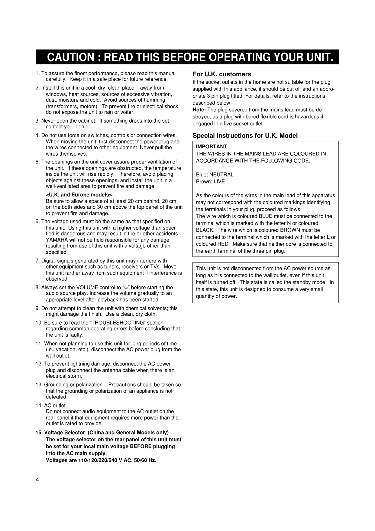
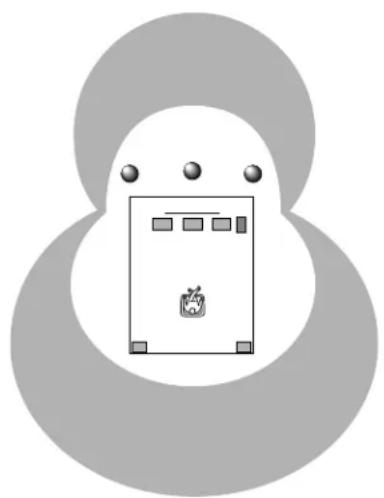
- The openings on the unit cover assure proper ventilation of the unit. If these openings are obstructed, the temperature inside the unit will rise rapidly. Therefore, avoid placing objects against these openings, and install the unit in a well-ventilated area to prevent fire and damage.
Be sure to allow a space of at least 20cm behind, 20cm on the both sides and 30cm above the top panel of the unit to prevent fire and damage.
- The voltage used must be the same as that specified on this unit. Using this unit with a higher voltage than specified is dangerous and may result in fire or other accidents. YAMAHA will not be held responsible for any damage resulting from use of this unit with a voltage other than specified.
- Digital signals generated by this unit may interfere with other equipment such as tuners, receivers or TVs. Move this unit farther away from such equipment if interference is observed.
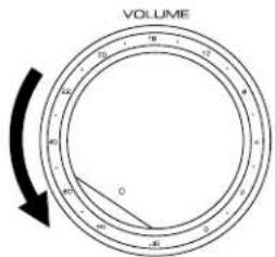
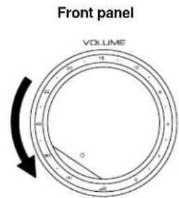
- Always set the VOLUME control to " 心 before starting the audio source play. Increase the volume gradually to an appropriate level after playback has been started.
- Do not attempt to clean the unit with chemical solvents; this might damage the finish. Use a clean, dry cloth.
- Be sure to read the "TROUBLESHOOTING" section regarding common operating errors before concluding that the unit is faulty.
- When not planning to use this unit for long periods of time (ie., vacation, etc.), disconnect the AC power plug from the wall outlet.
- To prevent lightning damage, disconnect the AC power plug and disconnect the antenna cable when there is an electrical storm.
- Grounding or polarization - Precautions should be taken so that the grounding or polarization of an appliance is not defeated.
- AC outlet Do not connect audio equipment to the AC outlet on the rear panel if that equipment requires more power than the outlet is rated to provide.
- Voltage Selector (China and General Models only) The voltage selector on the rear panel of this unit must be set for your local main voltage BEFORE plugging into the AC main supply. Voltages are 110/120/220/240 V AC, 50/60 Hz.
For U.K. customers
If the socket outlets in the home are not suitable for the plug supplied with this appliance, it should be cut off and an appropriate 3 pin plug fitted. For details, refer to the instructions described below.
Note: The plug severed from the mains lead must be destroyed, as a plug with bared flexible cord is hazardous if engaged in a live socket outlet.
Special Instructions for U.K. Model
IMPORTANT
THE WIRES IN THE MAINS LEAD ARE COLOURED IN ACCORDANCE WITH THE FOLLOWING CODE:
Blue: NEUTRAL
Brown: LIVE
As the colours of the wires in the main lead of this apparatus may not correspond with the coloured markings identifying the terminals in your plug, proceed as follows:
The wire which is coloured BLUE must be connected to the terminal which is marked with the letter N or coloured BLACK. The wire which is coloured BROWN must be connected to the terminal which is marked with the letter L or coloured RED. Make sure that neither core is connected to the earth terminal of the three pin plug.
This unit is not disconnected from the AC power source as long as it is connected to the wall outlet, even if this unit itself is turned off. This state is called the standby mode. In this state, this unit is designed to consume a very small quantity of power.
FEATURES ON SOUND EFFECT
This unit incorporates a sophisticated, multi-program digital sound field processor. The processor allows you to electronically expand and change the shape of the audio sound field from both audio and video sources, creating a theater-like experience in your listening room. This unit has a total of 8 digital sound field processor (DSP) modes. You can create an excellent audio sound field by selecting a suitable sound field (this will, of course, depend on what you will be listening to), and adding desired adjustments.
Digital Sound Field Processing
What is it that makes live music so good? Today's advanced sound reproduction technology lets you get extremely close to the sound of a live performance, but chances are you'll still notice something missing, the acoustic environment of the live concert hall. Extensive research into the exact nature of the sonic reflections that create the ambience of a large hall has made it possible for YAMAHA engineers to bring you this same sound in your listening room, so you'll feel all the sound of a live concert.
Dolby Pro Logic Surround
This unit employs a Dolby Pro Logic Surround decoder similar to professional Dolby Stereo decoders used in many movie theaters. By using the Dolby Pro Logic Surround decoder, you can experience the dramatic realism and impact of Dolby Surround movie theater sound in your own home. Dolby Pro Logic employs a four channel five speaker system. The Pro Logic Surround system divides the input signal into four levels: the left and right main channels, the center channel (used for dialog), and the rear surround sound channels (used for sound effects, background noise, and other ambient noises). The center channel allows listeners seated in even less-than-ideal positions to hear the dialog originating from the action on the screen while experiencing good stereo imaging.
Dolby Digital
The built-in Dolby Digital decoder leads you into a totally new sound experiences.
Dolby Digital is a new generation of multi-channel digital audio technology, or the newest spatial sound processing format developed for 35mm film-movies by employing a new kind of low bit-rate audio coding.
Dolby Digital is a digital surround sound system that provides completely independent multi-channel audio to consumers. In multi-channel form, Dolby Digital provides five full range channels in what is sometimes referred to as a "3/2" configuration: three front channels (left, center and right), plus two surround channels. A sixth bass-only effect channel is also provided for output of LFE (low frequency effect), or low bass effects that are independent of other channels. This channel is counted as 0.1, thus giving rise to the term 5.1 channels in total.
In addition, this unit incorporates a Dolby Pro Logic Surround decoder and Dolby Digital decoder for multi-channel sound reproduction of Dolby Surround encoded video sources. The operation of the Dolby Pro Logic Surround or Dolby Digital decoder can be controlled by selecting a corresponding DSP program including combined operations of the YAMAHA DSP and the Dolby Pro Logic Surround or Dolby Digital decoder.
Furthermore, our technicians, armed with sophisticated measuring equipment, have even made it possible to capture the acoustics of a variety of actual concert halls, theaters, etc. from around the world, to allow you to accurately re-create any one of these live performance environments, all in your home.
Dolby Surround is encoded on the sound track of pre-recorded video tapes, laser discs, and some TV/cable broadcasts. When you play a source encoded with Dolby Surround on this unit, the Dolby Pro Logic Surround decoder decodes the signal and distributes the surround-sound effects.
This Dolby Pro Logic Surround decoder employs a digital signal processing system. This system improves the stability of sound at each channel and crosstalk between channels, so that positioning of sounds around the room is more accurate compared with conventional analog signal processing systems.
In addition, this unit features a built-in automatic input balance control. This always assures you the best performance without manual adjustment.
Compared to Dolby Pro Logic that is referred to a "3/1" system (left front, center, right front and just one surround channel), Dolby Digital features two surround channels, called stereo or split surrounds, each offering the same full range fidelity as the three front channels.
Sound of wide dynamic range reproduced by the five full range channels presents listeners much excitement that has never been experienced before. Precise sound orientation by the discrete digital sound processing expands realism that the original movie possesses.
LD and DVD are home audio formats that could benefit from Dolby Digital. In the near future, Dolby Digital will also be applied to DBS, CATV and HDTV. The ongoing release of Dolby Stereo Digital theatrical films now underway will provide an immediate source of Dolby Digital encoded video software.
Manufactured under license from Dolby Laboratories Licensing Corporation. "Dolby", "Pro Logic", and the double-D symbol are trademarks of Dolby Laboratories Licensing Corporation. Copyright 1992 Dolby Laboratories, Inc. All rights reserved.
The following original functions make the surround-sound effect of Dolby Digital become the most suitable for your audio system and the listening conditions.
- Dynamic range (sound scale) of source can be changed so that it will be suitable for the listening conditions.
- Output of low bass from any channel can be assigned to either the MAIN SPEAKERS terminals or SUBWOOFER terminal to maximize system performance.
Output of LFE can be assigned to either the MAIN SPEAKERS terminals or SUBWOOFER terminal to maximize system performance.
Dolby Surround sound system shows its full ability in a large movie theater, because movie sounds are originally designed to be reproduced in a large movie theater using many speakers. It is difficult to create a sound environment similar to that of a movie theater in your listening room, because the room size, materials of inside walls, the number of speakers, etc. of your listening room is much different from those of a movie theater.
Dolby Pro Logic + 2 Digital Sound Fields
Digital sound fields are created on the presence side and the rear surround side of the Dolby Pro Logic Surround-decoded sound field respectively. They create a wide acoustic environment and emphasize surround-effect in the room, letting you feel much presence as if you are watching a movie in a popular Dolby Stereo theater.
This combination is available when the sound field program DOLBY PRO LOGIC ENHANCED/DOLBY DIGITAL ENHANCED, 70 mm MOVIE THEATER/DIGITAL MOVIE THEATER or TV SPORTS is selected, and the input signal of source is analog, PCM audio or encoded with the Dolby Digital in 2-channel.
YAMAHA DSP technology made it possible to present you with nearly the same sound experience as that of a large movie theater in your listening room by compensating for lack of presence and dynamics in your listening room with its original digital sound fields combined with Dolby Surround sound field.
CINEMADSP
The YAMAHA "CINEMA DSP" logo indicates those programs are created by the combination of Dolby Surround and YAMAHA DSP technology.
Dolby Digital + 3 Digital Sound Fields
Digital sound fields are created on the presence side and the independent left and right surround sides of the Dolby Digital-decoded sound field respectively. They create a wide acoustic environment and much surround effect in the room without losing high channel separation. With wide dynamic range of Dolby Digital sound, this sound field combination lets you feel as if you are watching a movie in the newest Dolby Stereo Digital theater. This will be the most ideal home theater sound at the present time.
This combination is available when the sound field program DOLBY PRO LOGIC ENHANCED/DOLBY DIGITAL ENHANCED, 70 mm MOVIE THEATER/DIGITAL MOVIE THEATER or TV SPORTS is selected, and the input signal of source is encoded with the Dolby Digital (except in 2-channel).
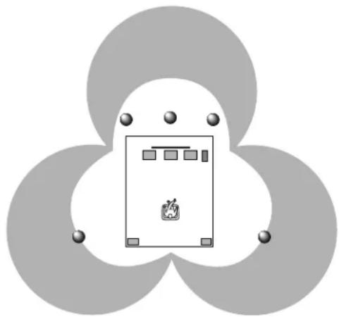
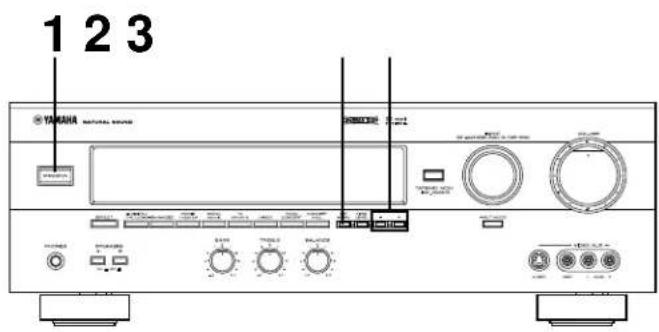
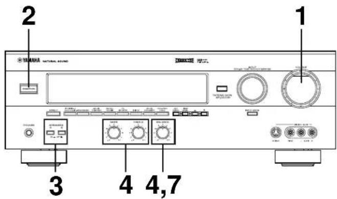
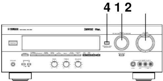
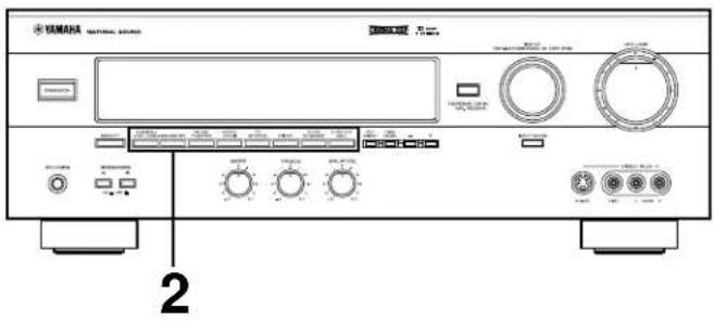
CONTROLS AND THEIR FUNCTIONS
FRONT PANEL
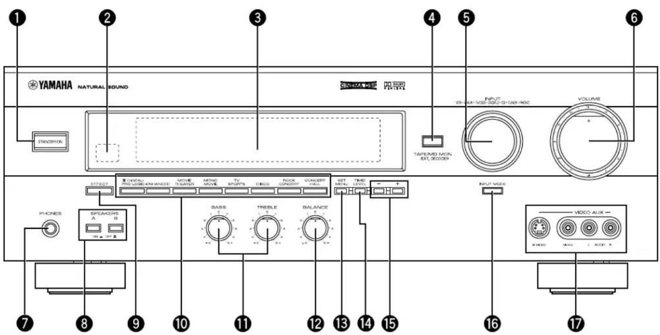
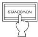
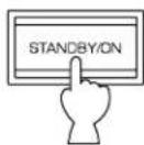
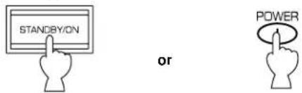
STANDBY/ON
Press this switch to turn the power of this unit on. Press it again to turn this unit into the standby mode.
Standby mode
In this state, this unit consumes a very small quantity of power to receive infrared-signals from the remote control transmitter.
Remote control sensor
Receives signals from the remote control transmitter.
3 Display
Shows various information. (For details, refer to page 9.)
Press this button to play a tape or an MD. The "TAPE/MD MON" indicator lights up on the display.
When you press the button next, the "TAPE/MD MON" indicator goes off and "EXT. DECDR" appears on the display and you can play the signal connected to the EXTERNAL DECODER INPUT terminals.
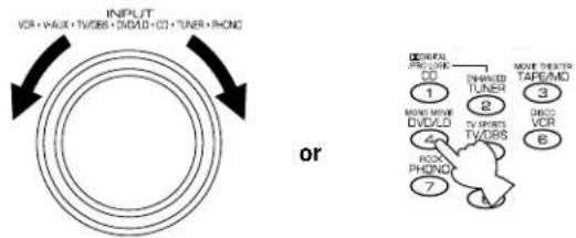
5 INPUT
Turn this selector to select the program source (VCR,VIDEO AUX, TV/DBS, DVD/LD, CD, TUNER, PHONO) to listen to or watch.
The name of the selected program source appears on the display.
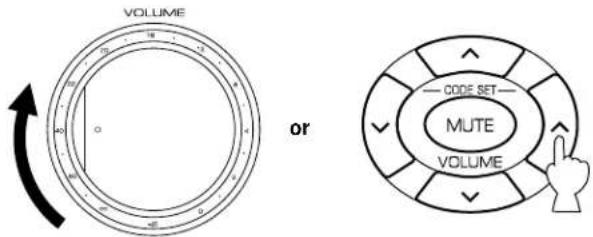
6 VOLUME
This control is used to raise or lower the volume level.
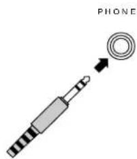
PHONES jack
When you use headphones, connect the headphones to the PHONES jack. You can listen to the sound to be output from the main speakers through headphones.
When using headphones only, set both SPEAKERS A and B to the OFF position and switch off the digital sound field processor (so that no DSP program name appears on the display) by pressing EFFECT.
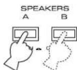
8 SPEAKERS
Set A or B (or both A and B) to the ON position for the main speaker system (connected to this unit) you will use. Set it (or them) for the main speaker system you will not use to the OFF position.
9 EFFECT
Switches on and off the output from the center and rear speakers so that the sound becomes normal 2-channel.
- Even if the output from the center and rear speakers is off, when the Dolby Digital is decoded, the signals at all channels are distributed to the main channels and output from the main speakers.
10 PROGRAM selector
Press these buttons to select the DSP program.
The name of the selected program appears on the display.
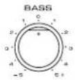
1 Tone controls
These controls are effective only for the sound from the main speakers.
BASS
Used to increase or decrease the low frequency response. The "0" position produces flat response.
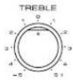
TREBLE
Used to increase or decrease the high frequency response.
The "0" position produces flat response.
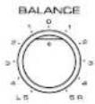
12 BALANCE
This control is effective only for the sound from the main speakers.
Adjusts the balance of the output volume to the left and right speakers to compensate for sound imbalance caused by speaker location or listening room conditions.
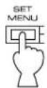
13 SET MENU
Press this button to select functions in the SET MENU mode.
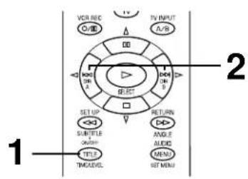
TIME/LEVEL
Press this button to select the setting of delay time or speaker output levels in the TIME/LEVEL mode.
15 +/
These buttons are used to adjust settings of the SET MENU mode and the TIME/LEVEL mode. In the TIME/LEVEL mode, press + to increase delay time or speaker output levels. Press - to decrease delay time or speaker output levels.
16 INPUT MODE
Switches the DVD/LD and TV/DBS input signal mode (AUTO/ANALOG).
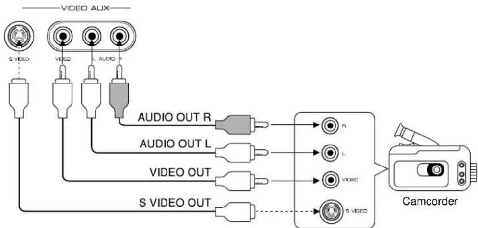
VIDEO AUX terminals
Connect an auxiliary video or audio input source unit such as a camcorder to these terminals. If the connected video unit has a S video output terminal, connect it to the SVIDEO terminal to obtain a high resolution picture. The source connected to these terminals can be selected by INPUT.
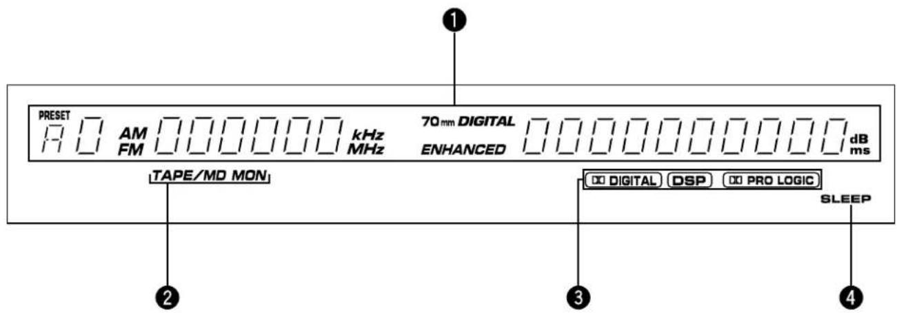

Multi-information display
Displays various information, for example name of selected DSP program and name of selected input source.

TAPE/MD MON indicator
Lights up when the tape deck (or MD recorder etc.) is selected as the input source by pressing TAPE/MD MON / EXT. DECODER on the front panel or TAPE/MD on the remote control transmitter.

Datal indicators
PROLOGIC
"Digital" lights up when the built-in Dolby Digital decoder is on and the signals of selected source encoded with the Dolby Digital is not in 2-channel. "Lights up when the built-in digital sound field processor is on, and "PROLOGIC" lights up when the built-in Dolby Pro Logic Surround decoder is on. Depending on the selected DSP program, both "Digital" DSPboth and DSRill light PROLOGIC

SLEEP indicator
Lights up while the built-in SLEEP timer is functioning.
SPEAKER SETUP
SPEAKERS TO BE USED
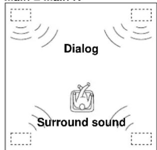
This unit is designed to provide the best sound-field quality with a 5-speaker configuration, using main speakers, rear speakers and a center speaker.
The main speakers are used for the main source sound plus the effect sounds. They will probably be the speakers from your present stereo system. The rear speakers are used for the effect and surround sounds, and the center speaker is for the center sounds (dialog, vocals, etc.). If for some reason it is not practical to use a center speaker, you can do without it. Best results, however, are obtained with the full system.
The main speakers should be high performance models and have enough power handling capacity to accept the maximum output of your audio system.
Other speakers do not have to be equal to the main speakers. For precise sound localization, however, it is ideal to use high performance models that can reproduce sounds in the full range for the center speaker and the rear speakers.
Use of a subwoofer expands your sound field
It is also possible to further expand your system with the addition of a subwoofer and amplifier. The use of a subwoofer is effective not only for reinforcing bass frequencies from any or all channels, but also for reproducing the LFE (low frequency effect) sound with high fidelity when playing back a source with the Dolby Digital decoded. You may wish to choose the convenience of a YAMAHA Active Servo Processing Subwoofer System, which has its own built-in power amplifier.
This configuration is the most effective and recommended one. When playing back a source using the DSP program, DOLBY PRO LOGIC/DOLBY DIGITAL, DOLBY PRO LOGIC ENHANCED/DOLBY DIGITAL ENHANCED, 70 mm MOVIE THEATER/DIGITAL MOVIE THEATER, MONO MOVIE or TV SPORTS, or when playing back a source which contains center-channel signals (dialog, vocals, etc.) using any DSP program with the Dolby Digital decoded, conversations will be output from the center speaker and the ambience will be excellent.
Note: Set the CNTR (CENTER SPEAKER) mode to the "LARGE" or "SMALL" position. (For details, see page 19.)
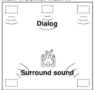
4-Speaker Configuration
The center speaker is not used in this configuration. When playing back a source using the DSP program, DOLBY PRO LOGIC/DOLBY DIGITAL, DOLBY PRO LOGIC ENHANCED/ DOLBY DIGITAL ENHANCED, 70 mm MOVIE THEATER/ DIGITAL MOVIE THEATER, MONO MOVIE or TV SPORTS, or when playing back a source which contains center-channel signals (dialog, vocals, etc.) using any DSP program with the Dolby Digital decoded, the center sound is output from the left and the right main speakers. However, the sound effect of other programs will be the same as that of the 5-speaker configuration.
Note: Be sure to set the CNTR (CENTER SPEAKER) mode to the "NONE" position. (For details, see page 19.)
Main L Center Main R
Rear L Rear R
Main L Main R
Rear L Rear R
When you place the speakers, refer to the following diagram:
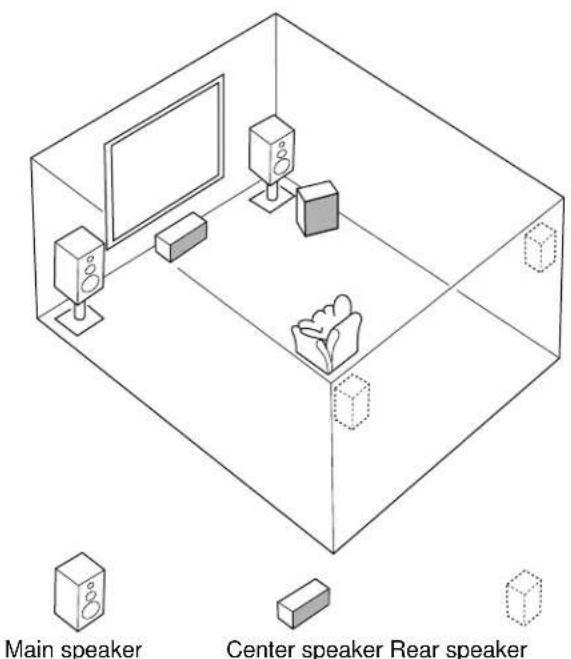

Subwoofer
Main: The position of your present stereo speaker system.
Rear: Behind your listening position, facing slightly inward. Nearly 1.8 m (approx. 6 feet) up from the floor.
Center: Precisely between the main speakers. (To avoid interference with TV sets, use a magnetically shielded speaker.)
Subwoofer: The position of the subwoofer is not so critical because low bass tones are not highly directional.
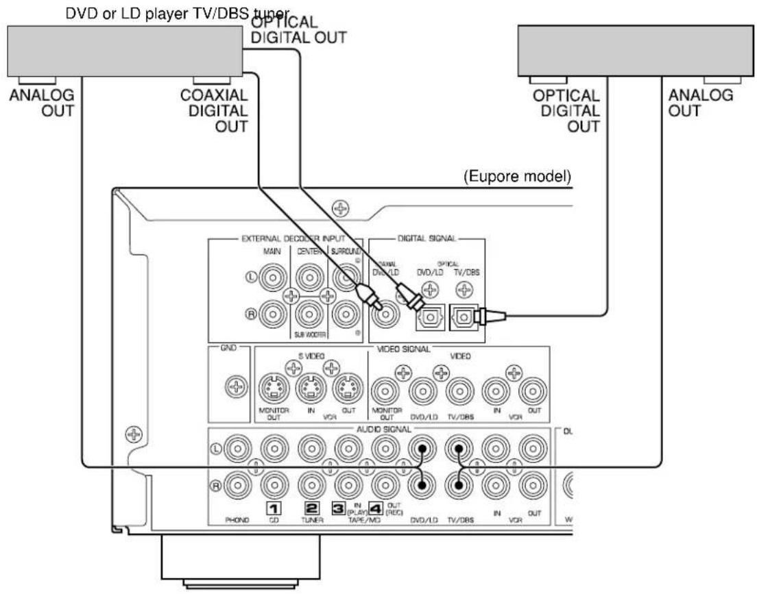
CONNECTIONS
Never plug in this unit and other components until all connections are completed.
CONNECTIONS WITH OTHER COMPONENTS
When making connections between this unit and other components, be sure all connections are made correctly, that is to say L (left) to L, R (right) to R, "+" to "+" and "-" to "-" Also, refer to the owner's manual for each component to be connected to this unit. * If you have YAMAHA components numbered as [1], [2], [3], [4], etc. on the rear panel, connections can be made easily by making sure to connect the output (or input) terminals of each component to the same-numbered terminals of this unit.
*See the next page.
*
SWITCHED AC OUTLET(S)
(China and General models) 3 SWITCHED OUTLETS (Europe models) 2 SWITCHED OUTLETS (U.K. model) 1 SWITCHED OUTLET
Use these to connect the power cords from your components to this unit.
The power to the SWITCHED outlets is controlled by this unit's STANDBY/ON or the provided remote control transmitter's POWER and STANDBY. These outlets will supply power to any component whenever this unit is turned on.
The maximum power (total power consumption of components) that can be connected to the SWITCHED AC OUTLET(S) is 100 watts.
*
GND terminal (Forturntable use)
Connecting the ground wire of the turntable to the GND terminal will normally minimize hum, but in some cases better results may be obtained with the ground wire disconnected.
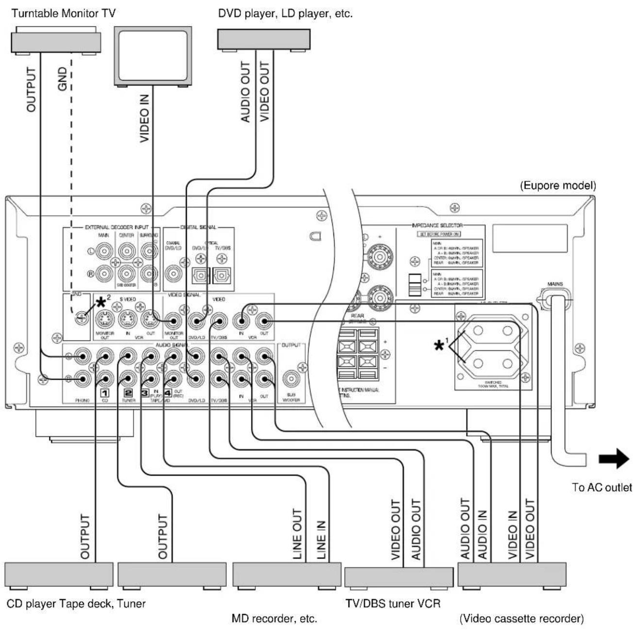
CONNECTING TO AN EXTERNAL DECODER
When using the DTS or other decoder with 6-channel discrete outputs, connect the 6CH DISCRETE OUTPUT terminals of the decoder to the EXTERNAL DECODER INPUT terminals of this unit.
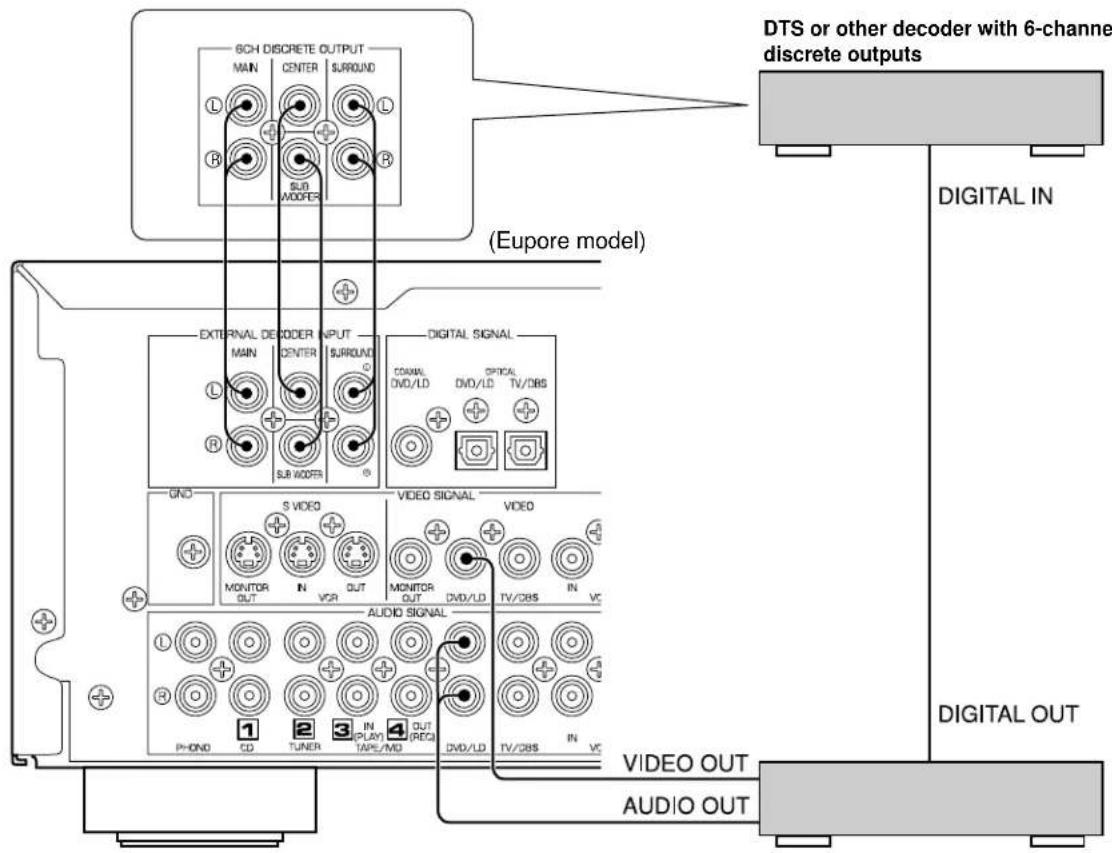
DVD player, LD player or other unit with digital outputs
CONNECTING TO DIGITAL (COAXIAL AND/OR OPTICAL) TERMINALS
If your DVD (LD) player, TV/DBS tuner, etc. are equipped with coaxial or optical digital audio signal output terminals, they can be connected to this unit's COAXIAL and/or OPTICAL digital signal input terminals.
To make a connection between optical digital audio signal terminals, remove the cover from each terminal, and then connect them by using a commercially available optical fiber cable that conforms to EIAJ standards. Other cables might not function correctly.
Even if you connect an audio/video unit to the COAXIAL (or OPTICAL) terminal of this unit, you must keep the unit connected with the same named analog audio signal terminals of this unit, because digital signal cannot be recorded by a tape deck or VCR connected to this unit. You can switch the selection of input signals between "digital" and "analog" easily. (See page 26 for details.)
Notes
- When connecting an audio/video unit to both of the digital and analog terminals of this unit, make sure to connect to both terminals of the same name.
- Be sure to attach the covers when the OPTICAL terminals are not being used, in order to protect the terminals from dust.
- The input signal from the DVD/LD input terminals is selected in the following order of priority. (input mode: AUTO position)
1 COAXIAL terminal
2 OPTICAL terminal
3 ANALOG terminal
- All digital audio signal input terminals are applicable to the sampling frequency of 32kHz , 44.1kHz and 48kHz .
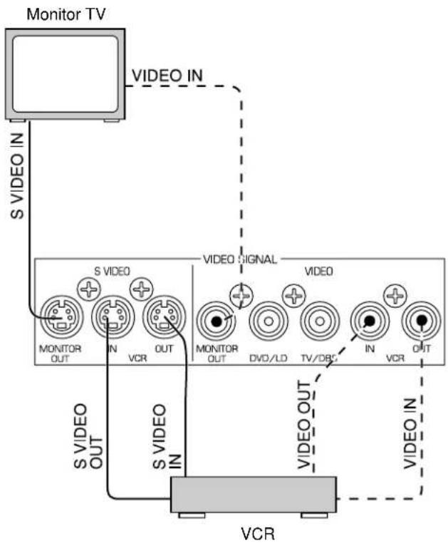
CONNECTING TO SVIDEO TERMINALS
If you have a VCR and a monitor equipped with "S" (high-resolution) video terminals, those terminals can be connected to this unit's SVIDEO terminals. Connect the VCR's "S" video input and output terminals to this unit's SVIDEO VCR OUT and IN terminals respectively, and connect the monitor's "S" video input terminal to this unit's SVIDEO MONITOR OUT terminal. Otherwise, connect the VCR's composite video terminals to this unit's composite VIDEO terminals, and connect the monitor's composite video input terminal to this unit's composite MONITOR OUT terminal.
Note
If video signals are sent to both SVIDEO input and composite input terminals, the signals will be sent to their respective output terminals.
CONNECTING TO VIDEO AUX TERMINALS (ON THE FRONT PANEL)
These terminals are used to connect any video input source, such as a camcorder, to this unit.
Note
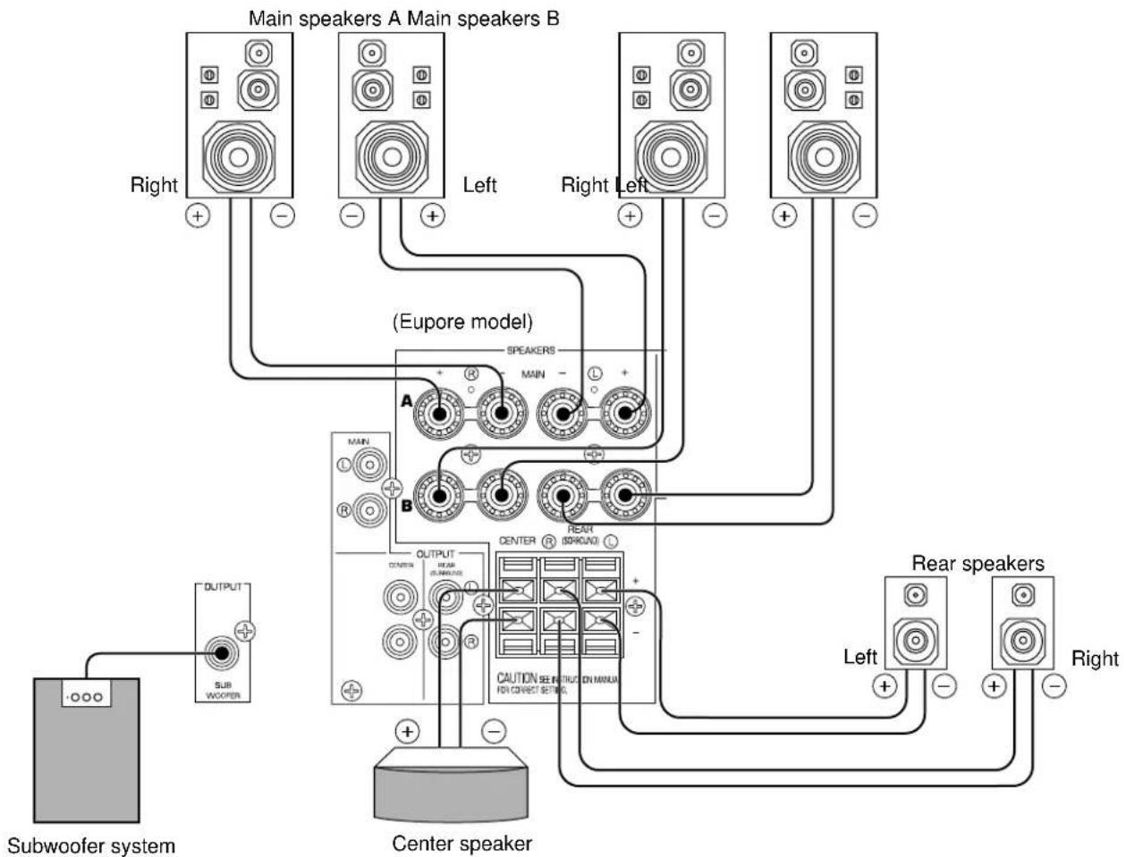
Use speakers with the specified impedance shown on the rear panel of this unit.
Note on main speaker connections:
One or two speaker systems can be connected to this unit. If you use only one speaker system, connect it to either the SPEAKERS A or B terminals.
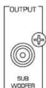
Note on a subwoofer connection:
You may wish to add a subwoofer to reinforce low frequencies or to output low bass sound from the subwoofer channel. If you have a subwoofer with built-in amplifier, including the YAMAHA Active Servo Processing Subwoofer System, connect the SUBWOOFER OUTPUT terminal of this unit to the input terminal of the subwoofer system. If you have an amplifier and a subwoofer, connect the SUBWOOFER OUTPUT terminal of this unit to the input terminal of the subwoofer amplifier, and then connect the speaker terminals of the subwoofer amplifier to the subwoofer.
Note on center speaker connection:
Center speaker can be connected to this unit. Place it on or under the TV.
How to connect
Connect the SPEAKERS terminals to your speakers with wire of the proper gauge, cut as short as possible. If the connections are faulty, no sound will be heard from the speakers. Make sure that the polarity of the speaker wires is correct, that is the + and - markings are observed. If these wires are reversed, the sound will be unnatural and lack bass.
Caution
Do not let the bare speaker wires touch each other and do not let them touch any metal part of this unit. This could damage this unit and/or speakers.
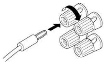
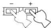
For connecting to the MAIN SPEAKERS terminals
Red: positive (+)
Black: negative (-)
① Unscrew the knob.
② Insert the bare wire. [Remove approx. 5 mm (1/4") insulation from the speaker wires.]
③ Tighten the knob and secure the wire.
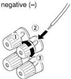
For connecting to the REAR and CENTER SPEAKERS terminals
Red: positive (+)
Black: negative (-)
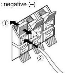
① Press the tab.
② Insert the bare wire. [Remove approx. 5 mm (1/4") insulation from the speaker wires.]
③ Release the tab and secure the wire.
Banana plug connections are also possible (except for U.K. and Europe models). Simply insert the banana plug connector into the corresponding terminal.
OUTPUT TERMINALS (FOR DRIVING SPEAKERS WITH EXTERNAL AMPLIFIERS)
(MAIN, CENTER and REAR OUTPUT terminals are provided for U.K. and Europe models only.)
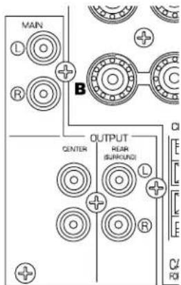
MAIN OUTPUT terminals
These terminals are for the main channel line output. There is no connection to these terminals when you use the built-in amplifier.
However, if you drive the main speakers with an external stereo power amplifier, connect the input terminals of the external amplifier (MAIN IN or AUX terminals of a power amplifier or an integrated amplifier) to these terminals.
- Output signals from the MAIN OUTPUT terminals are affected by the use of BASS, TREBLE, and BALANCE.
CENTER OUTPUT terminals
These terminals are for the center channel line output. There is no connection to these terminals when you use the built-in amplifier.
However, if you drive a center speaker with an external power amplifier, connect the input terminal of the external amplifier to this terminal.
If you are placing two center speakers on each side of the TV, use two amplifiers and connect each amplifier to one of the two CENTER OUTPUT terminals. Then connect the center speakers to the amplifiers.
REAR (SURROUND) OUTPUT terminals
These terminals are for the rear channel line output. There is no connection to these terminals when you use the built-in amplifier.
However, if you drive the rear speakers with an external stereo power amplifier, connect the input terminals of the external amplifier (MAIN IN or AUX terminals of a power amplifier or an integrated amplifier) to these terminals.
SUBWOOFER OUTPUT terminal
This terminal is for connecting to the input terminal of an amplifier for driving a subwoofer.
When the input signals to this unit are in normal 2-channel stereo, this terminal outputs only frequencies below 90Hz from the main and center channels. When discrete signals are input to this unit and are selected as the input source, this terminal outputs signals from the subwoofer channel.
Note
Output levels of signals from all of these terminals are adjusted by the use of VOLUME on the front panel or VOLUME ( ) on the remote control transmitter.
IMPEDANCE SELECTOR SWITCH
WARNING
Do not change the IMPEDANCE SELECTOR switch setting while the power of this unit is on, otherwise this unit may be damaged.
IF THIS UNIT FAILS TO TURN ON WHEN THE STANDBY/ON SWITCH IS PRESSED, the IMPEDANCE SELECTOR switch may not be fully set to either end. If so, set the switch to either end fully.
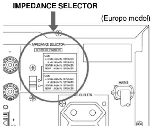
Select the position whose requirements your speaker system meets.

(Upper position)
Main: If you use one pair of main speakers, the impedance of each speaker must be 4 or higher. If you use two pairs of main speakers, the impedance of each speaker must be 8 or higher.
Center: The impedance of the speaker must be 6 or higher.
Rear: The impedance of each speaker must be 6 or higher.

(Lower position)
Main: If you use one pair of main speakers, the impedance of each speaker must be 8 or higher. If you use two pairs of main speakers, the impedance of each speaker must be 16 or higher.
Center: The impedance of the speaker must be 8 or higher.
Rear: The impedance of each speaker must be 8 or higher.
ADJUSTMENTS BEFORE USING THIS UNIT
SELECTING THE OUTPUT MODES
This unit provides you the following five functions to determine the method of distributing output signals to speakers suitable for your audio system. When speaker connections are all completed, select a proper position on each function to make the best use of your speaker system. (See "ADJUSTMENTS IN THE 'SET MENU' MODE" on page 35)
- CNTR (CENTER SPEAKER) 2. REAR (REAR SPEAKER) 3. MAIN (MAIN SPEAKER)
- BASS (LFE/BASS OUT) 5. M.LVL (MAIN LEVEL)
DESCRIPTION OF EACH FUNCTION
1. CNTR (CENTER SPEAKER)
Choices: LARGE/SMALL/NONE
Preset position: LARGE
LARGE: Select this position when your center speaker is approximately the same size as the main speakers.
SMALL: Select this position when you use a center speaker that is smaller than the main speakers. In this position, low bass signals (below 90Hz ) at the center channel are output from the main speakers (or the SUBWOOFER OUTPUT terminal if the SMALL position is selected on "3. MAIN" and the SW position is selected on "4. BASS").
NONE: Select this position when you do not have a center speaker. The center channel sound will be output from the left and right main speakers.
2. REAR (REAR SPEAKER)
Choices: LARGE/SMALL
Preset position: LARGE
LARGE: Select this position if your rear speakers have a high ability for bass reproduction, or a subwoofer is connected to the rear speaker in parallel. In this position, full range signals are output from the rear speakers.
SMALL: Select this position if your rear speakers do not have a high ability for bass reproduction. In this position, low bass signals (below 90Hz ) at the rear channels are output from the SUBWOOFER OUTPUT terminal (or the main speakers if the MAIN position is selected on "4. BASS").
3. MAIN (MAIN SPEAKER)
Choices: LARGE/SMALL
Preset position: LARGE
LARGE: Select this position if your main speakers have a high ability for bass reproduction. In this position, full range signals present at the main channels are output from the main speakers.
SMALL: Select this position if your main speakers do not have a high ability for bass reproduction. However, if your system does not include a subwoofer, do not select this position. In this position, low bass signals (below 90Hz ) at the main channels are output from the SUBWOOFER OUTPUT terminal if the SW or BOTH position is selected on "4. BASS".
4. BASS (LFE/BASS OUT)
Choices: SW/MAIN/BOTH
Preset position: SW
MAIN: Select this position if your system does not include a subwoofer. In this position, full range signals present at the main channels, signals from the LFE channel and other low bass signals that are selected on "1. CNTR" to "3. MAIN" to be distributed from other channels are output from the main speakers.
SW/BOTH:
Select either the SW or BOTH position if your system includes a subwoofer. In either position, signals at LFE channel and other low bass signals that are selected on "1. CNTR" to "3. MAIN" to be distributed from other channels are output from the SUBWOOFER OUTPUT terminal. When the LARGE position is selected on "3. MAIN", in the SW position, no signal is distributed from the main channels to the SUBWOOFER OUTPUT terminal, however in the BOTH position, low bass signals from the main channels are output to both of the main speakers and the SUBWOOFER OUTPUT terminal.
5. M.LVL (MAIN LEVEL)
Choices: NORMAL (NRML)/-10 dB
Preset position: NORMAL (NRML)
NORMAL (NRML):
Normally select this position.
-10 dB: Select this position if the sound output from the main speakers is too loud and cannot be balanced with the sound output from the center and rear speakers. In this position, the sound output from the main speakers is attenuated.
ADJUSTING METHOD
Operations should be made while watching the information on this unit's display.
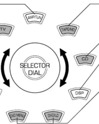
If you are using the remote control transmitter, set the SELECTOR DIAL to the AMP/TUN or DSP position on the remote control transmitter.


or
1 Turn the power on.
Front panel Remote control
or

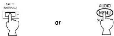
2 Press SET MENU once or more to select the title "1. CNTR" (so that "CNTR" appears on the display).
Front panel Remote control
or
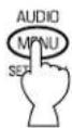
- After pressing SET MENU once on the remote control transmitter, you can also select the title by pressing . (Pressing goes back one selection.)
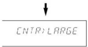
Appears.
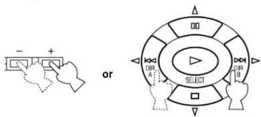
3 Press + or - once or more to select the position you want.
Front panel Remote control
Changes.
CNTR:SMALL
4 Repeat steps 2 and 3 to change selections on "2. REAR", "3. MAIN", "4. BASS" and/or "5. M.LVL" in the same way.
SPEAKER BALANCE ADJUSTMENT
This procedure lets you adjust the sound output level balance between the main, center and rear speakers using the built-in test tone generator. When this adjustment is performed, the sound output level heard at the listening position will be the same from each speaker. This is important for the best performance of the digital sound field processor, the Dolby Digital decoder and the Dolby Pro Logic Surround decoder.
The adjustment of each speaker output level should be done at your listening position with the remote control transmitter. After completing the adjustment of the output level for each speaker, use VOLUME ( ) on the remote control transmitter at your listening position to check if the adjustments are satisfactory.
Set the SELECTOR DIAL to the AMP/TUN or DSP position on the remote control transmitter.


or
1 Set VOLUME to the "∞" position.
Front panel
2 Turn the power on.
Front panel Remote control

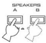
3 Select the main speakers to be used.
Front panel
- If you use two main speaker systems, press both A and B.
4
Set BASS, TREBLE and BALANCE to the "0" position.
Front panel
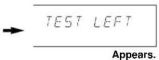
5
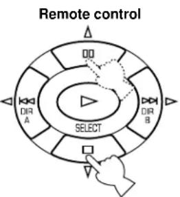
Press TEST (so that "TEST LEFT" appears on the display).

Remote control
6
Turn up the volume.
Remote control
You will hear a test tone (like pink noise) from the left main speaker, then the center speaker, then the right main speaker, then the right rear speaker, and then the left rear speaker, for about two seconds each. The display changes as shown below.
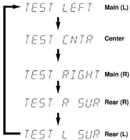
- If the function "1. CNTR" in the SET MENU mode is set to the NONE position, you will hear the center channel test tone from the left and right main speakers.
7
Adjust BALANCE so that the sound output level of the left main speaker and the right main speaker is the same.

Front panel
8 Adjust the sound output levels of the center speaker and the rear speakers so that they become almost as same as that of the main speakers.

Remote control
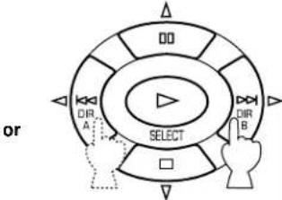
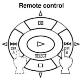
a) Press or once or more so that "CENTER", "R SUR." or "L SUR." appears on the display.
- Select "CENTER" to adjust the output level of the center speaker and select "R SUR." or "L SUR." to adjust the output level of the rear speakers.
b) Adjust the level.
- Pressing > raises and < lowers the level.
- While adjusting, the test tone is fixed on the selected speaker.
9 Press TEST once more to cancel the test tone.

Remote control

"TEST" disappears.
Notes
- Once you have completed these adjustments, you can adjust the overall sound level on your audio system by using VOLUME (or VOLUME ( ) on the remote control transmitter) only.
- If you use external power amplifiers, you may also use their volume controls to achieve the proper balance.
- If the function "1. CNTR" in the SET MENU mode is set to the NONE position, the sound output level of the center speaker cannot be adjusted in step 8. The center sound is automatically output from the left and right main speakers.
- If there is insufficient sound output from the center and rear speakers, you may decrease the main speaker output level by setting "5. M.LVL" to "-10 dB".
BASIC OPERATIONS
TO PLAY A SOURCE


Notes
- Set the SELECTOR DIAL to the AMP/TUN position on the remote control transmitter.
To operate the tuner, CD player, DVD/LD player, tape deck, MD recorder, or other components using this remote control transmitter, set the SELECTOR DIAL to the component to be used. (See "SETUP CODES" on page 42.)
1 Set VOLUME to the " 心 position.
2 Turn the power on.
Front panel Remote control
3 Select the desired input source by using INPUT. (For video sources, turn the TV/monitor ON.) See page 26 if you are using an external decoder or playing a tape or an MD.
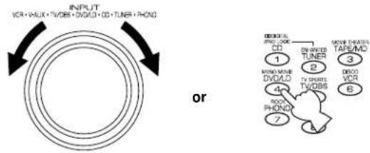
Front panel Remote control
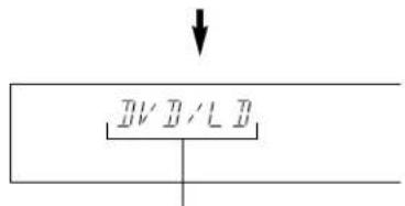
The name of the selected input source will appear on the display.
4 For the DVD/LD or TV/DBS source, the current input mode is also shown.
- To change the input mode for the DVD/LD or TV/DBS source, press INPUT MODE (or the button that you have pressed to select the input source in step 3 on the remote control transmitter) once or more until the desired input mode (AUTO or ANALOG) is shown on the display. (See page 26 for details on switching the input mode.)
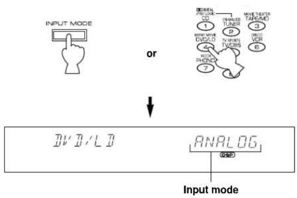
Front panel Remote control
5 Select the main speakers to be used.
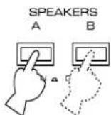
Front panel
- If you use two main speaker systems, press both A and B.
6 Play the source.
7 Adjust the volume to the desired output level.
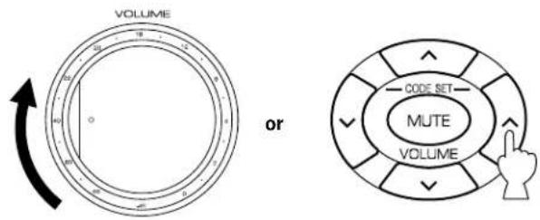
Front panel Remote control
8 If desired, adjust BASS, TREBLE, BALANCE, etc. (see below) and use the digital sound field processor. (see page 29.)
Selecting the SPEAKER system
Because one or two speaker systems (as main speakers) can be connected to this unit, SPEAKERS allow you to select speaker system A or B, or both at once.
Adjusting the BALANCE control
Adjust the balance of the output volume from the left and right speakers to compensate for sound imbalances caused by speaker location or listening room conditions.
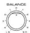
Note This control is effective only for the sound from the main speakers.
Adjusting the BASS and TREBLE controls
BASS: Turn this clockwise to increase (or counter-clockwise to decrease) the low frequency response.
TREBLE: Turn this clockwise to increase (or counter-clockwise to decrease) the high frequency response.
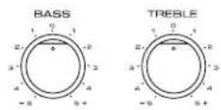
Note These controls are effective only for the sound from the main speakers.
To play a tape or an MD
Press TAPE/MD MON / EXT. DECODER so that the "TAPE/MD MON" indicator lights up on the display, then play the tape or MD.

Front panel Remote control
To stop playing the tape or MD, press TAPE/MD MON / EXT. DECODER twice so that the "TAPE/MD MON" indicator and "EXT. DECDR" disappear from the display and the play stops (or press TAPE/MD once on the remote control transmitter).
To use a decoder connected to the EXTERNAL DECODER INPUT terminals
Press TAPE/MD MON / EXT. DECODER once or more so that the "EXT. DECDR" appears on the display.
Start the play by operating the DTS or other external decoder, DVD player or LD player.

Front panel Remote control
To stop playing, press TAPE/MD MON / EXT. DECODER once so that "EXT. DECDR" disappears from the display and the play stops (or press EXT. DEC. on the remote control transmitter).
When you finish using this unit
Press STANDBY/ON on the front panel again or STANDBY on the remote control transmitter to turn this unit into the standby mode.
Notes on using INPUT
- By using INPUT, you can to select the program sources connected to the input terminals on the rear panel.
To play a video source connected to theVIDEO AUX terminals on the front panel, set INPUT to theVIDEO AUX position.
The audio source selected by INPUT will not be played if the "TAPE/MD MON" indicator lights up or if "EXT. DECDR" is displayed. -
If you select INPUT for a video source without canceling the selection of TAPE/MD MON / EXT. DECODER on the front panel (or, TAPE/MD or EXT. DEC. on the remote control transmitter), the playback result will be the video image from the video source and the sound from the input source selected by TAPE/MD MON / EXT. DECODER on the front panel (or, TAPE/MD or EXT. DEC. on the remote control transmitter).
-
Once you play a video source, its video image will not be interrupted even if INPUT for an audio source is selected.
- When you select an input source by using INPUT, the DSP program (or no DSP program) that was used when the same input source was selected the last time, will be automatically recalled.
Switching the input mode (for DVD/LD and TV/DBS)
This unit allows you to switch the input mode only for sources connected to the DVD/LD and TV/DBS input terminals (on the rear panel of this unit) that input two or three types of signals.
The following two input modes are provided.
AUTO: For the source connected to the DVD/LD input terminals:
This mode is automatically selected when you turn the power of this unit on. In this mode, input signal is automatically selected in the following order of priority.
- Digital input signal from the COAXIAL terminal
- Digital input signal from the OPTICAL terminal
- Analog input signal
For the source connected to the TV/DBS input terminals:
This mode is selected when you turn the power of this unit on if the AUTO position is selected on "10. INPUT" in the SET MENU mode. (For details, see page 36.) In this mode, input signal is automatically selected in the following order of priority.
- Digital input signal from the OPTICAL terminal
- Analog input signal
ANALOG:
In this mode, only analog input signal is selected even if a digital signal is input at the same time.
Select this mode when you want to use the analog input signal instead of the digital input signal.
Notes on input mode selection
- To playback a source with the Dolby Digital-decoded, set the input mode to AUTO.
- For the TV/DBS source only, the input mode selected on the function "10. INPUT" in the SET MENU mode is effective when you turn the power of this unit on.
- When you want to enjoy a source which has normal 2-channel signals with a Dolby Pro Logic Surround program, select the ANALOG mode.
- In the AUTO mode, there may be a case depending on some LD players or DVD players that when you make a search on a source encoded with the Dolby Digital during the play and then the play is restored, sound output is interrupted for a moment because the digital input signal is selected again.
1 Select the source to be recorded.
Front panel Remote control
2 Play the source and then turn VOLUME up to confirm the input source.
Front panel Remote control
3 Begin recording on the tape deck, MD recorder or VCR connected to this unit.
4 When the tape deck or MD recorder is used for recording, you can monitor the sounds being recorded by pressing TAPE/MD MON / EXT. DECODER so that the "TAPE/MD MON" indicator lights up on the display.

Front panel Remote control
Notes
- The settings of DSP and VOLUME, BASS, TREBLE and BALANCE have no effect on the material being recorded.
- Composite video and S video signals pass independently through this unit's video circuits. Therefore, when recording or dubbing video signals, if your video source unit is connected to provide only an S video (or only a composite video) signal, you can record only an S video (or only a composite video) signal on your VCR.
- A source that is connected to this unit through digital terminals only cannot be recorded by a tape deck or VCR connected to this unit.
- Please check the copyright laws in your country to record from records, compact discs, radio, etc. Recording of copyright material may infringe copyright laws.
If you watch a video software that uses scrambled or encoded signals to prevent it from being dubbed, there may be a case that the picture itself will be affected by those signals.
SETTING THE SLEEP TIMER
If you use the SLEEP timer of this unit, you can make this unit automatically switch to the standby mode. When you are going to sleep while enjoying a broadcast or other desired input source, this timer function is useful. The SLEEP timer can be controlled only with the remote control transmitter.
Notes
- To set the SLEEP timer for this unit, set the SELECTOR DIAL to a position other than the TV position. To set the SLEEP timer for your TV, set the SELECTOR DIAL to the TV position.
The components on which the SLEEP timer is effective are the sources connected to the SWITCHED AC OUTLET(S) on the rear panel of this unit.
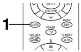
To set the SLEEP time
1 Press SLEEP once or more to select the desired SLEEP time.
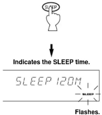
Remote control
Whenever SLEEP is pressed, the SLEEP time will change as follows.
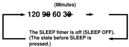
After a while, the "SLEEP" indicator lights up and the display returns to the indication before the SLEEP timer was set.
2 The unit will be switched to the standby mode automatically at the selected SLEEP time.
To cancel the selected SLEEP time

Remote control
Press SLEEP once or more so that "SLEEP OFF" appears on the display. (It will soon disappear and the "SLEEP" indicator will go off from the display.)
Note
The SLEEP timer setting can also be canceled by tuning this unit into the standby mode with STANDBY/ON on the front panel (or STANDBY on the remote control transmitter) or disconnecting the power plug of this unit from the AC outlet.
USING DIGITAL SOUND FIELD PROCESSOR(DSP)
This unit incorporates a sophisticated, multi-program digital sound field processor. The processor allows you to electronically expand and change the shape of the audio sound field from both audio and video sources, creating a theater-like experience in your listening room. You can create an excellent audio sound field by selecting a suitable sound field program (this will, of course, depend on what you are listening to), and adding any desired adjustments.
The following list gives you a brief description of the sound fields produced by each of the DSP programs. Keep in mind that most of these are precise digital recreations of actual acoustic environments. The data for these sound fields was recorded at actual locations using sophisticated sound field measurement equipment.
Note
The channel level balance between the left and right rear speakers may vary depending on the sound field you are listening to. This is due to the fact that most of these sound field are re-creation of actual acoustic environments.
BRIEF OVERVIEW OF DIGITAL SOUND FIELD PROGRAMS
| No. | PROGRAM | FEATURE |
| 1 | DOLBY PRO LOGIC ( DIT PRO LOGIC ) Functions when the input signal is analog or PCM audio, or encoded with the Dolby Digital in 2-channel. Speaker output: main, center, rear | Reproduces video discs, video tapes and similar sources which are Dolby Surround encoded and bear the "DOLBY SUR-ROUND" logo. |
| The built-in Dolby Pro Logic Surround decoder or Dolby Digital decoder precisely reproduces sounds and sound effects of a source encoded with Dolby Surround. The realization of a highly efficient decoding process improves crosstalk and channel separation and makes sound positioning smoother and more precise. | ||
| DOLBY DIGITAL ( DIGITAL ) Functions when the input signal is encoded with the Dolby Digital (not in 2-channel). Speaker output: main, center, rear | ||
| 2 | DOLBY PRO LOGIC ENHANCED ( DSP PRO LOGIC Functions when the input signal is analog or PCM audio, or encoded with the Dolby Digital in 2-channel. Speaker output: main, center, rear | Reproduces video discs, video tapes and similar sources which are Dolby Surround encoded and bear the "DOLBY SUR-ROUND" logo. |
| This program ideally simulates the multi-surround speaker systems of the 35 mm film theater. The Dolby Surround decoding and the digital sound field processing is precisely performed without altering the original sound orientation. The surround effects produced by this sound field folds around the viewer naturally from the rear to the left and right and toward the screen. | ||
| DOLBY DIGITAL ENHANCED ( DIGITAL DSP Functions when the input signal is encoded with the Dolby Digital (not in 2-channel). Speaker output: main, center, rear | ||
| Note: If the main channel sound is considerably altered by overadjustment of BASS or TREBLE, the relationship with the rear channels may produce an unnatural effect. | ||
| 3 | 70 mm MOVIE THEATER ( DSP PRO LOGIC Functions when the input signal is analog or PCM audio, or encoded with the Dolby Digital in 2-channel. Speaker output: main, center, rear | Ideal for reproducing video discs, video tapes and similar sources which are Dolby Surround encoded and bear the "DOLBY SURROUND" logo. |
| This program is ideal for precisely reproducing the sound design of the newest 70 mm/Dolby Digital multi-track films. The sound field is made to be similar to that of the newest movie theaters, so the reverberations of the sound field itself are restrained as much as possible. The three dimensional feeling of the sound field is emphasized, and dialog is precisely oriented on the screen. You can enjoy watching Sci-Fi, adventure movies, etc. with considerable presence. | ||
| DIGITAL MOVIE THEATER ( DIGITAL DSP Functions when the input signal is encoded with the Dolby Digital (not in 2-channel). Speaker output: main, center, rear | ||
| 4 | MONO MOVIE ( DSP) Functions when the input signal is analog or PCM audio, or encoded with the Dolby Digital in 2-channel. Speaker output: main, center, rear ( DIGITAL DSP) Functions when the input signal is encoded with the Dolby Digital (not in 2-channel). Speaker output: main, center, rear | This program is designed specifically to enhance mono source programs. Compared to a strictly mono setting, the sound image created in this mode is wider and slightly forward of the speaker pair, lending an immediacy to the overall sound. It is particularly effective when used with old mono movies, news broadcasting and dialog. |
| 5 | TV SPORTS ( DSP) Functions when the input signal is analog or PCM audio, or encoded with the Dolby Digital in 2-channel. Speaker output: main, center, rear ( DIGITAL DSP) Functions when the input signal is encoded with the Dolby Digital (not in 2-channel). Speaker output: main, center, rear | This program is furnished with a tight sound field in which the sound will not spread excessively on the front side, but the rear surround side produces a dynamic sound expansion. This program is the most suitable for sports programs. |
| 6 | DISCO ( DSP) Functions when the input signal is analog or PCM audio, or encoded with the Dolby Digital in 2-channel. Speaker output: main, rear ( DIGITAL DSP) Functions when the input signal is encoded with the Dolby Digital (not in 2-channel). Speaker output: main, center, rear | This program recreates the acoustic environment of a lively disco in the heart of a very lively city. The sound is dense and highly concentrated. It is also characterized by a high-energy, “immediate” sound. |
| 7 | ROCK CONCERT ( DSP) Functions when the input signal is analog or PCM audio, or encoded with the Dolby Digital in 2-channel. Speaker output: main, rear ( DIGITAL DSP) Functions when the input signal is encoded with the Dolby Digital (not in 2-channel). Speaker output: main, center, rear | This program is ideally suited for rock music. You will experience a very dynamic and lively sound field. |
| 8 | CONCERT HALL ( DSP) Functions when the input signal is analog or PCM audio, or encoded with the Dolby Digital in 2-channel. Speaker output: main, rear ( DIGITAL DSP) Functions when the input signal is encoded with the Dolby Digital (not in 2-channel). Speaker output: main, center, rear | In this program, the center will appear to be deep behind the main speakers, creating an expansive, large hall ambiance. Orchestra and opera music are suited to this sound field. |
Note: When the NONE position is selected on "1. CNTR" in the SET MENU mode, no sound is output from the center speaker(s).
PLAYING A SOURCE WITH THE DIGITAL SOUND FIELD PROCESSOR (DSP) EFFECT
1 Follow steps 1 to 7 shown in "BASIC OPERATIONS" on pages 24 to 25.
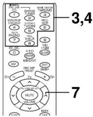
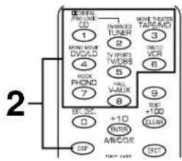
2 Select the desired DSP program that is suitable for the source.
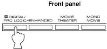
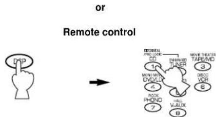
Press DSP. While the indicator lights up for about three seconds, select a DSP program using the numeric buttons (1 to 8).
- If the SELECTOR DIAL is set to the DSP position, you can also select a DSP program using the numeric buttons (1 to 8).
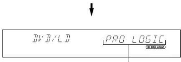
The name of selected program appears on the display.
3 If desired, adjust the delay time and the output level of each speaker. (For details, see pages 33 and 34.)
Notes
- You can select the program for each of the input sources. Once you select a program, it is linked with the input source selected at that time. So, when you select the input source next time, the same program is automatically called.
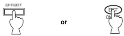
- If you prefer to cancel the DSP, press EFFECT or EFCT ON/OFF. The sound will be the normal 2-channel stereo without surround sound effect.
- When a monaural sound source is played with DOLBY PRO LOGIC or DOLBY PRO LOGIC ENHANCED, no sound is heard from the main speakers and the rear speakers. Sound is heard only from the center speaker. However, if the NONE position is selected on "1. CNTR" in the SET MENU mode, the main speakers output the sound of the center channel.
- If the main-source sound is considerably altered by overadjustment of BASS or TREBLE when this unit's Dolby Pro Logic Surround decoder or Dolby Digital decoder is used, the relationship between the center and rear channels may produce an unnatural effect.
This unit incorporates a Dolby Digital decoder and a Dolby Pro Logic Surround decoder for multi-channel sound reproduction of sources encoded with Dolby Surround. The operation of these decoders can be controlled by selecting a corresponding DSP program including the combined operation of YAMAHA DSP and Dolby Digital or Dolby Pro Logic Surround.
To enjoy a video source with the Dolby Pro Logic Surround or Dolby Digital decoded
When you select the program DOLBY PRO LOGIC/DOLBY DIGITAL, DOLBY PRO LOGIC ENHANCED/DOLBY DIGITAL ENHANCED or 70 mm MOVIE THEATER/DIGITAL MOVIE
THEATER, and the input signal of the source is 2-channel stereo, Dolby Pro Logic Surround is decoded. When some program is selected and the input signal of the source is encoded with Dolby Digital, Dolby Digital is automatically decoded.
- The following indicators on the display show you what sound processing is being made.
Lights up when the Dolby Digital is being decoded and the input signals of selected source encoded with Dolby Digital is not in 2-channel.

Lights up when the Dolby Pro Logic Surround is being decoded.
- In addition, for the program DOLBY PRO LOGIC/DOLBY DIGITAL, DOLBY PRO LOGIC ENHANCED/DOLBY DIGITAL ENHANCED or 70 mm MOVIE THEATER/DIGITAL MOVIE THEATER, the name of the program on the display will change according to the type of decoding. (For details, see page 29.)
Note
If the input signals of the source are encoded with Dolby Digital in 2-channel only, the sound processing for them is similar to that for analog or PCM audio signals.
To cancel the effect sound
EFFECT on the front panel and EFCT ON/OFF on the remote control transmitter make it simple to compare the normal stereo sound with the fully processed effect sound.
To cancel the effect sound and monitor only the main sound, press EFFECT or EFCT ON/OFF. Press EFFECT or EFCT ON/OFF once more to turn effect sound on.
Front panel Remote control
Notes
- If the effect sound is canceled when signals encoded with Dolby Digital are input to this unit, signals of all channels are mixed and are output from the main speakers.
- If EFFECT or EFCT ON/OFF is pressed to turn effect sounds off when the Dolby Digital is decoded, it may happen that the sound is output faintly or not output normally depending on the source. In that case, press EFFECT or EFCT ON/OFF to turn effect sounds on, or use input signals not encoded with Dolby Digital.
When using the digital sound field processor including the Dolby Pro Logic Surround decoder or the Dolby Digital decoder, you can adjust the delay time between the main sound and effect sound, and each speaker's output level as you prefer.
Adjusting method
If you are using the remote control transmitter, set the SELECTOR DIAL to the AMP/TUN or DSP position on the remote control transmitter.


or
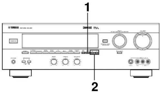
1 Press TIME/LEVEL once or more until the name of item which you want to adjust appears on the display.
Front panel Remote control
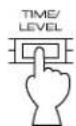

or
- After pressing TIME/LEVEL once on the remote control transmitter, you can also select the name of item by pressing .
When pressed, the selection changes as follows:
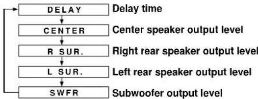
- Pressing on the remote control transmitter changes the selection in the reverse order.
- Depending on the mode of this unit, you cannot select all items.
2 Press + or - to adjust the settings for delay time or speaker output levels.
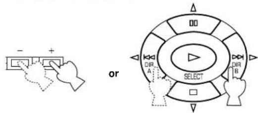
Front panel Remote control
3 Repeat steps 1 to 3 to adjust settings on any other item.
Adjusting delay time
You can adjust the time difference between the beginning of the sound from the main speakers and the beginning of the effect sound from the rear speakers.
The larger the value, the later the effect sound is generated.
This adjustment can be made to all programs individually.
Notes
- Adding too much delay will cause an unnatural effect with some sources.
- When + or - is pressed, the sound is momentarily interrupted.
| Program | Control range (ms) | Preset value |
| 1. DOLBY PRO LOGIC | 15 to 30 | 20 |
| DOLBY DIGITAL | 0 to 15 | 5 |
| 2. DOLBY PRO LOGIC ENHANCED | 15 to 30 | 20 |
| DOLBY DIGITAL ENHANCED | 0 to 15 | 5 |
| 3. 70 mm MOVIE THEATER | 15 to 30 | 20 |
| DIGITAL MOVIE THEATER | 1 to 99 | 16 |
| 4. MONO MOVIE | 1 to 99 | 49 |
| 5. TV SPORTS | 1 to 99 | 9 |
| 6. DISCO | 1 to 99 | 40 |
| 7. ROCK CONCERT | 1 to 99 | 16 |
| 8. CONCERT HALL | 1 to 99 | 44 |
Adjusting output level of the center, right rear and left rear speakers, and subwoofer
If desired, you can adjust the sound output level of each speaker even if the output level is already set in "SPEAKER BALANCE ADJUSTMENT" on pages 21 to 23.
Notes
-
Output level of the center speaker cannot be adjusted when the program DISCO, ROCK CONCERT or CONCERT HALL is selected, and the input signal is analog, PCM audio, or encoded with Dolby Digital in 2-channel.
-
If the function "1. CNTR" in the SET MENU mode is set to the NONE position, the sound output level of the center speaker cannot be adjusted. This is because, in this mode, the center sound is automatically output from the left and right main speakers.
- Once the output level is adjusted, the level will be the same for all digital sound field programs.
| Speakers | Control range (dB) | Preset value |
| CENTER | MIN, -20 to +10 | 0 |
| RIGHT SURROUND (Rear) | MIN, -20 to +10 | 0 |
| LEFT SURROUND (Rear) | MIN, -20 to +10 | 0 |
| SUBWOOFER | MIN, -20 to 0 | 0 |
Note
The values of the delay time, center/rear/subwoofer output level you set the last time will remain memorized even when this unit is in the standby mode. However, if the power cord is kept disconnected for more than one week, these values will automatically change back to the original factory settings.
ADJUSTMENTS IN THE “SET MENU” MODE
The following ten types of functions maximize the performance of your system and expand your enjoyment for audio listening and video watching.
- CNTR (CENTER SPEAKER)
- REAR (REAR SPEAKER)
- MAIN (MAIN SPEAKER)
- BASS (LFE/BASS OUT)
- M.LVL (MAIN LEVEL)
For details on "1. CNTR", "2. REAR", "3. MAIN", "4. BASS" and "5. M.LVL", see page 19. (Once you have selected the appropriate modes, you do not have to change settings unless any alteration is made in your speaker system.)
6. LFE [Adjusting the output level of the LFE (low frequency effect) channel]
Control range: -20 dB to 0 dB (in 1 dB step) Preset value: 0 dB
- This adjustment is effective only when the Dolby Digital is decoded and the signals of selected source encoded with the Dolby Digital contain LFE signals.
Adjusts the output level of the LFE (low frequency effect) channel. If the LFE signals are mixed with signals of other channels to output them from the same speakers, the ratio of LFE signal level to the level of other signals are adjusted. (See page 5 for details about the LFE channel.)
- LFE (LFE LEVEL)
- D.RNG (DYNAMIC RANGE)
- C DELAY (CENTER DELAY)
- GUARD (MEMORY GUARD)
- INPUT (INPUT MODE)
7. D.RNG (Adjusting dynamic range)
Choices: MAX/STD/MIN Preset position: MAX
- This adjustment is effective only when the Dolby Digital is decoded.
MAX: "Dynamic range" is the difference between the maximum level and the minimum level of sounds. Sounds on a movie originally designed for movie theaters feature very wide dynamic range. Dolby Digital technology can bring the original sound track into a home audio format with this wide dynamic range unchanged. In this position, a source encoded with the Dolby Digital is reproduced in the original sound track's wide dynamic range providing you with powerful sounds just like in a movie theater. Selecting this position will be even better if you can listen to a source in a high output level in a room specially soundproofed for audio/video enjoyment.
STD (Standard):
Powerful sounds of extremely wide dynamic range are not always suitable for home use. Depending upon the condition of your listening environment, it may not be possible to increase the sound output level as high as a movie theater. However, in a level suitable for listening to in your room, the low level parts of source sound often cannot be heard so well because they will be lost among noises in your environment. Dolby Digital technology also made it possible to reduce an original sound track's dynamic range for a home audio format by "compressing" the data of sound. In this position, a source encoded with the Dolby Digital is reproduced in the "compressed" dynamic range of the source suitable for low level listening.
MIN: In this position, dynamic range is more reduced than in the STD position. Selecting this position will be effective when you must listen to a source at lower level.
8. C DELAY [Adjusting the delay of center sounds (dialog etc.)]
Control range: 0 ms to 5 ms (in 1 ms step) Preset value: 0 ms
- This adjustment is effective only when the Dolby Digital is decoded and the signals of selected source encoded with the Dolby Digital contain center-channel signals.
Adjusts the delay between the main sounds (at the main channels) and dialog etc. (at the center channel).
The larger the value, the later the dialog etc. is generated.
This is for making sounds from the left main, center and right main speakers reach your listening position at the same time. This is achieved by delaying the sound from the center speaker if the distance from the center speaker to your listening position is shorter than the distance from the left or right main speaker to your listening position.
9. GUARD
Choices: ON/OFF Preset position: OFF
If you wish to prevent accidental alteration to SET MENU and other adjustments on this unit, select ON. The following functions on this unit can be locked by this operation.
- Functions in the SET MENU mode
- Functions in the TIME/LEVEL mode
- Functions when using TEST
10. INPUT (Selecting the initial input mode of the sources connected to the TV/DBS input terminals)
For the sources connected to the TV/DBS input terminals of this unit only, you can designate the input mode that is automatically selected when the power of this unit is switched on.
AUTO: In this position, the AUTO input mode is always selected when the power of this unit is switched on.
LAST: In this position, the input mode you selected last time is memorized and will not be changed even if the power of this unit is switched on.
- See page 26 for details on switching the input mode.
Adjusting method
Operations should be made while watching the information on this unit's display.
If you are using the remote control transmitter, set the SELECTOR DIAL to the AMP/TUN or DSP position on the remote control transmitter.

Press SET MENU once or more so that the title of function which you want to change appears on the display.
Front panel Remote control
- After pressing SET MENU once on the remote control transmitter, you can also select the title by pressing . (Pressing goes back one selection.)
Press + or - to select any desired position or edit parameters on the function.
Front panel Remote control
Repeat these steps to change and adjust settings on any other function.
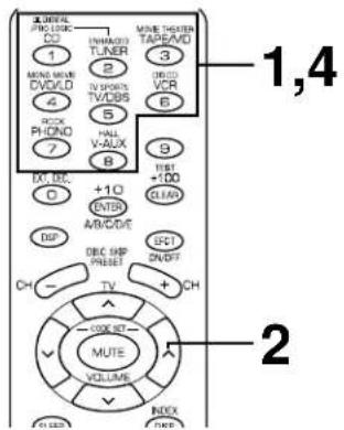
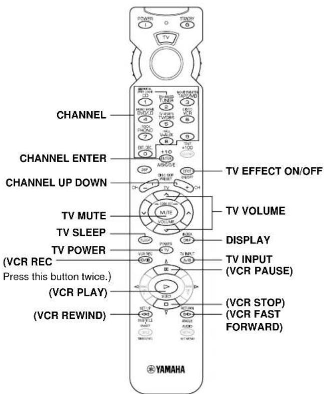
REMOTE CONTROL TRANSMITTER
You can use this remote control transmitter to control not only this unit but also other components connected to it. This is factory set to control this unit and most YAMAHA audio components. To control other brands of components, you must preset the remote control transmitter with the manufacturer's codes listed on pages 311 to 322.
Components which can be controlled
There are nine positions that you can select to control connected components with this remote control transmitter. When turning the SELECTOR DIAL, the position changes as follows:
AMP/TUN:
You can perform basic operations of this unit and control a YAMAHA tuner with the SELECTOR DIAL set to this position.
TV:
A television can be controlled.
CBL/DBS:
A cable television or DBS tuner can be controlled.
VCR:
A VCR can be controlled.
TAPE/MD:
The code for a YAMAHA tape deck is preset.
(Be sure to preset the proper code when operating a YAMAHA MD recorder.)
CD:
The code for a YAMAHA CD player is preset.
DSP:
This unit can be controlled and DSP programs can be selected directly.
DVD/LD & DVD MENU:
An LD player can be controlled using the DVD/LD position.
A DVD player can be controlled using the DVD/LD and DVD MENU position. When using the YAMAHA DVD player (DVD-1000 or DVD-S700), be sure to preset the code numb "4490".
Notes
- The shaded positions in the diagram above indicate that you can preset the code for the manufacturer of your component. Note that you can preset only one code for one position. For details, see "SETUP CODES" on page 42.
-
The DVD/LD and DVD MENU positions
-
Be sure that the SELECTOR DIAL is set to the DVD/LD position when presetting the code for a DVD or an LD player. The code that you preset to the DVD/LD position is also preset to the DVD MENU position simultaneously. You cannot preset the code for a DVD player when the SELECTOR DIAL is set to the DVD MENU position.
DVD MENU operations cannot be performed for some DVD players. -
When using a second (and third) VCR (For details, see "To use a second (and third) VCR" on page 42.)
If you are not using a CBL/DBS (cable TV or DBS tuner), the second (or third) VCR can be preset using the CBL/DBS position.
- If you are not using a DVD player, the second (or third) VCR can be preset using the DVD MENU position. Note that in this case you must preset a code for an LD player to the DVD/LD position even if an LD player is not used.
Basic Operations
1 Select the component that you want to control by turning the SELECTOR DIAL. Note: Turn the SELECTOR DIAL until it stops with a click.
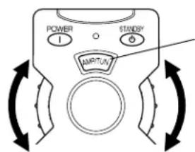
The component name is displayed in this window.
2 Press the desired operation button.
Note: Press the button with the remote control transmitter aimed at the front panel.
Indicator
The indicator will flash when the button is pressed.
Faintly colored buttons do not function.
Note: TV POWER and TV VOLUME function if you have preset the code for your TV.

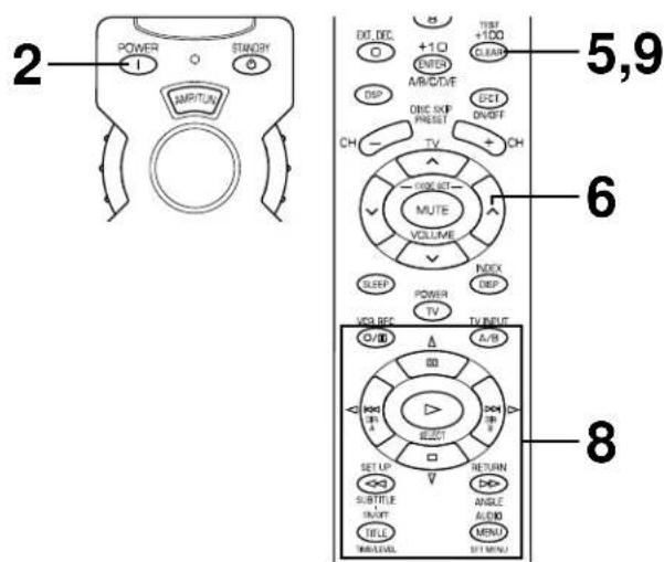
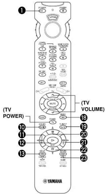
AMP/TUN
DSP

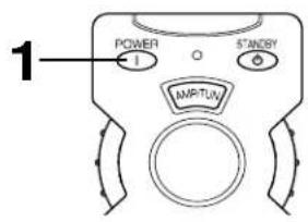
POWER
This button turns this unit on.

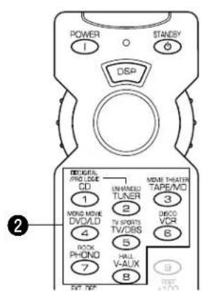
INPUT
Press these buttons to select the program source.

EXT. DEC.
Press this button when using a external decoder.

A/B/C/D/E
Press this button to select a group of preset stations when using the YAMAHA tuner.

DSP selector
Press this button. While the indicator lights up for about three seconds, select a DSP program using the number buttons (1 to 8). No DSP program can be selected after the indicator goes off.

PRESET (+ / - )
Press these buttons to select the preset station number when using the YAMAHA tuner.

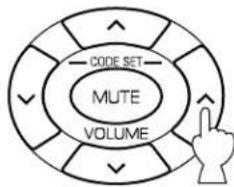
VOLUME
Press these buttons to adjust the volume level.

MUTE
Press this button to mute the sound. To cancel mute, press this button once more, or press the operation buttons of this unit.

SLEEP
Press this button to set the SLEEP timer.

(LEFT)
This button is used to adjust the settings of the SET MENU mode and the TIME/LEVEL mode.

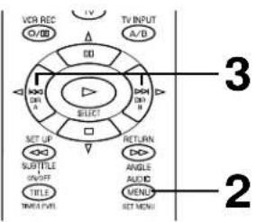
TIME/LEVEL
Press this button to select the item in the TIME/LEVEL mode.

STANDBY
Press this button to turn this unit into Standby mode.

TEST
Press this button to output a test tone for adjusting the output level of the speakers.

EFCT (EFFECT) ON/OFF
Press this button to switch the DSP program on or off.

(BACK)
Press this button to go back one selection in the SET MENU mode and TIME/LEVEL mode.

(RIGHT)
This button is used to adjust the settings of the SET MENU mode and the TIME/LEVEL mode.

(NEXT)
Press this button to advance one selection in the SET MENU mode and TIME/LEVEL mode.

SET MENU
Press this button to select functions in the SET MENU mode.

DSP program
Press these buttons to select the DSP program (1 to 8). When you select the input source, set the SELECTOR DIAL to the AMP/TUN position.
Note: The function of all buttons other than DSP program is the same as with the AMP/TUN position.
Faintly colored buttons do not function. For the buttons which are not described here, see "AMP/TUN" on page 38. For details, please refer to the owner's manual for each component.
TAPE/MD
Notes: - TV POWER and TV VOLUME function if you have preset the code for your TV. - Be sure to preset the proper code for your MD recorder.
TAPE
1 POWER
This button turns this unit on under the default settings. (The code for a YAMAHA tape deck is preset as the default code.) If other codes are preset, only those preset tape decks having a remote controller with a POWER button will be turned on.
10 o(REC/PAUSE)
Press this button to pause recording on a tape deck.
1DIRA
Press this button to select the playing direction of deck A.
12 PLAY
Press this button to play a tape.
13←REWIND)
Press this button to rewind a tape.
19 DECK A/B
Press this button to select double cassette tape deck A or B.
2DIRB
Press this button to select the playing direction of deck B.
22□(STOP)
Press this button to stop operation of a tape.
FAST FORWARD)
Press this button to fast forward a tape.
MD
1 POWER
This button turns this unit on if you have preset the code for the YAMAHA MD recorder. If other codes are preset, only those MD recorders having a remote controller with a POWER button will be turned on.
10 o(REC/PAUSE)
1 (SKIP)
12 PLAY
13 (BACKWARD)
18 DISPLAY
20 (PAUSE)
21 (SKIP)
22□(STOP)
FAST FORWARD)
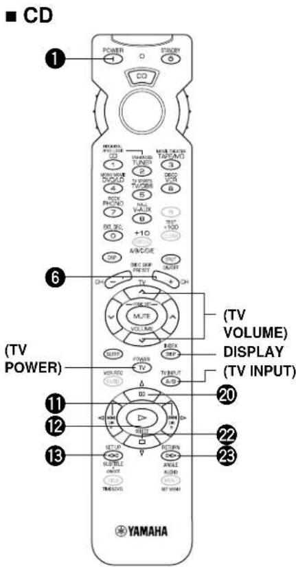
Note: TV POWER, TV VOLUME and TV INPUT function if you have preset the code for your TV.
1 POWER
This button turns this unit on under the default settings. (The code for a YAMAHA CD player is preset as the default code.) If other codes are preset, only those CD players having a remote controller with a POWER button will be turned on.
DISCSKIP (+ / - )
Press this button to skip to the next or previous CD.
1 (SKIP)
Press to skip to the next track. Press to skip to the previous track.
12D(PLAY)
Press this button to play a CD.
13 (BACKWARD)
Press this button to backward the track that is playing.
20 uu(PAUSE)
Press this button to pause operation. This button functions as PAUSE/STOP for operating YAMAHA CD players under default settings.
22 (STOP)
Press this button to stop operation. This button functions as PAUSE/STOP for operating YAMAHA CD players under default settings.
FAST FORWARD)
Press this button to fast forward the track that is playing.
Faintly colored buttons do not function. For the buttons which are not described here, see "AMP/TUN" on page 38. For details, please refer to the owner's manual for each component.
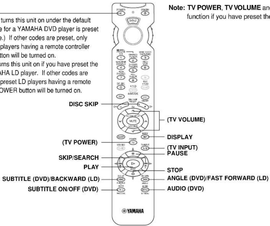
DVD/LD
POWER
(DVD) This button turns this unit on under the default settings. (The code for a YAMAHA DVD player is preset as the default code.) If other codes are preset, only those preset DVD players having a remote controller with a POWER button will be turned on.
(LD) This button turns this unit on if you have preset the code for the YAMAHA LD player. If other codes are preset, only those preset LD players having a remote controller with a POWER button will be turned on.
Note: TV POWER, TV VOLUME and TV INPUT
function if you have preset the code for your TV.
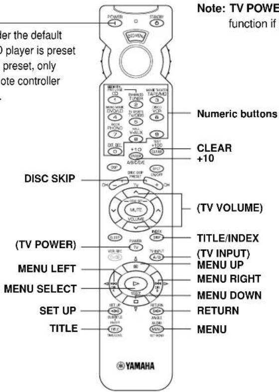
DVD MENU
POWER
(DVD) This button turns this unit on under the default settings. (The code for a YAMAHA DVD player is preset as the default code.) If other codes are preset, only those preset DVD players having a remote controller with a POWER button will be turned on.
Note: TV POWER, TV VOLUME and TV INPUT
function if you have preset the code for your TV.
Faintly colored buttons do not function. For the buttons which are not described here, see "AMP/TUN" on page 38. For details, please refer to the owner's manual for each component.
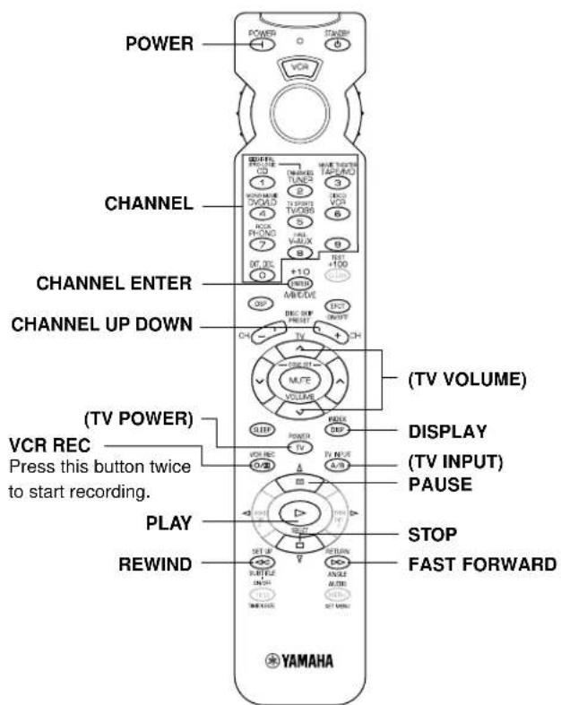
VCR
Note: TV POWER, TV VOLUME and TV INPUT function if you have preset the code for your TV.
TV
Note: You can control your VCR if you have preset the code for it.
CBL/DBS
Note: TV POWER, TV VOLUME and TV INPUT function if you have preset the code for your TV.
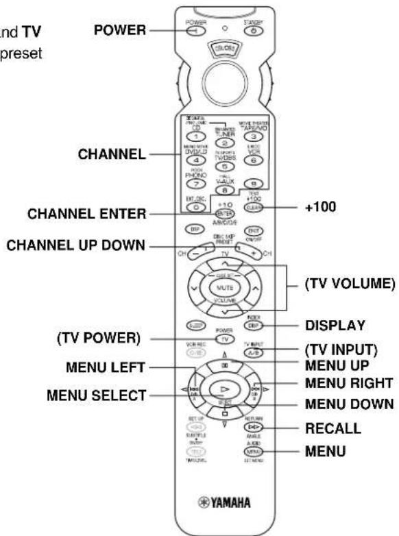
SETUP CODES
Preseting the remote control transmitter
Perform the presetting procedure for each component you want to control with this remote control transmitter.
Note: If your component does not respond to any of the codes listed for the manufacturer, use the original remote control that came with the component.
To control your components (MD recorder, DVD player, TV etc.)
- Turn on the component to be used.
- Set the SELECTOR DIAL to the desired component (TAPE/MD, DVD/LD, TV etc.).
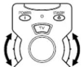
- Press both VOLUME buttons ( ) at the same time until the indicator flashes twice.
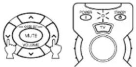
- Use the numeric buttons to enter the four-digit manufacturer's code for the component to be used. Make sure that the indicator flashes twice. If the indicator does not flash, repeat step 3 and re-enter the code.
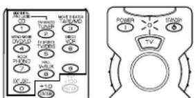
- Press POWER (or any other button) on the remote control transmitter to check if you have preset the code correctly. If the component cannot be controlled using the remote control transmitter, try entering another code for the same manufacturer.
To use a second (and third) VCR
You can use the CBL/DBS and/or DVD MENU positions to control a second VCR (and/or third) if a CBL (or DBS) or DVD player is not used.
If you are using the DVD MENU position for a second (or third) VCR, you must preset a code for an LD player to the DVD/LD position.
- Turn on the VCR to be used.
- Set the SELECTOR DIAL to the CBL/DBS or DVD MENU position.
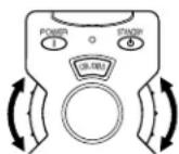
- Press both VOLUME buttons ( ) at the same time until the indicator flashes twice.
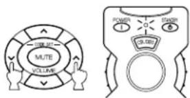
- Press MUTE.
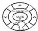
- Use the numeric buttons to enter the four-digit code for a second (or third) VCR. Make sure that the indicator flashes twice. If the indicator does not flash, repeat step 3 and 4, and re-enter the code.
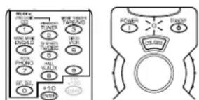
- Press POWER (or any other button) on the remote control transmitter to check if you have preset the code correctly. If the VCR cannot be controlled using the remote control transmitter, try entering another code for the same manufacturer.
Returning to the default code
To return all components to the default code, follow these steps.
- Press both VOLUME buttons ( ) at the same time until the indicator flashes twice.
- Enter the code number "9987".
- Make sure that the indicator flashes twice.
To return each component to the default code, follow these steps.
- Set the SELECTOR DIAL to the component to be return to the default code.
- Press both VOLUME buttons ( ) at the same time until the indicator flashes twice.
- Enter the code number "9999".
- Make sure that the indicator flashes twice.
The following codes are preset as the default code.
Default codes
| POSITION | Component Code | 1 | Code2 |
| TV TV 003 | 7 0047 | ||
| CBL/DBS | DBS tuner 24 | 55 2566 | |
| VCR VCR | 3072 3060 | ||
| DVD/LD D | VD player | 4545 YAMAHA | |
| CD CD player | 6187 YAMAHA | ||
| TAPE/MD | Tape deck | 8524 YAMAHA | |
1: U.K. and Europe models
2: China and General models
We recommend that you write all code numbers you have preset on the "Quick Reference Card".
NOTES ABOUT THE REMOTE CONTROL TRANSMITTER
Battery installation
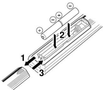
Battery replacement
If the remote control transmitter operates only when it is closed to this unit, the batteries are weak. Replace both batteries with new ones.
Be sure to replace batteries within about two minutes. If it takes longer than two minutes, the codes preset for the remote control transmitter will return to the default codes.
Notes
- Use only AA, R6, UM-3 batteries for replacement.
- Be sure the polarities are correct. (See the illustration inside the battery compartment.)
- Remove the batteries if the remote control transmitter will not be used for an extended period of time.
- If batteries leak, dispose of them immediately. Avoid touching the leaked material or letting it come in contact with clothing, etc. Clean the battery compartment thoroughly before installing new batteries.
Remote control transmitter operation range
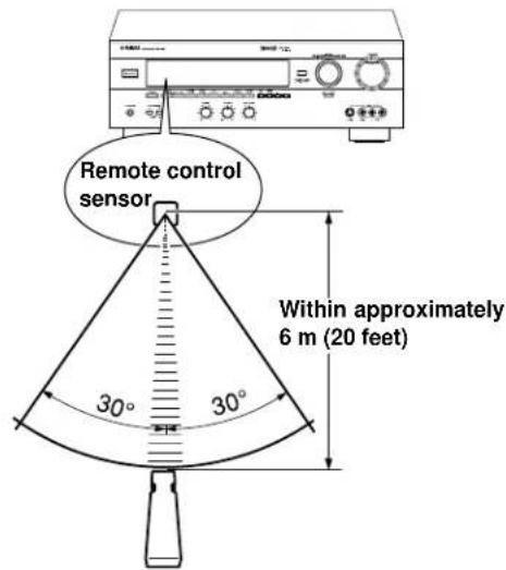
Notes
- There should be no large obstacles between the remote control transmitter and this unit.
- If the remote control sensor is directly illuminated by strong lighting (especially an inverter type of fluorescent lamp etc.), it might cause the remote control transmitter not to work correctly. In this case, reposition this unit to avoid direct lighting.
TROUBLESHOOTING
If the unit fails to operate normally, check the following points to determine whether the fault can be corrected by the simple measures suggested. If it cannot be corrected, or if the fault is not listed in the SYMPTOM column, disconnect the power cord and contact your authorized YAMAHA dealer or service center for help.
| SYMPTOM | CAUSE | REMEDY | |
| Amplifier | The unit fails to turn on when STANDBY/ON is pressed, or turns into the standby mode suddenly soon after the power is turned on. | Power cord is not plugged in or is not completely inserted. | Firmly plug in the power cord. |
| The IMPEDANCE SELECTOR switch on the rear panel is not fully set to the upper or lower end. | Set the switch fully to the upper or lower end. | ||
| The unit does not work normally. | There is an influence of strong external noise (lightning, excessive static electricity, etc.) or a misoperation while using this unit. | Turn this unit into the standby mode and disconnect the AC power cord from the AC outlet. After about 30 seconds have passed, connect the power and operate this unit again. | |
| No sound or no picture. | Incorrect output cord connections. | Connect the cords properly. If the problem persists, the cords may be defective. | |
| Appropriate input source is not selected. | Select an appropriate input source with INPUT. | ||
| SPEAKERS are not set properly. | Set SPEAKERS corresponding to the speakers in use to the ON position. | ||
| Speaker connections are not secure. | Secure the connections. | ||
| No picture. | There is no S video terminal connection between this unit and the TV, though S video signals are input to this unit. | Connect this unit's SVIDEO MONITOR OUT terminal to the TV's S video input terminal. | |
| The sound suddenly goes off. | The protection circuit has been activated because of short circuit etc. | Turning the unit into the standby mode and then on again will reset the protection circuit. | |
| The SLEEP timer has functioned. | Cancel the SLEEP timer function. | ||
| Only one side speaker outputs sound. | Incorrect setting of BALANCE. | Adjust it to the appropriate position. | |
| Incorrect cord connections. | Connect the cords properly. If the problem persists, the cords may be defective. | ||
| A "humming" sound can be heard. | Incorrect cord connections. | Firmly connect the audio plugs. If the problem persists, the cords may be defective. | |
| No connection from the turntable to the GND terminal. | Make the GND connection between the turntable and this unit. | ||
| The volume level is low while playing a record. | The record is being played on a turntable with an MC cartridge. | The turntable should be connected to the unit through the MC head amplifier. | |
| The volume level cannot be increased, or the sound is distorted. | The component connected to the REC OUT terminals of this unit is in the standby mode. | Turn the power to the component on. | |
| No sound from the rear speakers. | The sound output level of the rear speakers is set to minimum. | Raise the sound output level of the rear speakers. | |
| A monaural sound source is being played in DOLBY PRO LOGIC or DOLBY PRO LOGIC ENHANCED mode. | Select another sound field program suitable for the monaural sound source. | ||
| No sound from the center speaker. | The sound output level of the center speaker is set to minimum. | Raise the sound output level of the center speaker. | |
| The center channel mode is in NONE mode. | Select LARGE or SMALL. | ||
| Incorrect sound field program selection. | Select the appropriate program. | ||
| Remote control transmitter | The remote control transmitter does not work. | Direct sunlight or lighting (of an inverter type of fluorescent lamp etc.) is striking the remote control sensor of the main unit. | Change the position of the main unit. |
| The manufacturer's code is not set properly. | Set the code again. | ||
| The proper manufacturer's code for the component to be controlled is not set. | Try entering another code for the same manufacturer. | ||
| The component to be controlled is not selected. | Set the SELECTOR DIAL to the proper position. | ||
| Others | The sound is degraded when listening with headphones to a CD player or tape deck that is connected to this unit. | This unit is in the standby mode. | Turn the power of the unit on. |
SPECIFICATIONS
AUDIO SECTION
Minimum RMS Output Power
MAIN L/R
8 ohms, 20 Hz to 20 kHz, 0.04% THD 65 W + 65 W
CENTER
8 ohms, 20 Hz to 20 kHz, 0.04% THD 65 W
REAR L/R
8 ohms, 20 Hz to 20 kHz, 0.04% THD 65 W + 65 W
Maximum Power
[China and General models only]
MAIN L/B
8 ohms, 1 kHz, 10% THD 105 W + 105 W
CENTER
8 ohms, 1 kHz, 10% THD 105 W
BEAR L/R
8 ohms, 1 kHz, 10% THD 105 W + 105 W
Dynamic Power per Channel
(by IHF Dynamic Headroom measuring method)
8/6/4/2 ohms 90/110/135/160 W
DIN Standard Output Power per Channel [Europe model only]
4 ohms, 1 kHz, 0.7% THD 110 W
IEC Power
[Europe model only]
8 ohms, 1 kHz, 0.04% THD .... 75 W + 75 W
Power Band Width
8 ohms, 35 W, 0.1% THD
10 Hz to 50 kHz
Damping Factor (SPEAKERS A)
8 ohms, 20 Hz to 20 kHz 60 or more
Input Sensitivity/Impedance
PHONO MM 2.5 mV/47 k-ohms CD/TAPE-MD/DVD-LD/TV-DBS/VCR/
VIDEO AUX 150 mV/47 k-ohms
EXT. DECODER
MAIN L/R 150 mV/47 k-ohms
CENTER/SURROUND L/R/SUBWOOFER 150 mV/40 k-ohms
Maximum Input Signal
PHONO MM
1 kHz, 0.1% THD 100 mV or more
CD/TAPE-MD/DVD-LD/TV-DBS/VCR/
VIDEO AUX (EFFECT ON)
1 kHz, 0.5% THD 2.2 V or more
Output Level/Impedance
REC OUT 150 mV/1.2 k-ohms
PRE OUT
[U.K.and Europe models only] 2.1 V/1.2 k-ohms
SUBWOOFER
(MAIN SP: SMALL) 4.0 V/1.2 k-ohms
Headphones Jack Rated Output/Impedance CD/TAPE-MD/DVD-LD/TV-DBS/VCR/VIDEO AUX input,
1 kHz, 150 mV, 8 ohms ....... 0.5 V/390 ohms
Frequency Response (20 Hz to 20 kHz)
CD/TAPE-MD/DVD-LD/TV-DBS/VCR/
VIDEO AUX to MAIN L/R SP OUT
0±0.5dB
RIAA Equalization Deviation
PHONO MM 0±0.5 dB
Total Harmonic Distortion (20 Hz to 20 kHz)
PHONO MM to REC OUT
1 V.0.02% or less CD/TAPE-MD/DVD-LD/TV-DBS/VCR/
VIDEO AUX to MAIN L/R SP OUT
EFFECT OFF)
8 ohms, 35 W .0.025% or less
Signal-to-Noise Ratio (IHF-A Network)
PHONO MM to REC OUT
(5 mV, Input Shorted)
[U.K. and Europe models]
81 dB or more
[China and General models]
86 dB or more CD/TAPE-MD/DVD-LD/TV-DBS/VCR/
VIDEO AUX to SP OUT (EFFECT OFF)
(150 mV, Input Shorted) ....96 dB or more
Residual Noise (IHF-A Network)
MAIN L/R SP OUT. 150 V or less
Channel Separation
(Vol. -30 dB, EFFECT OFF)
PHONO MM
(Input Shorted, 1 kHz/10 kHz)
60 dB or more/55 dB or more
CD/TAPE-MD/DVD-LD/TV-DBS/VCR/
VIDEO AUX
(Input 5.1 k-ohms Terminated, 1 kHz/10 kHz)
60 dB or more/45 dB or more
Tone Control Characteristics
BASS:Boost/cut ± 10 dB (50 Hz)
Turnover Frequency. 350 Hz
TREBLE: Boost/cut. ±10 dB (20 kHz)
Turnover Frequency. 3.5 kHz
Filter Characteristics
MAIN L/R, REAR L/R (SPEAKER: SMALL)
(H.P.F) fc = 90 Hz,12 dB/oct .
SUBWOOFER
(L.P.F) .90 Hz, 18 dB/oct.
VIDEO SECTION
Video Signal Type
[U.K. and Europe models] PAL
[China and General models] ...NTSC/PAL
Video Signal Level 1 Vp-p/75 ohms
S-Video Signal Level
Y 1 Vp-p/75 ohms
C 0.286 Vp-p/75 ohms
Maximum Input Level 1.5 Vp-p or more
Signal-to-Noise Ratio 50 dB or more
Monitor Out Frequency Response
5 Hz to 10 MHz, -3 dB
GENERAL
Power Supply
[U.K. and Europe models]
AC230V,50Hz
[China model] AC 220 V, 50 Hz
[General model]
AC 110/120/220/240 V, 50/60 Hz
Power Consumption
[U.K. and Europe models] 300 W
[China and General models] 310 W
Maximum Power Consumption
[General model only]
5-ch, 10% THD 650W
AC Outlets
3 SWITCHED OUTLETS
[China and General models]
100 W max. total
2 SWITCHED OUTLETS
[Europe model] 100 W max. total
SWITCHED OUTLET
[U.K. model] 100 W max. total
Dimensions (W× H× D)
435x151x391mm
(17 - 1 / 8^ × 5 - 15 / 16^ × 15 - 3 / 8^ )
Weight 12.5 kg (27 lbs. 8 oz.)
Accessories . Remote control transmitter
Batteries
Specifications are subject to change without notice.
CHARACTERISTIQUES
ACCESSIONS FOURNIS 2
CHARACTERISTIQUES. 47
ATTENTION 48
- Introduction
CHARACTERISTIQUES DE L'EFFET SONORE 49
LES COMMANDES ET LEURS FONCTIONS 51
- Préparatifs
INSTALLATION DES ENCEINTES ACOUSTIQUES...54
RACCORDEMENTS 56
REGLAGLES AVANT D'UTILISER CET APPAREIL .... 63
Borne SUBWOOFER OUTPUT
REPRODUCTION D'UNE SOURCE
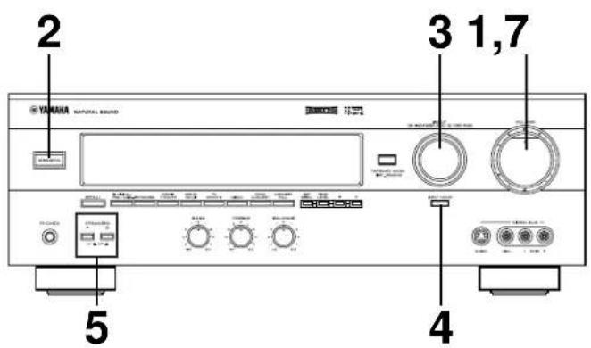
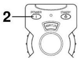
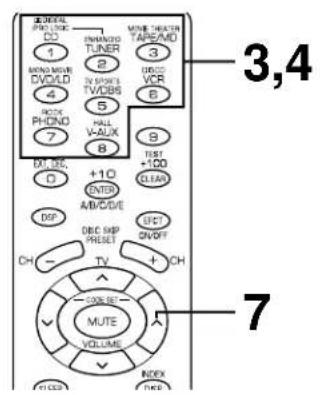
Remarques
8/6/4/2 ohms 90/110/135/160 W
PHONO MM 2.5 mV/47 kilohms CD/TAPE-MD/DVD-LD/TV-DBS/VCR/
VIDEO AUX 150 mV/47 kilohms EXT. DECODER
MAIN L/R 150 mV/47 kilohms
CENTER/SURROUND L/R/SUBWOOFER 150 mV/40 kilohms
1 kHz, 150 mV, 8 ohms
0.5 V/390 ohms
CD/TAPE-MD/DVD-LD/TV-DBS/VCR/VIDEO AUX a MAIN L/R SP OUT (EFFECT OFF)
CD/TAPE-MD/DVD-LD/TV-DBS/VCR/
CD/TAPE-MD/DVD-LD/TV-DBS/VCR/
VIDEO AUX
(Entree 5,1 kilohms refermee, 1 kHz/10 kHz) 60 dB ou plus/45 dB ou plus
Haupt: 65 W + 65 W (8Ω) RMS
Ausgangsleistung,


