
RXV630RDS - Home cinema amp YAMAHA - Free user manual and instructions
Find the device manual for free RXV630RDS YAMAHA in PDF.

| Product Type | Home Theater Amplifier |
| Brand | YAMAHA |
| Model | RXV630RDS |
| Dimensions (W × H × D) | 435 × 161 × 390 mm |
| Weight | 11.5 kg |
| Power Supply | 110-240 V AC, 50/60 Hz (depending on model) |
| Power Consumption | 290 W (standby: 0.6 W) |
| Output Power | 6 × 75 W (8 Ω, 20 Hz - 20 kHz, 0.06% THD) |
| Built-in Decoders | Dolby Digital, Dolby Digital EX, DTS, DTS-ES, Dolby Pro Logic II |
| DSP Processor | CINEMA DSP, Virtual CINEMA DSP, SILENT CINEMA DSP |
| Tuner | AM/FM with RDS, 40 presets |
| Audio Inputs | 6 digital (optical/coaxial), 6 analog (including 6CH), phono |
| Video Inputs | Composite, S-Video, Component (3 inputs) |
| Speaker Outputs | Terminals A/B for front, center, rear, rear center, subwoofer |
| Line Outputs | Pre-out for all channels, headphone output |
| Included Accessories | Remote control, batteries, AM loop antenna, indoor FM antenna |
| Maintenance | Clean with a dry, clean cloth; do not use solvents |
| Repairability | Do not open the casing; contact an authorized YAMAHA service center |
| Warranty | Refer to the warranty provided with the device |
| Operating Temperature | 5 °C to 35 °C |
Frequently Asked Questions - RXV630RDS YAMAHA
User questions about RXV630RDS YAMAHA
0 question about this device. Answer the ones you know or ask your own.
Ask a new question about this device
Download the instructions for your Home cinema amp in PDF format for free! Find your manual RXV630RDS - YAMAHA and take your electronic device back in hand. On this page are published all the documents necessary for the use of your device. RXV630RDS by YAMAHA.
USER MANUAL RXV630RDS YAMAHA
RX-V630RDS AVReceiver DSP-AX630SE AVAmplifier
OWNER'S MANUAL
MODE D'EMPLOI
1 To assure the finest performance, please read this manual carefully. Keep it in a safe place for future reference.
2 Install this unit in a well ventilated, cool, dry, clean place with at least 30~cm on the top, 20~cm on the left and right, and 10~cm at the back of this unit away from direct sunlight, heat sources, vibration, dust, moisture, and/or cold.
3. Locate this unit away from other electrical appliances, motors, or transformers to avoid humming sounds. To prevent fire or electrical shock, do not place this unit where it may get exposed to rain, water, and/or any type of liquid.
4 Do not expose this unit to sudden temperature changes from cold to hot, and do not locate this unit in a environment with high humidity (i.e. a room with a humidifier) to prevent condensation inside this unit, which may cause an electrical shock, fire, damage to this unit, and/or personal injury.
5 On the top of this unit, do not place:
- Other components, as they may cause damage and/or discoloration on the surface of this unit.
- Burning objects (i.e. candles), as they may cause fire, damage to this unit, and/or personal injury.
- Containers with liquid in them, as they may cause electrical shock to the user and/or damage to this unit.
6 Do not cover this unit with a newspaper, tablecloth, curtain, etc. in order not to obstruct heat radiation. If the temperature inside this unit rises, it may cause fire, damage to this unit, and/or personal injury.
7 Do not plug in this unit to a wall outlet until all connections are complete.
8 Do not operate this unit upside-down. It may overheat, possibly causing damage.
9 Do not use force on switches, knobs and/or cords.
10 When disconnecting the power cord from the wall outlet, grasp the plug; do not pull the cord.
11 Do not clean this unit with chemical solvents; this might damage the finish. Use a clean, dry cloth.
12 Only voltage specified on this unit must be used. Using this unit with a higher voltage than specified is dangerous and may cause fire, damage to this unit, and/or personal injury. YAMAHA will not be held responsible for any damage resulting from use of this unit with a voltage other than specified.
13 To prevent damage by lightning, disconnect the power cord from the wall outlet during an electrical storm.
14 Take care of this unit so that no foreign objects and/or liquid drops inside this unit.
15 Do not attempt to modify or fix this unit. Contact qualified YAMAHA service personnel when any service is needed. The cabinet should never be opened for any reasons.
16 When not planning to use this unit for long periods of time (i.e. vacation), disconnect the AC power plug from the wall outlet.
17 Be sure to read the "TROUBLESHOOTING" section on common operating errors before concluding that this unit is faulty.
18 Before moving this unit, press STANDBY/ON to set this unit in the standby mode, and disconnect the AC power plug from the wall outlet.
19 VOLTAGE SELECTOR (China and General models only) The VOLTAGE SELECTOR on the rear panel of this unit must be set for your local main voltage BEFORE plugging into the AC main supply. Voltages are 110/120/220/240 V AC, 50/60 Hz.
This unit is not disconnected from the AC power source as long as it is connected to the wall outlet, even if this unit itself is turned off. This state is called the standby mode. In this state, this unit is designed to consume a very small quantity of power.
■For U.K. customers
If the socket outlets in the home are not suitable for the plug supplied with this appliance, it should be cut off and an appropriate 3 pin plug fitted. For details, refer to the instructions described below.
Note
- The plug severed from the mains lead must be destroyed, as a plug with bared flexible cord is hazardous if engaged in a live socket outlet.
■Special Instructions for U.K. Model
IMPORTANT
THE WIRES IN MAINS LEAD ARE COLOURED IN ACCORDANCE WITH THE FOLLOWING CODE:
Blue: NEUTRAL
Brown: LIVE
As the colours of the wires in the mains lead of this apparatus may not correspond with the coloured markings identifying the terminals in your plug, proceed as follows:
The wire which is coloured BLUE must be connected to the terminal which is marked with the letter N or coloured BLACK. The wire which is coloured BROWN must be connected to the terminal which is marked with the letter L or coloured RED.
Making sure that neither core is connected to the earth terminal of the three pin plug.
CONTENTS
INTRODUCTION
CONTENTS 1
FEATURES 2
GETTING STARTED 3
Checking the package contents 3
Installing batteries in the remote control 3
CONTROLS AND FUNCTIONS 4
Front panel 4
Remote control 6
Using the remote control 7
Front panel display 8
PREPARATION
SPEAKER SETUP 9
Speakers 9
Speaker placement 9
Connecting the speakers 10
CONNECTIONS 13
Before connecting components 13
Connecting video components 14
Connecting audio components 16
Connecting the antennas 17
Connecting an external amplifier 18
Connecting an external decoder 18
Connecting the power supply cords 19
Turning on the power 19
SPEAKER MODE SETTINGS 20
ADJUSTING SPEAKER OUTPUT LEVELS..21
Before you begin 21
Using the test tone 21
BASIC OPERATION
BASIC PLAYBACK 23
Input modes and indications 25
Selecting a sound field program 26
DIGITAL SOUND FIELD PROCESSING
(DSP) 29
Understanding sound fields 29
Hi-Fi DSP programs 29
CINEMA-DSP 30
Sound design of CINEMA-DSP 30
CINEMA-DSP programs 32
TUNING RX-V630RDS 34
Automatic and manual tuning 34
Presetting stations 35
Tuning in to a preset station 37
Exchanging preset stations 37
RECEIVING RDS STATIONS RX-V630RDS 38
Description of RDS data 38
Changing the RDS mode 38
PTY SEEK function 39
EON function 39
SLEEP TIMER 40
Setting the sleep timer 40
Canceling the sleep timer 40
RECORDING 41
ADVANCED OPERATION
SET MENU 42
Adjusting the items on the SET MENU 42
1 SPEAKER SET (speaker mode settings) 43
2 LFE LEVEL 45
3 SP DLY TIME (speaker delay time) 45
4D.RANGE (dynamic range) 46
5 L/R BALANCE (balance of the main left and right speakers) 46
6 HP TONE CTRL (headphone tone control) 46
7 I/O ASSIGN (input/output assignment) 46
8 INPUT MODE (initial input mode) 47
9 DISPLAY SET 47
10MEM. GUARD (memory guard) 47
REMOTE CONTROL FEATURES 48
Control area 48
Setting the manufacturer code 49
Clearing setup manufacturer codes 49
Controlling other components 50
Built-in 6-channel power amplifier
Minimum RMS output power (0.06%) THD, 20Hz - 20kHz,8)
Main: 75W + 75W
Center: 75 W
Rear: 75W + 75W
Rear center: 75W
Multi-mode digital sound field processing
Dolby Pro Logic/Dolby Pro Logic Decoder
Dolby Digital/Dolby Digital EX decoder
DTS/DTS-ES compatible decoder
CINEMA DSP: Combination of YAMAHA DSP technology and Dolby Pro Logic, Dolby Digital or DTS
Virtual CINEMA DSP
SILENT CINEMA DSP
Sophisticated AM/FM Tuner RX-V630RDS
40-Station random access preset tuning
Automatic preset tuning
Preset station shifting capability (Preset editing)
■About this manual
This document is the owner's manual for both RX-V630RDS and DSP-AX630SE. Since DSP-AX630SE does not incorporate a.
tuner, descriptions on tuning are not applicable for DSP-AX630SE. Illustrations for the RX-V630RDS are mainly used for explanations.
indicates a tip for your operation.
- Some operations can be performed by using either the buttons on the main unit or on the remote control. In cases when the button names differ between the main unit and the remote control, the button name on the remote control is given in parentheses.
- This manual is printed prior to production. Design and specifications are subject to change in part for the reason of the improvement in operativity ability, and others. In this case, the product has priority.

Manufactured under license from Dolby Laboratories.
"Dolby", "Pro Logic", and the double-D symbol are trademarks of Dolby Laboratories.

"DTS", "ES" and "DTS Digital Surround" are trademarks of Digital Theater Systems, Inc.
GETTING STARTED
Checking the package contents
Check your package to make sure it contains the following items.
Remote control

Batteries (4)
(AAA, R03, UM-4)

FrontVIDEO AUX jack cap
RX-V630RDS

AM loop antenna
75-ohm/300-ohm antenna adapter (U.K. model)

Indoor FM antenna
U.S.A., Canada, China, Korea and General models

(Europe, U.K., Australia and Singapore models)
Installing batteries in the remote control
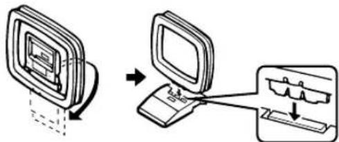
Insert the batteries in the correct direction by aligning the + and - marks on the batteries with the polarity markings (+) and (-) inside the battery compartment.
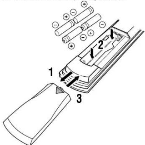
Press the part and slide off the battery compartment cover.
2 Insert the four supplied batteries (AAA, R03, UM-4) according to the polarity markings on the inside of the battery compartment.
3 Slide the cover back on so that it snaps into place.
Notes on batteries
- Change all of the batteries if you notice a decrease in the operating range of the remote control, that the indicator does not flash, or the light becoming dim.
- Do not use old batteries together with new ones.
- Do not use different types of batteries (such as alkaline and manganese batteries) together. Read the packaging carefully as these different types of batteries may have the same shape and color.
- If the batteries have leaked, dispose of them immediately. Avoid touching the leaked material or letting it come into contact with clothing, etc. Clean the battery compartment thoroughly before installing new batteries.
If the remote control is without batteries for more than 2 minutes, or if exhausted batteries remain in the remote control, the contents of the memory may be cleared. When the memory is cleared, insert new batteries, set up the manufacturer code that may have been cleared.
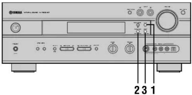
CONTROLS AND FUNCTIONS
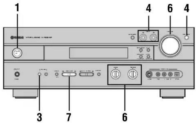
Front panel
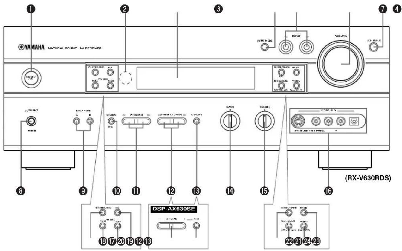
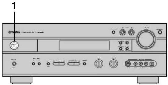
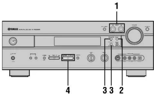
1 STANDBY/ON
Turns this unit on, or set it to the standby mode. When you turn this unit on, you will hear a click and there will be a 4 to 5-second delay before this unit can reproduce sound.
Standby mode
In this mode, this unit will consume a small amount of power in order to receive infrared-signals from the remote control.
Remote control sensor
Receives signals from the remote control.
3 Front panel display
Shows information about the operational status of this unit.
4 INPUT MODE
Sets the priority for the types of input signals (AUTO, DTS, ANALOG) to receive when one component is connected to two or more input jacks. Priority cannot be set when 6CH INPUT is selected as the input source.
5 INPUT<1/D
Selects the input source you want to listen to or watch.
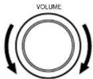
6 VOLUME
Controls the output level of all audio channels. This does not affect the OUT (REC) level.
6CH INPUT
Selects the audio source connected to the 6CH INPUT jacks. This audio takes priority over the source selected with INPUT < 1 / > (or the input selector buttons on the remote control).
SILENT (PHONES jack)
Allows you enjoy DSP effect for private listening with headphones. When you connect headphones, no signals are output to the speakers or the OUTPUT jacks.
9 SPEAKERS A/B
Turns the set of main speakers connected to the A and/or B terminals on or off.
10STEREO/EFFECT
Switches between normal stereo and DSP effect reproduction. When STEREO is selected, 2-channel signals are directed to the main left and right speakers without effect sounds and all Dolby Digital and DTS signals (except the LFE channel) are mixed down to the main left and right speakers.
1 PROGRAM
Selects the DSP program.
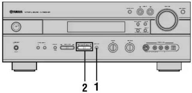
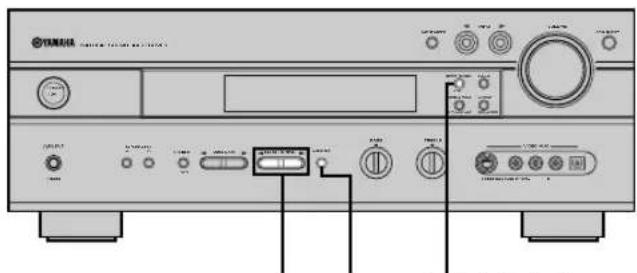
RX-V630RDS PRESET/TUNING
Selects preset station numbers 1 to 8 when the colon (·) appears in the front panel display.
Selects the tuning frequency when the colon (·) does not appear.
DSP-AX630SE SET MENU -/+
Adjusts the setting on the SET MENU.
RX-V630RDS A/B/C/D/E
Selects preset station groups A to E.
DSP-AX630SE NEXT
Selects the SET MENU mode.
14BASS
Adjusts the low-frequency response for the main left and right channels.
Turn right to increase or turn left to decrease the low-frequency response.
15TREBLE
Adjusts the high-frequency response for the main left and right channels.
Turn right to increase or turn left to decrease the high-frequency response.
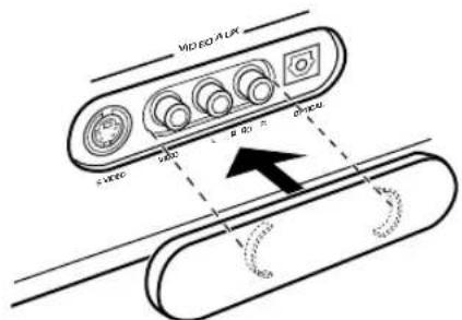
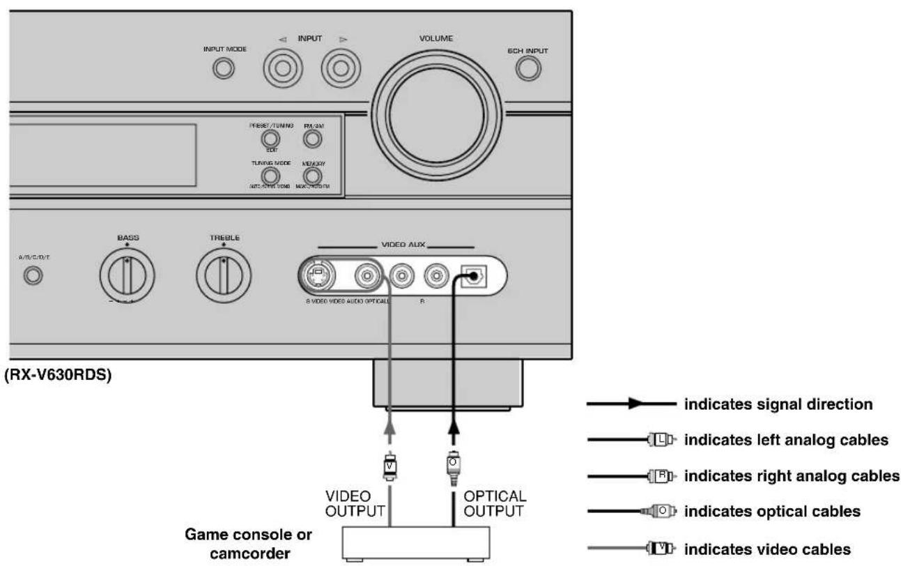
16VIDEO AUX jacks
Inputs for audio and video signals from a portable external source (game console, etc.). Set the input source to V-AUX to enjoy source signals from these jacks.
When the VIDEO AUX jacks on the front panel are not used, you can attach the provided front VIDEO AUX jack cap as shown in the illustration. When the cap is not attached, be sure retain it carefully.
RX-V630RDS
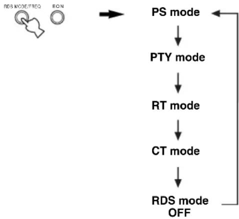
17RDS MODE/FREQ
When an RDS station is received, press this button to change the display mode among the PS mode, PTY mode, RT mode, CT mode (if the station offers those RDS data service) and/or frequency display mode in turn.
18PTY SEEK MODE
Press this button to set the unit in the PTY SEEK mode.
19PTY SEEK START
Press this button to begin searching for a station after the desired program type has been selected in the PTY SEEK mode.
20EON
Press this button to select the desired program type (NEWS, INFO, AFFAIRS, SPORT) when you want to tune in to a radio program of that type automatically.
2 PRESET/TUNING (EDIT)
Switches the function of PRESET/TUNING < 1 / > between selecting a preset station number and tuning (the colon (:)) turns on or off).
This button is also used to exchange the assignment of two preset stations with each other.
2TUNING MODE (AUTO/MAN'L MONO)
Switches the tuning mode between automatic and manual.
23MEMORY (MAN'L/AUTO FM)
Stores the current station in the memory.
2FM/AM
Switches the reception band between FM and AM.
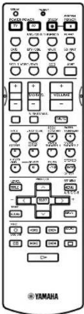
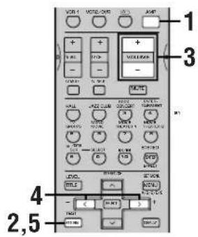
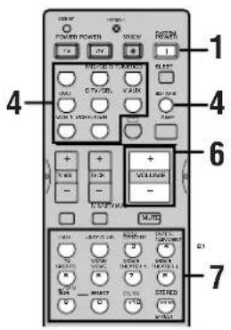
Remote control
This section describes the remote control controls and their functions. Make sure that the AMP mode is selected before starting operation. See "REMOTE CONTROL FEATURES" on pages 48 to 50.
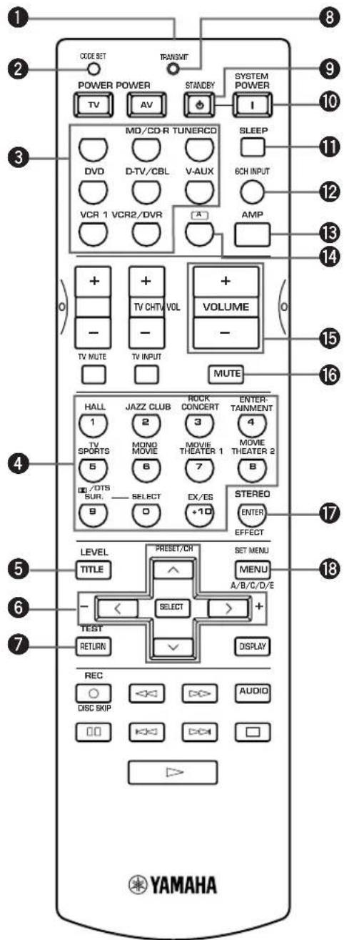
Infrared window
Outputs infrared control signals. Aim this window at the component you want to operate.
CODE SET
Used when setting up the manufacturer code (see page 49).
Input selector buttons
Select the input source and set the remote control to operate the selected source component.
DSP program
Select DSP programs for the AMP position. Press a button repeatedly to select a DSP program within that group.
LEVEL
Selects the effect speaker channel to be adjusted.
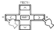
6Multi control section
Used when changing the setting and to implement the settings.
7TEST
Outputs the test tone to adjust the speaker levels.
TRANSMIT indicator
Flashes while the remote control is sending signals.
STANDBY
Sets this unit in the standby mode.
10SYSTEM POWER
Turns on the power of this unit.
1SLEEP
Sets the sleep timer.
6CH INPUT
Selects the audio source connected to the 6CH INPUT jacks.
13AMP
Sets the remote control to the AMP mode for controlling this unit.
14A
Sets the remote control to operate other component (not necessarily connected to this unit) without changing this unit's input source.
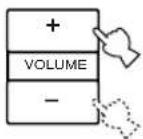
15VOLUME+/-
Increases or decreases the volume level.
16MUTE
Mutes the sound. Press again to restore the audio output to the previous volume level.
17STEREO/EFFECT
Switches between normal stereo and DSP effect reproduction. When STEREO is selected, 2-channel signals are directed to the main left and right speakers without effect sounds and all Dolby Digital and DTS signals (except the LFE channel) are mixed down to the main left and right speakers.
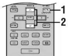
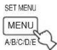
SET MENU
Selects the SET MENU mode.
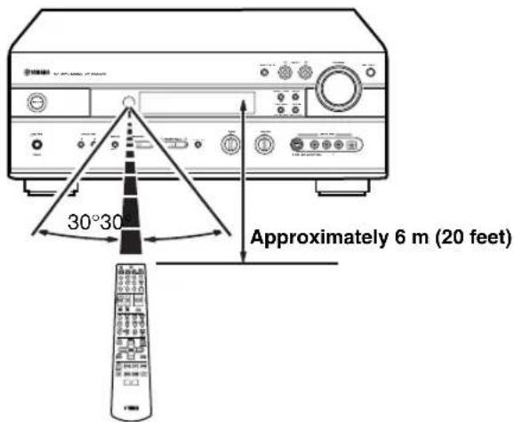
Using the remote control
The remote control transmits a directional infrared beam. Be sure to aim the remote control directly at the remote control sensor on the main unit during operation.
■Handling the remote control
- Do not spill water or other liquids on the remote control.
- Do not drop the remote control.
-
Do not leave or store the remote control in the following types of conditions:
-
high humidity or temperature such as near a heater, stove or bath;
-dustyplaces;or - in places subject to extremely low temperatures.
Front panel display
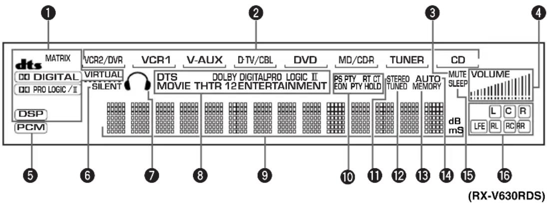
1 Processor indicators
Lights up when the dts, DIGITAL, VIRTUAL, PRO LOGIC/II or DSP are activated.
MATRIX lights up when the Dolby Digital EX decoder or the DTS-ES compatible decoder is activated.
Input source indicator
Shows the current input source with a cursor.
3 MUTE indicator
Flashes while the MUTE function is on.
VOLUME level indicator
Indicates the volume level.
PCM indicator
Lights up when this unit is reproducing PCM (pulse code modulation) digital audio signals.
6 SILENT indicator
Lights up when headphones are connected while the digital sound field processor is on.
7 Headphones indicator
Lights up when headphones are connected.
DSP program indicators
The name of the selected DSP program lights up when the ENTERTAINMENT, MOVIE THEATER 1, MOVIE THEATER 2 or DTS SURROUND DSP program is selected.
Multi-information display
Shows the current DSP program name and other information when adjusting or changing settings.
RX-V630RDS
10 RDS indicator
The name(s) of the RDS data offered by the currently received RDS station light(s) up.
EON indicator lights up when an RDS station that offers the EON data service is being received.
PTY HOLD indicator lights up while searching for stations in the PTY SEEK mode.
1STEREO indicator
Lights up when this unit is receiving a strong signal for an FM stereo broadcast while the "AUTO" indicator is lit.
TUNED indicator
Lights up when this unit is tuned to a station.
13 MEMORY indicator
Flashes to show a station can be stored.
AUTOindicator
Shows that this unit is in the automatic tuning mode.
SLEEP indicator
Lights up while the sleep timer is on.
16 Input channel indicator
Indicates the channel components of input signals being received.
SPEAKER SETUP
Speakers
This unit has been designed to provide the best soundfield quality with a 6-speaker system, using main left and right speakers, rear left and right speakers, a center speaker, and a rear center speaker. If you use different brands of speakers (with different tonal qualities) in your system, the tone of a moving human voice and other types of sound may not shift smoothly. We recommend that you use speakers from the same manufacturer or speakers with the same tonal quality.
The main speakers are used for the main source sound plus effect sounds. They will probably be the speakers from your present stereo system. The rear speakers are used for effect and surround sounds. The center speaker is for the center sounds (dialog, vocals, etc.). The rear center speaker supplements the rear (left and right) speakers and provides for more realistic front-to-back transitions.
The main speakers should be high-performance models and have enough power-handling capacity to accept the maximum output of your audio system. The other speakers do not have to be equal to the main speakers. For precise sound localization, however, it is ideal to use the models of equivalent performance with the main speakers.
■Use of a subwoofer expands your sound field
It is also possible to further expand your system with the addition of a subwoofer. The use of a subwoofer is effective not only for reinforcing bass frequencies from any or all channels, but also for reproducing the LFE (low-frequency effect) channel with high fidelity when playing back Dolby Digital or DTS signals. The YAMAHA Active Servo Processing Subwoofer System is ideal for natural and lively bass reproduction.
Speaker placement
Refer to the following diagram when you place the speakers.
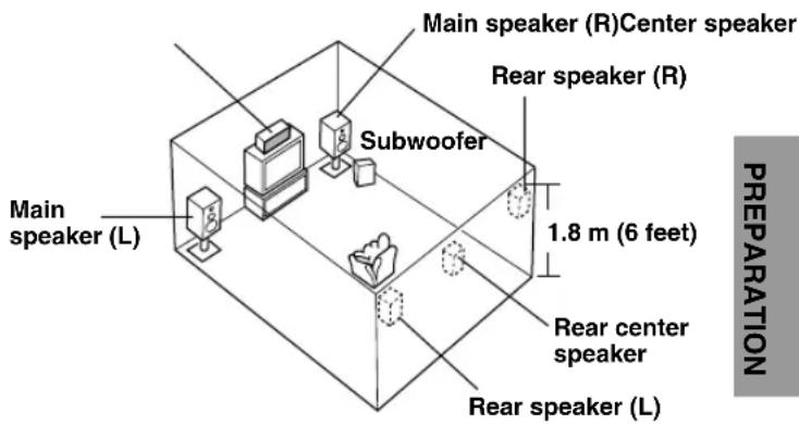
Main speakers
Place the main left and right speakers an equal distance from the ideal listening position. The distance between each speaker and each side of the video monitor should also be the same.
Center speaker
Align the front face of the center speaker with the front face of your video monitor. Place the speaker as close to the monitor as possible (such as directly over or under the monitor) and centrally between the main speakers.
Rear speakers
Place these speakers behind your listening position, facing slightly inwards, nearly 1.8m (6 feet) above the floor.
■Rear center speaker
Place the rear center speaker in the center between the rear left and right speakers at the same height from the floor as the rear speakers.
Subwoofer
The position of the subwoofer is not so critical, because low bass sounds are not highly directional. But it is better to place the subwoofer near the main speakers. Turn it slightly toward the center of the room to reduce wall reflections.
Note
- If you do not use any of effect speakers (rear, center and/or rear center), change the settings of SPEAKER SET items at the SET MENU to designate the signals to other terminals you connect speakers to.
CAUTION
Use magnetically shielded speakers. If this type of speakers still creates the interference with the monitor, place the speakers away from the monitor.
Connecting the speakers
Be sure to connect the left channel (L), right channel (R), "+" (red) and "-" (black) properly. If the connections are faulty, no sound will be heard from the speakers, and if the polarity of the speaker connections is incorrect, the sound will be unnatural and lack bass.
CAUTION
- Use speakers with the specified impedance shown on the rear panel of this unit.
- Do not let the bare speaker wires touch each other or any metal part of this unit. This could damage this unit and/or the speakers.
If necessary, use the SET MENU to change the speaker mode settings according to the number and size of the speakers in your configuration after you finish connecting your speakers.
■Speaker cables
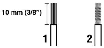
A speaker cord is actually a pair of insulated cables running side by side. One cable is colored or shaped differently, perhaps with a stripe, groove or ridge.
1 Remove approximately 10mm (3/8") of insulation from each of the speaker cables.
Twist the exposed wires of the cable together to prevent short circuits.
Connecting to the SPEAKERS terminals
Red: positive (+) Black: negative (-)
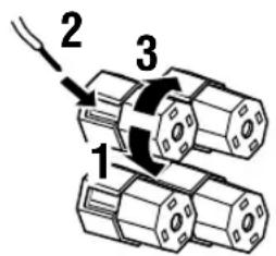
1Unscrew the knob.
2 Insert one bare wire into the hole in the side of each terminal.
3 Tighten the knob to secure the wire.
■MAIN SPEAKERS terminals
One or two speaker systems can be connected to these terminals. When using only one speaker system, it can be connected to either the MAIN A or the MAIN B terminals.
■REAR SPEAKERS terminals
A rear speaker system can be connected to these terminals.
CENTER SPEAKER terminals
A center speaker can be connected to these terminals.
REAR CENTER SPEAKER terminals
A rear center speaker can be connected to these terminals.
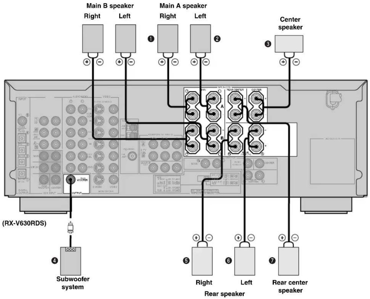
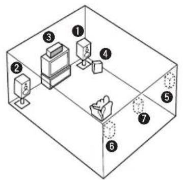
The diagram shows the speaker layout in the listening room.
SUBWOOFER jack
When using a subwoofer with built-in amplifier, including the YAMAHA Active Servo Processing Subwoofer System, connect the input jack of the subwoofer system to this jack. Low bass signals distributed from the main, center and/or rear channels are directed to this jack in accordance with your SPEAKER SET selections. The LFE (low-frequency effect) signals generated when Dolby Digital or DTS is decoded are also directed to this jack in accordance with your SPEAKER SET selections.
Notes
The cut-off frequency of the SUBWOOFER jack is 90Hz
- If you do not use a subwoofer, designate the signals to the main left and right speakers by changing the setting of SPEAKER SET item "IE BASS" on the SET MENU to MAIN.
- Use the control on the subwoofer to adjust its volume level. It is also possible to adjust the volume level by using this unit's remote control (see "ADJUSTING THE LEVEL OF THE EFFECT SPEAKERS" on page 51).
■IMPEDANCE SELECTOR switch
WARNING
Do not change setting of the IMPEDANCE SELECTOR switch when the power of this unit is on, this may damage the unit. If this unit fails to turn on when STANDBY/ON (or SYSTEM POWER) is pressed, the IMPEDANCE SELECTOR switch may not be fully slid to either position. If so, slide the switch all the way to either position when this unit is in the standby mode.
Select the switch position (left or right) according to the impedance of the speakers in your system. Be sure to move this switch only when this unit is in the standby mode.
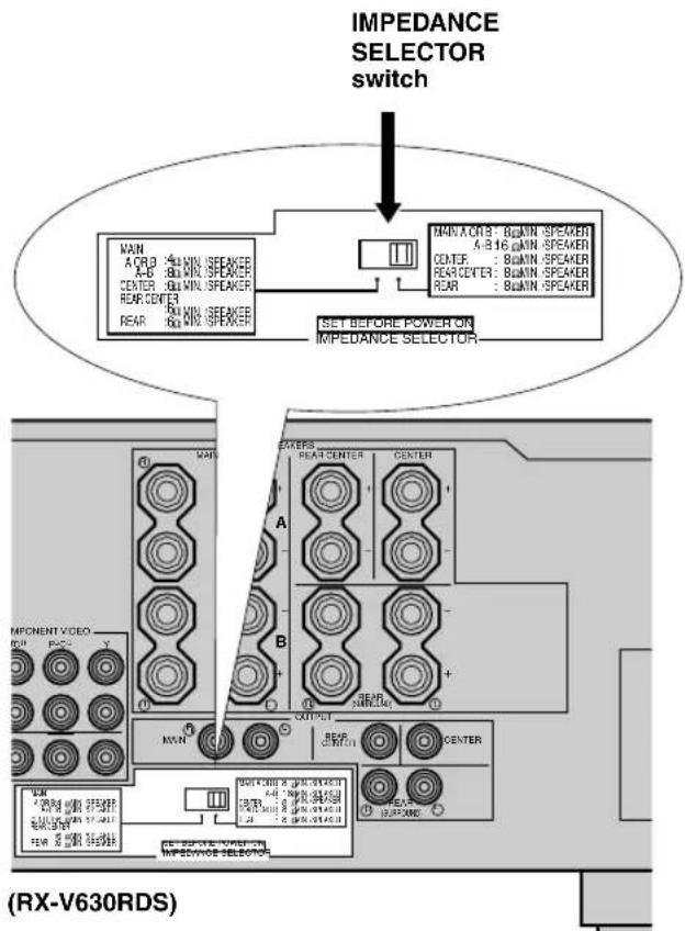
| Switch position | Speaker | Impedance level |
| Left | Main | If you use one set of main speakers, the impedance of each speaker must be 4 Ω or higher. If you use two sets of main speakers, the impedance of each speaker must be 8 Ω or higher. |
| Center | The impedance must be 6 Ω or higher. | |
| Rear Center | The impedance must be 6 Ω or higher. | |
| Rear | The impedance of each speaker must be 6 Ω or higher. | |
| Right | Main | If you use one set of main speakers, the impedance of each speaker must be 8 Ω or higher. If you use two sets of main speakers, the impedance of each speaker must be 16 Ω or higher. [Canada model only] The impedance of each speaker must be 8 Ω or higher. |
| Center | The impedance must be 8 Ω or higher. | |
| Rear Center | The impedance must be 8 Ω or higher. | |
| Rear | The impedance of each speaker must be 8 Ω or higher. |
CONNECTIONS
Before connecting components
CAUTION
Do not connect this unit or other components to the mains power until all connections between the components have been completed.
- Be sure all connections are made correctly, that is to say L (left) to L, R (right) to R, “+” to “+” and “-” to “-”. Some components require different connection methods and have different jack names. Refer to the operation instructions for each component to be connected to this unit.
- When you connect other YAMAHA audio components (such as a tape deck, MD recorder and CD player or changer), connect them to the jack with the same number labels as 1, 3, 4 etc. YAMAHA applies this labeling system to all its products.
After you have completed all connections, check them again to make sure they are correct. - The name of jack corresponds to input selector.
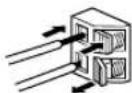
Connecting to digital jacks
This unit has digital jacks for direct transmission of digital signals through either coaxial or fiber optic cables. You can use the digital jacks to input PCM, Dolby Digital and DTS bitstreams. To enjoy multi-channel sound track of DVD software, etc. with DSP effect, you need to make digital connection. All digital input jacks are acceptable for 96-kHz sampling digital signals.
Note
- The OPTICAL jacks on this unit conform to the EIA standard. If you use a fiber optic cable that does not conform to this standard, this unit may not function properly.
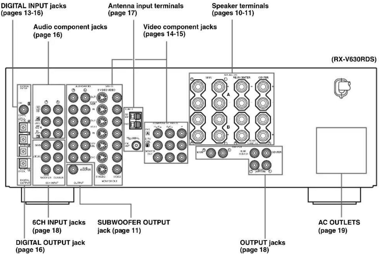
Connecting video components
Refer to the connection examples on the next page.
Types of video jacks
There are three types of video jacks as follows:
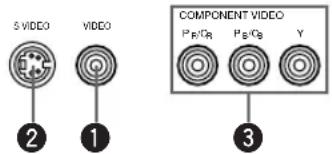
VIDEO jack
Conventional composite video signal.
SVIDEO jack
Transmits color and luminance separately and achieves high-quality color reproduction.
3 COMPONENTVIDEOjacks
Transmit color difference (P_B / C_B,P_R / C_R) and luminance separately and provide the best quality picture.
Each type of video jack works independently. Signals input through the composite video, S-video and component jacks are only output through the corresponding composite video, S-video, and component jacks.
- Use a commercially available cable specified for connecting each type of jacks.
- The description of the component video jacks may differ depending on the component (e.g. Y, G, C/R/Y, P, P/R/Y, B-Y, R-Y etc.). When using these jacks, refer also to the operation instructions for the component being connected.
Connecting a video monitor
Connect the video input jack on your video monitor to the MONITOR OUT VIDEO jack.
Note
- If you connect this unit with a source component using S-video (or Component video) jacks, you also need to connect your video monitor using S-video (or Component video) jacks.
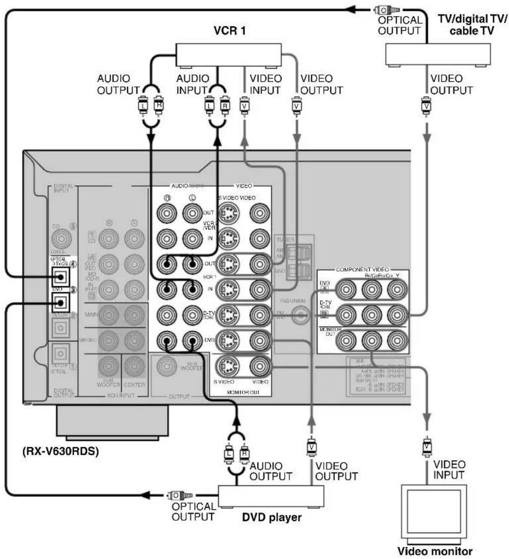
Connecting a DVD player/digital TV/cable TV
Connect the optical digital audio signal output jack on your component to the DIGITAL INPUT jack and connect the video signal output jack on the component to the VIDEO jack on this unit.
Then connect AUDIO jacks on your component to the AUDIO jacks on this unit.

- If your video component has an S-video output or component video output, connect the S-video signal output jack on the component to the SVIDEO jack or connect the component video signal output jacks on the component to the COMPONENTVIDEO jacks.
- The AUDIO jacks are available for a video component which does not have optical digital output jack. However, multi-channel reproduction cannot be obtained with audio signals input from AUDIO jacks.
Connecting a game console or camcorder
Connect the optical digital audio signal output jack on your video component to the OPTICAL jack on the front panel and connect video signal output jack on the component to the VIDEO jack on the front panel.

- If your video component has an S-video output, connect the S-video signal output jack on the component to the SVIDEO jack.
- The AUDIO jacks are available for a video component such as a camcorder which does not have optical digital output jack.
Connecting a VCR or DVR (digital video recorder)
Connect the audio signal input jacks on your video component to the AUDIO OUT jacks and connect the video signal input jack on the video component to theVIDEO OUT jack on this unit for picture recording. Connect the audio signal output jacks on your component to the AUDIO IN jacks and connect the video signal output jack on the component to theVIDEO IN jack on this unit to play a source from your recording component. Second VCR or digital video recorder can be connected using VCR 2/DVR jacks.

- If your video component has an S-video input, connect the S-video signal input jack on the component to the SVIDEO OUT jack.
- If your video component has an S-video output, connect the S-video signal output jack on the component to the SVIDEO IN jack.
Notes
- Once you have connected a recording component to this unit, keep its power turned on while using this unit. If the power is off, this unit may distort the sound from other components.
- S-video and component video signals pass independently through this unit's video circuit. Make sure to connect this unit to both a source component and a recording component using the video jacks of the same system.
Connecting audio components
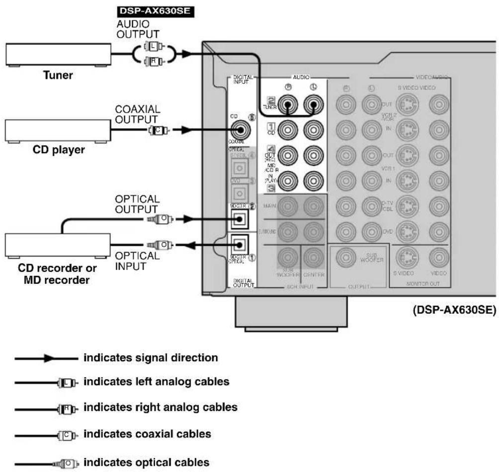
Connecting a CD player
Connect the coaxial digital output jack on your CD player to the DIGITAL INPUT CD jack.

- The AUDIO jaacks are available for a CD player which does not have coaxial digital output jack.
Connecting a CD recorder or MD recorder
Connect the optical digital signal input jack on your CD recorder or MD recorder to the DIGITAL OUTPUT MD/CD-R jack for digital recording.
Connect the optical digital output jack on your CD recorder or MD recorder to the DIGITAL INPUT MD/CD-R jack to play a source from your recording component.

- The AUDIO jacks are available for an CD recorder or MD recorder which does not have optical digital input or output jack.
Notes
- Once you have connected a recording component to this unit, keep its power turned on while using this unit. If the power is off, this unit may distort the sound from other components.
- DIGITAL OUTPUT jack and analog OUT (REC) jacks are independent. Only digital signals are output from DIGITAL OUTPUT jack and analog signals from OUT (REC) jacks.

DSP-AX630SE
Connecting a tuner
Connect the output jacks on your tuner to the TUNER jacks.
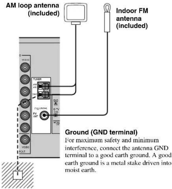
Connecting the antennas RX-V630RDS
Both AM and FM indoor antennas are included with this unit. In general, these antennas should provide sufficient signal strength.
Connect each antenna correctly to the designated terminals.
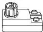
75-ohm/300-ohm antenna adapter (U.K. model)
1
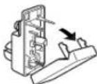
Open the cover of the included 75-ohm/300-ohm antenna adapter.
2
11 (7/16)
8 (5/16) Unit:
6 (1/14) mm (inch)
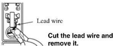
Cut the external sleeve of the 75-ohm coaxial cable and prepare it for connection.
3
4
Clamp with pliers.
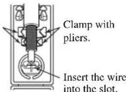
Insert the cable wire into the slot, and clamp it with pliers.
5
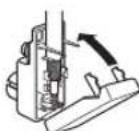
Snap the cover into place.
Connecting the AM loop antenna
1 Set up the AM loop antenna, then connect it.
Press and hold the tab to insert the AM loop antenna lead wires into the AM ANT and GND terminals.
3 Orient the AM loop antenna for the best reception.

Notes
-
The AM loop antenna should be placed away from this unit.
-
The AM loop antenna should always be connected, even if an outdoor AM antenna is connected to this unit.
A properly installed outdoor antenna provides clearer reception than an indoor one. If you experience poor reception quality, an outdoor antenna may improve the quality. Consult the nearest authorized YAMAHA dealer or service center about the outdoor antennas.
Connecting an external amplifier
If you want to increase the power output to the speakers, or want to use another amplifier, connect an external amplifier to the OUTPUT jacks as follows.
Note
- When RCA pin plugs are connected to the OUTPUT jacks for output to an external amplifier, signals are output from the SPEAKERS terminals as well.
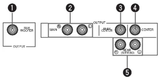
SUBWOOFER jack
When using a subwoofer with built-in amplifier, including the YAMAHA Active Servo Processing Subwoofer System, connect the input jack of the subwoofer system to this jack. Low bass signals distributed from the main, center and/or rear channels are directed to this jack in accordance with your SPEAKER SET selections. The LFE (low-frequency effect) signals generated when Dolby Digital or DTS is decoded are also directed to this jack in accordance with your SPEAKER SET selections.
Notes
The cut-off frequency of the SUBWOOFER jack is 90Hz
- If you do not use a subwoofer, designate the signals to the main left and right speakers by changing the settings of SPEAKER SET item "1E BASS" on the SET MENU.
- Use the control on the subwoofer to adjust its volume level. It is also possible to adjust the volume level by using this unit's remote control (see "ADJUSTING THE LEVEL OF THE EFFECT SPEAKERS" on page 51).
2MAINjacks
Main channel line output jacks.
Note
- The signals output through these jacks are affected by the BASS and TREBLE settings.
REAR CENTER jack
Rear center channel line output jack.
4CENTER jack
Center channel line output jack.
REAR (SURROUND) jacks
Rear channel line output jacks.
Connecting an external decoder
This unit is equipped with 6 additional input jacks (MAIN left and right, CENTER, SURROUND left and right, and SUBWOOFER) for discrete multi-channel input from an external decoder, sound processor, or pre-amplifier.
Connect the output jacks on your external decoder to the 6CH INPUT jacks. Be sure to match the left and right outputs to the left and right input jacks for the main and surround channels.
Notes
- When you select 6CH INPUT as the input source, this unit automatically turns off the digital sound field processor, and you cannot listen to DSP programs.
- When you select 6CH INPUT as the input source, settings of "1 SPEAKER SET" on the SET MENU do not apply (except for "1F MAIN Lv").
Connecting the power supply cords
(Europe model)
Connecting the AC power cord
Plug in this unit to the wall outlet.
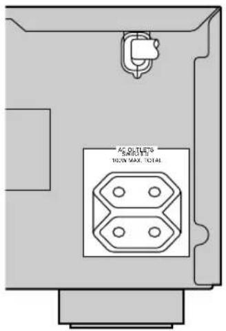
AC OUTLETS (SWITCHED)
U.S.A., Canada, China, Europe, Singapore and General models 2 OUTLETS U.K. and Australia model 1 OUTLET Use these outlets to connect the power cords from your components to this unit. The power to the AC OUTLETS is controlled by this unit's STANDBY/ON (or SYSTEM POWER and STANDBY). These outlets will supply power to any source component connected to this unit whenever this unit is turned on. The maximum power (total power consumption of components) that can be connected to the AC OUTLETS varies depending on the area which it was purchasing.
China and General models 50 W Other models 100 W
Turning on the power
When all connections are complete, turn on the power of this unit.
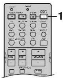
1 Press STANDBY/ON (SYSTEM POWER on the remote control) to turn on the power of this unit.

Front panel
or

Remote control
The level of the main volume, and then the current DSP program name appear on the front panel display.
2 Turn on the video monitor connected to this unit.
SPEAKER MODE SETTINGS
This unit has 6 SPEAKER SET items on the SET MENU that you must set according to the number of speakers in your configuration and their size. The following table summarizes these SPEAKER SET items, and shows the initial settings as well as other possible settings.
If the initial settings shown in the following table are not appropriate for your speaker configuration, see "1 SPEAKER SET" on pages 43-45 to change the settings.
Summary of SPEAKER SET items 1A through 1F
| Item | Description | Possible settings (default setting indicated in bold) |
| 1A CENTER | Sets center speaker availability and size. | LRG/SML/NON |
| 1B MAIN | Sets main speaker size. | LARGE/SMALL |
| 1C REAR LR | Sets rear L/R speakers availability and size. | LRG/SML/NON |
| 1D REAR CT | Sets rear center speaker availability and size. | LRG/SML/NON |
| 1E BASS | Sets the speaker(s) to be used to output low bass signals. | SWFR/Main/BOTH |
| 1F MAIN Lv | Sets the main speaker level. | Nrm (Normal)/-10 dB |
This section explains how to adjust speaker output levels using the test tone generator. When this adjustment is complete, the output level heard at the listening position should be the same from each speaker. This is important for best performance of the digital sound field processor, and the various decoders (Dolby Digital, Dolby Pro Logic, Dolby Pro Logic II and DTS).
Note
- Since this unit cannot enter the test mode while headphones are connected to this unit, be sure to unplug the headphones from the PHONES jack when using the test tone.
Before you begin
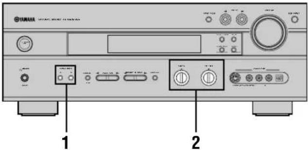
Press SPEAKERS A or B to select the main speakers to be used.

If you are using two sets of the main speakers, press both A and B.
2 Set the BASS and TREBLE controls on the front panel to the center position.


Using the test tone
Use the test tone to balance the output levels of the speakers. The adjustment of each speaker output level should be made at your listening position using the remote control.
1Press AMP.

Press TEST to output the test tone.

3 Adjust the volume of this unit so you can hear the test tone.
The test tone is heard (in order) from the main left speaker, center speaker, main right speaker, rear right speaker, rear center, rear left speaker, and the subwoofer. The tone is produced for 2.5 seconds from each speaker.
Front panel
or
Remote control
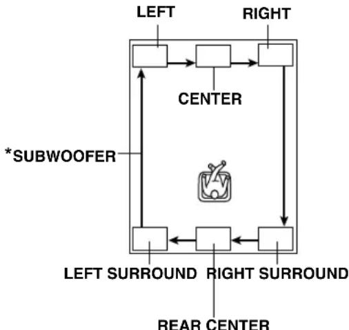
- Subwoofer test tone is output after the rear left speaker (LEFT SURROUND).
The front panel display shows which speaker is outputting the test tone.
Note
- If the test tone cannot be heard, turn down the volume, set this unit to standby mode and check the speaker connections.
4 Adjust the level of the effect speakers using / so that it matches the level of the main speakers. While adjusting, the test tone is heard from the selected speaker.
Note
To adjust the level of the main speakers, use VOLUME knob (or VOLUME + / - on the remote control).
When adjustment is complete, press TEST to stop the test tone.

Notes
- If "1A CENTER" on the SET MENU is set to NON, the center channel sound is automatically output from the main left and right speakers.
- If "1C REAR LR" on the SET MENU is set to NON, the output level of the rear left, right and center speakers cannot be adjusted in step 4. The test tone will be circulated skipping the rear left and right speakers and the rear center speaker.
- If "1D REAR CT" on the SET MENU is set to NON, the output level of the rear center speaker cannot be adjusted in step 4. The test tone will be circulated skipping the rear center speaker.
- If "1E BASS" on the SET MENU is set to MAIN, the test tone will be circulated skipping the subwoofer.
中
- It is not necessary to readjust the speaker levels once they are set (as long as you do not change the speakers). You can enjoy listening to or watching the input source at the desired volume simply by adjusting the VOLUME knob (or VOLUME +/- on the remote control).
- If the output level of the effect speakers (center, rear left, rear right, and rear center) cannot be increased enough to match the level of the main speakers, set "1F MAIN Lv" on SET MENU to -10dB (see page 45). This setting decreases the main speaker output level to about one-third of the normal level. After you have set "1F MAIN Lv" on the SET MENU to -10dB , adjust the levels for the center and rear speakers again.
BASIC PLAYBACK
1 Press STANDBY/ON (SYSTEM POWER on the remote control) to turn on the power.

Front panel


Remote control
2Turn on the video monitor connected to this unit.
3 Press SPEAKERS A or B to select the main speakers to be used.
If you are using two sets of main speakers, press both A and B.

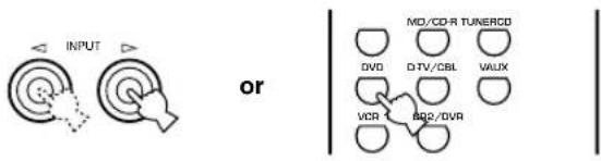
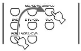
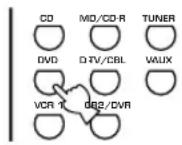
4 Press INPUT / repeatedly (one of the input selector buttons on the remote control) to select the input source.
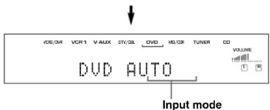
The selected input source name and input mode appear on the front panel display for a few seconds.
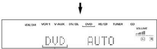
Front panel
Remote control
Selected input source
To select the audio source connected to the 6CH INPUT jacks
(When combining with a video source)
- You need to select the input to which the video source component is connected before selecting audio source. Press 6CH INPUT until "6CH INPUT" appears on the front panel display.

6CH INPUT
Front panel


6CH INPUT
Remote control

6CH INPUT
Note
- If "6CH INPUT" is shown on the front panel display, no other source can be played. To select another input source, first press 6CH INPUT to turn off "6CH INPUT" from the front panel display.
5 Start playback or select a broadcast station on the source component.
Refer to the operation instructions for the component.
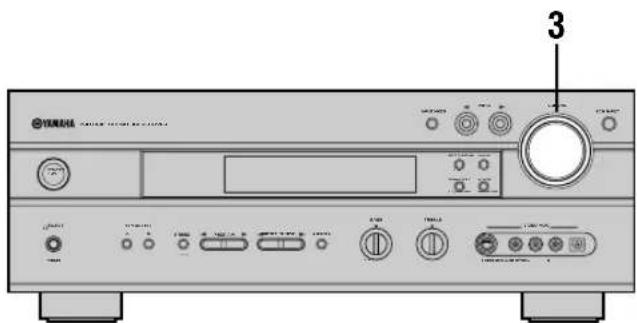
6 Adjust the volume to the desired level.
The volume level is displayed digitally.
Example: -70 dB
Control range: VOLUME MUTE (minimum) to 0 dB (maximum)
The volume level indicator also shows the current volume level as a bar graph.
If desired, use BASS and TREBLE. These controls only effect the sound from the main speakers.
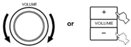


or
Remote control
Front panel
Notes
- If you increase or decrease the high-frequency or the low-frequency sound to an extreme level, the tonal quality from the center and rear speakers may not match that of the main left and right speakers.
- If you have connected a recording component to the VCR 1 OUT, VCR 2/DVR OUT, or MD/CD-R OUT jacks, and you notice distortion or low volume during playback of other components, try turning the recording component on.
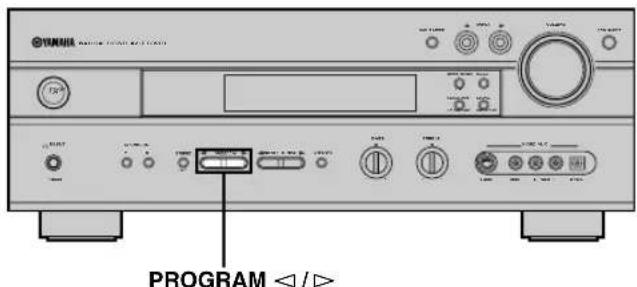
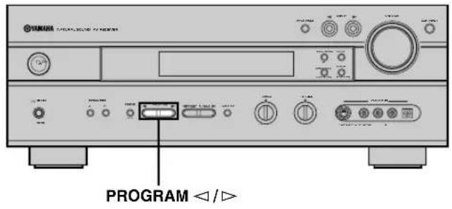
7 Select a DSP program if desired.
Use PROGRAM / (DSP program buttons on the remote control) to select a DSP program. See pages 29 to 33 for details about DSP programs.
When using the remote control, press AMP before selecting a DSP program.

or
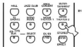
Front panel
Remote control
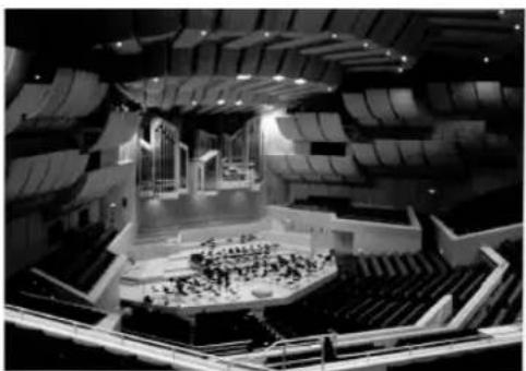
■BGV (background video) function
The BGV function allows you to enjoy video images from a video source together with sounds from an audio source. For example, you can enjoy listening to classical music while having beautiful scenery from a video source on the video monitor.
Select a source from the video group, then select a source from the audio group using the input selector buttons on the remote control. BGV selections cannot be made with INPUT < / > on the front panel.
■To mute the sound
Press MUTE on the remote control.
To resume the audio output, press MUTE again.


- You can also cancel mute by pressing VOLUME +/-, etc.
- During muting, the "MUTE" indicator flashes on the front panel display.
■When you have finished using this unit
Press STANDBY/ON (STANDBY on the remote control) to set this unit in the standby mode.

Front panel
or

Remote control
Input modes and indications
This unit comes with a variety input jacks. You can select the type of input signals you desire.
Each time you turn on the power of this unit, the input mode is set according to "8 INPUT MODE" setting on the SET MENU (see page 47 for details).
Press INPUT MODE (the input selector button that you have pressed to select the input source on the remote control) repeatedly until the desired input mode is shown on the front panel display.

or
Remote control
Front panel
AUTO: In this mode, the input signal is selected automatically as follows:
1) Digital signal
2) Analog signal
DTS: In this mode, only the digital input signal encoded with DTS is selected, even if another signal is input at the same time.
ANALOG: In this mode, only the analog input signal is selected, even if a digital signal is input at the same time.
Notes
- When AUTO is selected, this unit automatically determines the type of signal. If this unit detects a Dolby Digital or DTS signal, the decoder automatically switches to the appropriate setting.
- When playing a disc encoded with Dolby Digital or DTS on some LD or DVD players, the sound output delays for a moment when playback resumes after a search because the digital signal is selected again.
- When playing a LD source that has not been digitally recorded, the sound may not be output for some LD players. In this case, set the input mode to ANALOG.
Notes on 96-kHz sampling digital signals
The digital input jacks of this unit can handle 96-kHz sampling digital signals. Note the following when 96-kHz sampling digital signal is input to this unit:
DSP programs cannot be selected.
Sound will be output as 2-channel stereo from only the main left and right speakers. (There may be sound output from the subwoofer depending on the SPEAKER MODE settings on the SET MENU.) Therefore, the level of the effect speakers cannot be adjusted while listening to such a source.
Notes on playing DTS-CD/LDs
- If the digital output data of the player has been processed in any way, you may not be able to perform DTS decoding even if you make a digital connection between this unit and the player.
- If you play a source encoded with a DTS signal and set the input mode to ANALOG, this unit may reproduce the noise of an unprocessed DTS signal. In this case, connect the source to a digital input jack and set the input mode to AUTO or DTS.
- If you switch the input mode to ANALOG while playing a source encoded with a DTS signal, this unit reproduces no sound.
-
If you play a source encoded with a DTS signal with the input mode set to AUTO;
-
This unit automatically switches to the DTS-decoding mode (The "dts" indicator lights up) after having detected the DTS signal. When playback of the DTS source is completed, the "dts" indicator may flash. While this indicator is flashing, only DTS source can be played. If you want to play a normal PCM source soon, set the input mode back to AUTO.
- When the input mode is set to AUTO and a search or skip operation is performed during playback of a DTS source, the "dts" indicator may flash. If this status continues for longer than 30 seconds, this unit will automatically switch from "DTS-decoding" mode to PCM digital signal input mode. The "dts" indicator will turn off.
Selecting a sound field program
You can enhance your listening experience by selecting a DSP program. For details about each program, see pages 29 to 33.
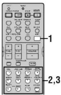
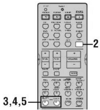
1Press AMP.

Press one of the DSP program buttons on the remote control to select the desired program.
The name of the selected program appears on the front panel display.
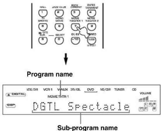
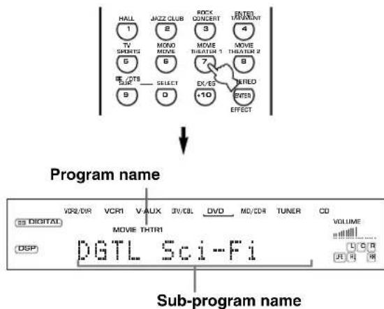
After selecting the desired program, press the same button repeatedly to select the desired sub-program if available.
Example: Pressing MOVIE THEATER 1 repeatedly switches the sub-program between "Sci-Fi" and "Spectacle".
Notes
- There are 9 programs with sub-programs available with this unit. However, the selection depends on the input signal format and not all sub-programs can be used with all input signal formats.
- The digital sound field processor cannot be used when a source connected to the 6CH INPUT jacks of this unit is selected or when 96-kHz sampling digital signals are input to this unit.
- The acoustics of your listening room affect the DSP program. Minimize the sound reflections in your room to maximize the effect created by the program.
- When you select an input source, this unit automatically selects the last DSP program used with that source.
- When you set this unit in the standby mode, the current source and DSP program are memorized and are automatically selected when you turn on the power again.
- If a Dolby Digital or DTS signal is input when the input mode is set to AUTO, the DSP program (No. 7-9) automatically switches to the appropriate decoding program.
- When a monaural source is being played with PRO LOGIC/Normal or PRO LOGIC/Enhanced, or PRO LOGIC Movie, no sound will be heard from the main speakers and the rear speakers. Sound can only be heard from the center speaker. (If "1A CENTER" on the SET MENU is set to NON, the center channel sound is output from the main speakers.)
中
- You can also select DSP program by pressing PROGRAM </D> on the front panel.
- Select a program based on your listening preference. Program names are just for reference.
■Selecting PRO LOGIC II
You can enjoy the 2-channel sources decoded into five or six discrete channels by selecting PRO LOGIC II in program No.9.
1 Select a 2-channel source and start playback on the source component.
2Press AMP.

3Press D/DTS SUR.
The previously selected sub program appears on the front panel display.
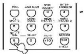
Remote control
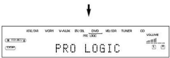
4 Press SELECT repeatedly to select the decoder; PRO LOGIC or PRO LOGIC II.
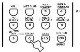
After selecting on the decoder (PRO LOGIC II), select the mode appropriate for the source by pressing D/DTS SUR.
The selection switches as follow; PRO LOGIC II Movie PRO LOGIC II Music
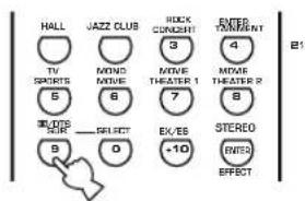

- You can select PRO LOGIC, PRO LOGIC II Movie, and PRO LOGIC II Music by pressing PROGRAM </D> on the front panel repeatedly.
■Playing Dolby Digital Surround EX or DTS ES software
Press EX/ES to turn on the Dolby Digital EX or DTS-ES compatible decoder.
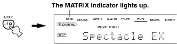
The display changes AUTO Matrix6.1 OFF each time the EX/ES button is pressed.
AUTO: This mode automatically switches Dolby Digital EX and DTS-ES compatible depending on the signal. Rear center speaker does not work for 5.1 channel sources.
Matrix6.1: This setting produces 6-channel playback of the input source using the Dolby Digital EX or DTS-ES compatible decoder. The rear center speaker can be used when playing a 5.1-channel source.
OFF: Rear center speaker does not work in this setting. (Except for when the DSP program "6ch" is selected.)
Notes
- No sound will be output from the rear center speaker if you have set "IC REAR LR" or "1D REAR CT" on the SET MENU to NON.
- The setting becomes AUTO once this unit turns into standby mode.
- Some Dolby Digital Surround EX or DTS ES software may not contain the signal that is necessary for this unit to switch to the Dolby Digital EX or DTS-ES compatible decoding mode. To turn on the decoder when playing such a source, select "Matrix6.1".
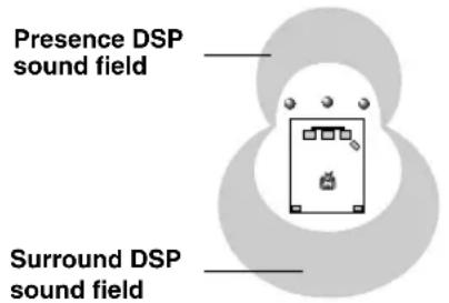
■Virtual CINEMA DSP
With Virtual CINEMA DSP, you can enjoy all DSP programs without rear speakers. It creates virtual speakers to reproduce a natural sound field.
You can listen to virtual CINEMA DSP by setting "1C REAR LR" in the SET MENU to NON. Sound field processing changes to VIRTUAL CINEMA DSP automatically.
Note
- This unit is not set in the virtual CINEMA DSP mode even if "IC REAR LR" is set to NON in the following cases:
- when the 6ch Stereo, DOLBY DIGITAL Normal, Pro Logic Normal, Pro Logic II or DTS Normal program is selected;
- when the sound effect is turned off;
- when 6CH INPUT is selected as the input source;
- when 96-kHz sampling digital signals are input to this unit;
- when using the test tone; or
- when connecting the headphones.
■SILENT CINEMA DSP
You can enjoy a powerful sound field similar to what you could expect from actual speakers with SILENT CINEMA DSP. You can listen to SILENT CINEMA DSP by connecting your headphones to the PHONES jack while the digital sound field processor is on. Enjoy all the DSP program using the headphones. The "SILENT" indicator lights up on the front panel display. (When sound effects are off, you listen to the source with normal stereo reproduction.)
Notes
- This feature is not available when 6CH INPUT is selected or 96-kHz sampling digital signals are input to this unit.
- The sound of LFE channel will be mixed and output from the headphone.
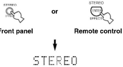
■Normal stereo reproduction
Press STEREO to turn off the sound effect for normal stereo reproduction.
Press STEREO again to turn the sound effect back on.
Notes
- If you turn off the sound effects, no sound is output from the center speaker, rear speakers, or rear center speaker.
- If you turn off the sound effects while a Dolby Digital or DTS signal is being output, the dynamic range of the signal is automatically compressed and the sounds of the center and rear speaker channels are mixed and output from the main speakers.
- The volume may be greatly reduced when you turn off the sound effects or if you set "4 D. RANGE" on the SET MENU to MIN. In this case turn on the sound effect.
- The sound of LFE channel will be directed to the main left and right or the subwoofer (or both) channels depending on the setting of "IE BASS" on the SET MENU.
中
During stereo reproduction, you can display information such as the type, format and sampling frequency of the signal input from the components connected to this unit.
(While playing a source)
1 Press AMP.
Press to display the information about the input signal.
DIGITAL SOUND FIELD PROCESSING (DSP)
Understanding sound fields
A sound field is defined as the "characteristic sound reflections of a particular space." In concert halls and other music venues, we hear early reflections and reverberations as well as the direct sound produced by the artist(s). The variations in the early reflections and other reverberations among the different music venues is what gives each venue its special and recognizable sound quality.
YAMAHA sent teams of sound engineers all around the world to measure the sound reflections of famous concert halls and music venues, and collect detailed sound field information such as the direction, strength, range, and delay time of those reflections. Then we stored this enormous amount of data in the ROM chips of this unit.
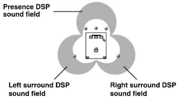
Recreating a sound field
Recreating the sound field of a concert hall or an opera house requires localizing the virtual sound sources in your listening room. The traditional stereo system that uses only two speakers is not capable of recreating a realistic sound field. YAMAHA's DSP requires four effect speakers to recreate sound fields based on the measured sound field data. The processor controls the strength and delay time of the signals output from the four effect speakers to localize the virtual sound sources and fully encompass the listener.
Hi-Fi DSP programs
The following list gives you a brief description of the sound fields produced by each of the DSP programs. Keep in mind that most of these are precise digital recreations of actual acoustic environments.
| No. | Program | Features |
| 1 | CONCERT HALL | A large round concert hall with a rich surround effect. Pronounced reflections from all directions emphasize the extension of sounds. The sound field has a great deal of presence, and your virtual seat is near the center, close to the stage. |
| 2 | JAZZ CLUB | This is the sound field at stage front in “The Bottom Line”, a famous New York jazz club, that seats up to 300 people. Its wide left to right seating arrangement offers a real and vibrant sound. |
| 3 | ROCK CONCERT | The ideal program for lively, dynamic rock music. The data for this program was recorded at LA’s “hottest” rock club. The listener’s virtual seat is at the center-left of the hall. |
| 4 | ENTERTAINMENT/Disco | This program recreates the acoustic environment of a lively disco in the heart of a big city. The sound is dense and highly concentrated. It is also characterized by a high-energy, “immediate” sound. |
| ENTERTAINMENT/6ch Stereo | Using this program increases the listening position range. This is a sound field suitable for background music at parties, etc. |
CINEMA-DSP
Sound design of CINEMA-DSP
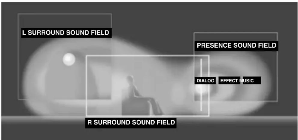
Filmmakers intend for the dialog to be located right on the screen, the effect sound a little farther back, the music spread even farther back, and the surround sound around the listener. Of course, all of these sounds must be synchronized with the images on the screen.
CINEMA-DSP is an upgraded version of YAMAHA DSP specially designed for movie soundtracks. CINEMA-DSP integrates the DTS, Dolby Digital, and Dolby Pro Logic surround sound technologies with YAMAHA DSP sound field programs to provide a surround sound field. It recreates comprehensive movie sound design in your audio room. In CINEMA-DSP sound field programs, YAMAHA's exclusive DSP processing is added to the Main left and right, and Center channels, so the listener can enjoy realistic dialogue, depth of sound, smooth transition between sound sources, and a surround sound field that goes beyond the screen.
When a DTS or Dolby Digital signal is detected, the CINEMA-Disp sound field processor automatically chooses the most suitable sound field program for that signal.
In addition to the DSP, this unit is equipped with a variety of precise decoders; Dolby Pro Logic decoder for Dolby Surround sources, Dolby Pro Logic II decoder for Dolby Surround and 2-channel sources, Dolby Digital/DTS decoder for multi-channel sources and Dolby Digital EX or DTS-ES compatible decoder for adding a rear center channel. You can select CINEMA-DSP programs to optimize these decoders and the DSP sound patterns depending on the input source.
The 6-channel soundtracks found on 70-mm film produce precise sound field localization and rich, deep sound without using matrix processing. This unit's MOVIE THEATER programs provide the same quality of sound and sound localization that 6-channel soundtracks do. The built-in Dolby Digital or DTS decoder brings the professional-quality sound designed for movie theaters into your home. With this unit's MOVIE THEATER programs, you can use Dolby Digital or DTS technology to recreate a dynamic sound that gives you the feeling of being in a public theater.
■Dolby Digital/DTS + DSP sound field effect
These programs use YAMAHA's tri-field DSP processing on each of the Dolby Digital or DTS signals for the front, left surround, and right surround channels. This processing enables this unit to reproduce the immense sound field and surround expression of a Dolby Digital-or DTS-equipped movie theater without sacrificing the clear separation of all channels.
■Dolby Digital EX/DTS-ES compatible + DSP sound field effect
These programs provide you with the maximum experience of the spacious surround effects by adding an extra rear center DSP sound field created from the rear center channel.
■Dolby Pro Logic + DSP sound field effect
Most movie software has 4-channel (left, center, right, and surround) sound information encoded by Dolby Surround matrix processing and stored on the left and right tracks. These signals are processed by the Dolby Pro Logic decoder. The MOVIE THEATER programs are designed to recreate the spaciousness and delicate nuances of sound that tend to be lost in the encoding and decoding processes.
■Dolby Pro Logic II
Dolby Pro Logic decodes Dolby Surround software into 5 discrete full-range channels (3 channels in front and 2 channels in rear). There are 2 modes; MOVIE for movies and MUSIC for 2-channel audio sources.
CINEMA-DSP programs
■For movie programs: No. 7 to 9
This unit automatically chooses the appropriate decoder and DSP sound field pattern according to the input signal format.
Table of Program Names for Each Input Format
| No. | Input Program | 2 channel | 5.1 channel | 6.1 channel * | ||
| Stereo | DOLBY DIGITAL | DTS | DOLBY DIGITAL EX | DTS-ES compatible | ||
| 7 | MOVIE THEATER 1 | 70 mm Spectacle | DGTL Spectacle | DTS Spectacle | Spectacle EX | Spectacle ES |
| 70 mm Sci-Fi | DGTL Sci-Fi | DTS Sci-Fi | Sci-Fi EX | Sci-Fi ES | ||
| 8 | MOVIE THEATER 2 | 70 mm Adventure | DGTL Adventure | DTS Adventure | Adventure EX | Adventure ES |
| 70 mm General | DGTL General | DTS General | General EX | General ES | ||
| 9 | DOLBY DIGITAL | — | Normal | — | Dolby D EX | — |
| — | Enhanced | — | Enhanced EX | — | ||
| DTS DIGITAL SUR | — | — | Normal | — | DTS-ES | |
| — | — | Enhanced | — | Enhanced ES | ||
| PRO LOGIC | Normal | — | — | — | — | |
| Enhanced | — | — | — | — | ||
| PRO LOGIC II | Movie | — | — | — | — | |
| Music | — | — | — | — | ||
- means the Dolby Digital EX decoder or the DTS-ES compatible decoder is ON.

- If a Dolby Digital signal or DTS signal is input when the input mode is set to AUTO, the DSP program will automatically switch to the Dolby Digital playback sound field or DTS playback sound field.
- If Dolby Digital Surround EX software or DTS ES software is played when AUTO is selected by pressing the EX/ES button on the remote control, the Dolby Digital EX or DTS-ES compatible decoder usually turns on and the corresponding DSP program is selected.
- EX/ES on the remote control can be used to play Dolby Digital or DTS 5.1 channel sources with the rear center speaker. In this case the program name changes to the corresponding name for 6.1 channel.
- When playing a 6.1 channel source with the Dolby Digital EX decoder or the DTS-ES compatible decoder turned off, the program name changes to the corresponding name for 5.1 channel.
Notes
- The "DSP" indicator does not light up when selecting program No. 9 except in Enhanced mode.
- When playing a monaural source with a CINEMA DSP program, the source signal is directed to the center channel, main and rear speakers output effect sounds.
The following list gives you a brief description of the sound fields produced by each of the DSP programs. Keep in mind that most of these are precise digital recreations of actual acoustic environments. Select the DSP program that you feel sounds best regardless of the name and description given for it below.
| No. | Program | Features | |
| 7 | MOVIE THEATER 1 | Spectacle | This program creates the extremely wide sound field of a 70-mm movie theater. It precisely reproduces the source sound in detail, making both the video and the sound field incredibly real. This is ideal for any kind of video source encoded with Dolby Surround, Dolby Digital or DTS (especially large-scale movie productions). |
| Sci-Fi | This program clearly reproduces dialog and sound effects in the latest sound form of science fiction films, thus creating a broad and expansive cinematic space amid the silence. You can enjoy science fiction films in a virtual-space sound field that includes Dolby Surround, Dolby Digital and DTS-encoded software employing the most advanced techniques. | ||
| 8 | MOVIE THEATER 2 | Adventure | This program is ideal for precisely reproducing the sound design of the newest 70-mm and multichannel soundtrack films. The sound field is made to be similar to that of the newest movie theaters, so the reverberations of the sound field itself are restrained as much as possible. |
| General | This program is for reproducing sounds from 70-mm and multichannel soundtrack films, and is characterized by a soft and extensive sound field. The presence sound field is relatively narrow. It spatially spreads all around and toward the screen, restraining the echo effect of conversations without losing clarity. | ||
| 9 | Enhanced Mode | This program ideally simulates the multi-surround speaker systems of the 35-mm film theaters. Dolby Pro Logic decoding, Dolby Digital decoding or DTS decoding and digital sound field processing create precise effects without altering the original sound orientation. The surround effects produced by this sound field wrap around the viewer naturally from the back to the left and right, and toward the screen. | |
For audio-video sources: No. 4 to 6
| No. | Program | Features |
| 4 | ENTERTAINMENT/ Game | This program adds a deep and spatial feeling to video game sounds. |
| ENTERTAINMENT/ Concert Video | This program adds a deep and spatial feeling to concert video sounds. | |
| 5 | TV SPORTS | With this program, you can enjoy watching various TV programs such as news, variety shows, music programs or sports programs. In a stereo broadcast of a sports game, the commentator is oriented at the center position, and the shouts and the atmosphere in the stadium spread on the surround side, while their spread to the rear is properly restrained. |
| 6 | MONO MOVIE | This program is provided for reproducing monaural video sources (such as old movies). The program produces the optimum reverberation to create sound depth by using only the presence sound field. |
TUNING RX-V630RDS
Automatic and manual tuning
There are 2 ways to tune; automatic and manual. Automatic tuning is effective when station signals are strong and there is no interference.
Automatic tuning
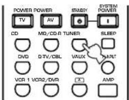
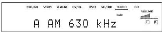
Press INPUT / (TUNER on the remote control) to select TUNER as the input source.
Front panel
or
Remote control
Press FM/AM to select the reception band. "FM" or "AM" appears on the front panel display

→
F M
or
A
Press TUNING MODE (AUTO/MAN'L MONO) so that the "AUTO" indicator lights up on the front panel display.


AUTO Lights up
If the colon (·) appears on the front panel display, press PRESET/TUNING (EDIT) to turn it off.

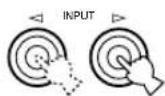
4 Press PRESET/TUNING < / > once to begin automatic tuning.
Press to tune in to a higher frequency, or press to tune in to a lower frequency.
When tuned in to a station, the "TUNED" indicator lights up and the frequency of the received station is shown on the front panel display.

- Use the manual tuning method if the tuning search does not stop at the desired station because the signal is weak.
Manual tuning
If the signal from the station you want to select is weak, you must tune in to it manually.
1 Select TUNER and the reception band following steps 1 and 2 described in "Automatic tuning" at left.
Press Tuning Mode (AUTO/MAN'L MONO) so that the "AUTO" indicator goes off from the front panel display.


AUTO
Goes off
If the colon (·) appears on the front panel display, press PRESET/TUNING (EDIT) to turn it off.
3 Press PRESET/TUNING / to tune in to the desired station manually.
Hold down the button to continue the tuning search.
Note
- Manually tuning in to an FM station will automatically change the reception mode to monaural to increase the signal quality.
Presetting stations
Automatically presetting stations (for FM stations)
You can use the automatic preset tuning feature to store FM stations. This function enables this unit to automatically tune in to FM stations with strong signals, and to store up to 40 (8 stations x 5 groups) of those stations in order. This feature enables you to easily tune in to any preset station by selecting the preset station number (see page 37).
Press FM/AM to select the FM band.


Press Tuning Mode (AUTO/MAN'L MONO) so that the "AUTO" indicator lights up on the front panel display.


3 Press and hold MEMORY (MAN'L/AUTO FM) for more than 3 seconds.
The preset number and the "MEMORY" and "AUTO" indicators flash. Then, after about 5 seconds, automatic preset tuning begins from the frequency currently displayed toward the higher frequencies.
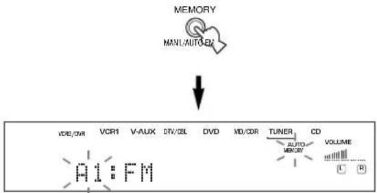
When automatic preset tuning is completed, the front panel display shows the frequency of the last preset station.
Notes
- Any stored station data existing under a preset number is cleared when you store a new station under that preset number.
- If the number of the received stations does not reach E8, automatic preset tuning has automatically stopped after searching all stations.
- Only FM stations with sufficient signal strength are stored automatically by automatic preset tuning. If the station you want to store is weak in signal strength, tune in to it manually in the monaural mode, and store it by following the procedure in "Manually presetting stations" on page 36.
Automatic preset tuning options
You can select the preset number from which this unit will store FM stations and/or begin tuning toward lower frequencies. After pressing MEMORY in step 3:
- Press A/B/C/D/E and PRESET/TUNING < / > to select the preset number under which the first station will be stored. Automatic preset tuning will stop when stations have all been stored up to E8.
- Press PRESET/TUNING (EDIT) to turn off the colon (:) and then press PRESET/TUNING < to begin tuning toward lower frequencies.
Memory back-up
The memory back-up circuit prevents the stored data from being lost even if this unit is set in the standby mode, the power cord is disconnected from the AC outlet, or the power supply is temporarily cut due to power failure. However, if the power is cut for more than one week, the preset stations may be cleared. If so, store the stations again.
Manually presetting stations
You can also store up to 40 stations (8 stations x 5 groups) manually.
1 Tune in to a station.
See page 34 for tuning instructions.
When tuned in to a station, the front panel display shows the frequency of received station.
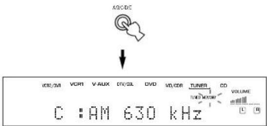
Press MEMORY (MAN'L/AUTO FM).
The "MEMORY" indicator flashes for about 5 seconds.


Flashes
3 Press A/B/C/D/E repeatedly to select a preset station group (A to E) while the "MEMORY" indicator is flashing.
The group letter appears and make sure that the colon (·) appears on the front panel display.
4 Press PRESET/TUNING to select a preset station number (1 to 8) while the "MEMORY" indicator is flashing.
Press to select a higher preset station number. Press to select a lower preset station number.
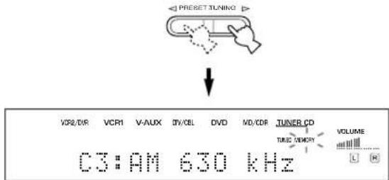
Press MEMORY (MAN'L/AUTO FM) on the front panel while the "MEMORY" indicator is flashing.
The station band and frequency appear on the front panel display with the preset group and number you have selected.

Shows the displayed station has been stored as C3.
Repeat steps 1 to 5 to store other stations.
Notes
- Any stored station data existing under a preset number is cleared when you store a new station under that preset number.
- The reception mode (stereo or monaural) is stored along with the station frequency.
Tuning in to a preset station
You can tune any desired station simply by selecting the preset station number under which it was stored.
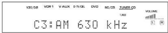
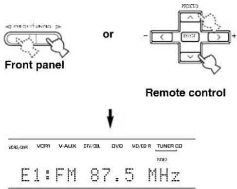
1 Press A/B/C/D/E (A/B/C/D/E on the remote control) to select the preset station group.
The preset group letter appears on the front panel display and changes each time you press A/B/C/D/E.

Front panel

Remote control
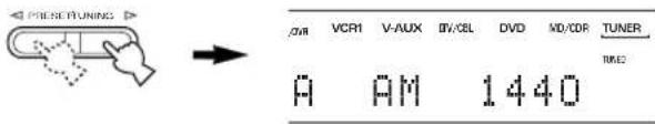
Press PRESET/TUNING / (PRESET / on the remote control) to select a preset station number (1 to 8).
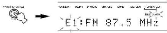
The preset group and number appear on the front panel display along with the station band, frequency and the "TUNED" indicator lights up.
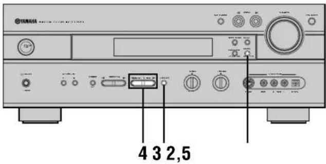
Exchanging preset stations
You can exchange the assignment of two preset stations. The example below describes the procedure for exchanging preset station "E1" with "A5".
2,41,3 1,3
1 Tune in to preset station "E1" by using the A/B/C/D/E and PRESET/TUNING /
See "Tuning in to a preset station" at left.
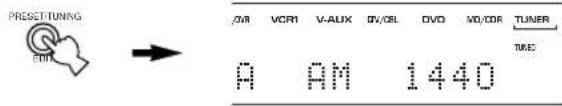
Press and hold PRESET/TUNING (EDIT) for more than 3 seconds.
"E1" and the "MEMORY" indicator flash on the front panel display.
3 Tune in to preset station "A5" by using the A/B/C/D/E and PRESET/TUNING /
"A5" and the "MEMORY" indicator flash on the front panel display.
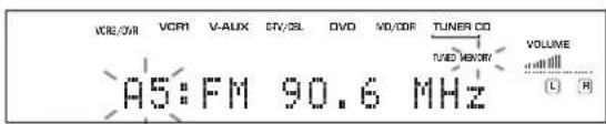
4Press PRESET/TUNING (EDIT) again.
The stations stored at the two preset assignments are exchanged.
Shows the exchange of stations has been completed.
RECEIVING RDS STATIONS RX-V630RDS
RDS (Radio Data System) is a data transmission system by FM stations in many countries.
RDS data contains various information such as PS (Program Service name), PTY (Program Type), RT (Radio Text), CT (Clock Time), EON (Enhanced Other Networks), etc. The RDS function is carried out among the network stations.
Description of RDS data
This unit can receive, PS, PTY, RT, CT, and EON data when receiving RDS broadcasting stations.
■PS (Program Service name) mode:
The name of the RDS station being received is displayed.
■PTY (Program Type) mode:
There are 15 program types to classify RDS stations.
| NEWS | News |
| AFFAIRS | Current affairs |
| INFO | General information |
| SPORT | Sports |
| EDUCATE | Education |
| DRAMA | Drama |
| CULTURE | Culture |
| SCIENCE | Science |
| VARIANT | Light entertainment |
| POP M | Pops |
| ROCK M | Rock |
| M.O.R. M | Middle-of-the-road music (easy-listening) |
| LIGHT M | Light classics |
| CLASSICS | Serious classics |
| OTHER M | Other music |
RT (Radio Text) mode:
Information about the program (such as the title of the song, name of the singer, etc.) on the RDS station being received is displayed by a maximum of 64 alphanumeric characters, including the umlaut symbol. If other characters are used for RT data, they are displayed with under-bars.
CT (Clock Time) mode:
The current time is displayed and updated every minute. If the data are accidentally cut off, "CT WAIT" may appear.
■EON (Enhanced Other Networks):
Refer to following page.
Changing the RDS mode
The four modes are available in this unit for displaying RDS data. When an RDS station is being received, PS, PTY, RT and/or CT mode indicators that correspond to the RDS data services offered by the station light up on the front panel display. Press RDS MODE/FREQ repeatedly to change the display mode among the RDS data offered by the transmitting station in the order shown below.
Notes
- When an RDS station is being received, do not press RDS MODE/FREQ until one or more RDS mode indicators light up on the front panel display. If you press the button before the indicators light up on the front panel display, the mode cannot be changed. This is because this unit has not yet received all of the RDS data on the station.
- RDS data not offered by the station cannot be selected.
- The RDS data service cannot be utilized by this unit if the received signal is not strong enough. In particular, the RT mode requires a large amount of data to be received, so it is possible that the RT mode may not be displayed even if other RDS modes (PS, PTY, etc.) are displayed.
- RDS data cannot sometimes be received under poor reception conditions. If so, press TUNING MODE so that the "AUTO" indicator goes off from the front panel display. Although the reception mode is changed to monaural by this operation, when you change the display to RDS mode, RDS data may be displayed.
- If the signal strength is weakened by external interference during the reception of an RDS station, the RDS data service may be cut off suddenly and "...WAIT" will appear on the front panel display.
PTY SEEK function
If you select the desired program type, this unit automatically searches all preset RDS stations that are broadcasting a program of the required type.
1 Press PTY SEEK MODE to set this unit in the PTY SEEK mode.
The program type of the station being received or "NEWS" flashes on the front panel display.

Press PRESET/TUNING / to select the desired program type.
The selected program type appears on the front panel display.

3 Press PTY SEEK START to begin searching all preset RDS stations.
The selected program type flashes and the "PTY HOLD" indicator lights up on the front panel display while searching for stations.
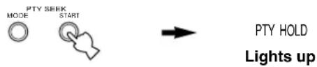
- If a station that is broadcasting a program of the required type is found, this unit stops at that station.
- If the called station is not the desired one, press PTY SEEK START again. This unit begins searching for another station that is broadcasting a program of the same type.
■To cancel this function
Press PTY SEEK MODE twice.
EON function
This function uses the EON data service on the RDS station network. If you simply select the desired program type (NEWS, INFO, AFFAIRS or SPORT), this unit automatically searches for all preset RDS stations that are scheduled to broadcast a program of the required type and switches from the station being currently received to the new station when the broadcasts starts.
Note
- This function can only be used when an RDS station that offers the EON data service is being received. When such a station is being received, the "EON" indicator lights up on the front panel display.
1 Make sure that the "EON" indicator lights up on the front panel display.
If the "EON" indicator does not light up, tune in to another RDS station so that the "EON" indicator lights up.
Press EON repeatedly to select the desired program type (NEWS, INFO, AFFAIRS or SPORT).
The selected program type name appears on the front panel display.

- If a preset RDS station of the selected program type starts broadcasting, this unit will automatically switch from the program being currently received to that program. (EON indicator flashes.)
- When broadcasting of the required program ends, the previously received station (or another program on the same station) is recalled.
■To cancel this function
Press EON repeatedly until no program type name lights up on the front panel display.
SLEEP TIMER
Use this feature to automatically set this unit in the standby mode after the amount of time you have set. The sleep timer is useful when you are going to sleep while this unit is playing or recording a source. The sleep timer also automatically turns off the external component(s) connected to AC OUTLET(S).
The sleep timer can only be set with the remote control.

- By connecting a commercially available timer to this unit, you can also set a wake-up timer. Refer to the operation instructions of the timer.
Setting the sleep timer
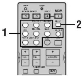
1 Select a source and start playback on the source component.
Press SLEEP repeatedly to set the amount of time. Each time you press SLEEP, the front panel display changes as shown below.

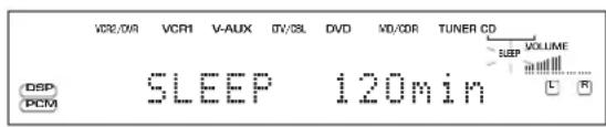
3 The "SLEEP" indicator lights up on the front panel display soon after the sleep timer has been set.
The display then returns to the previous indication.
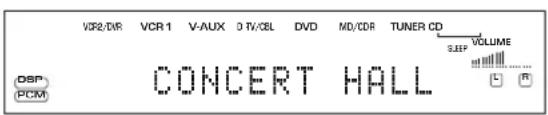
Canceling the sleep timer
Press SLEEP repeatedly until "SLEEP OFF" appears on the front panel display.
After a few seconds, "SLEEP OFF" disappears, the "SLEEP" indicator goes off and the display returns to the previous indication.

SLEEP


- The sleep timer setting can also be canceled by setting this unit in the standby mode by using STANDBY on the remote control (or STANDBY/ON on the front panel) or by disconnecting the AC power cord from the AC outlet.
RECORDING
Recording adjustments and other operations are performed from the recording components. Refer to the operation instructions for these components.
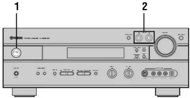
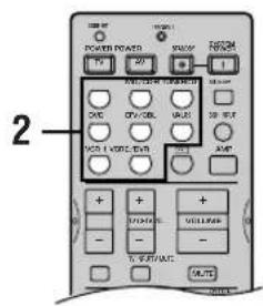
1 Turn on the power of this unit and all connected component.
2 Select the source component you want to record from.
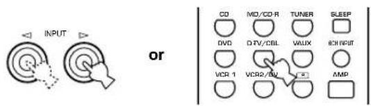
Front panel Remote control
3 Start playback (or select a broadcast station) on the source component.
4 Start recording on the recording component.
Notes
- Do a test recording before you start an actual recording.
- When this unit is set in the standby mode, you cannot record between the components connected to this unit.
- The setting of BASS, TREBLE, VOLUME, "5 L/R BALANCE" on the SET MENU and DSP programs does not effect the recorded material.
- A source connected to the 6CH INPUT jacks on this unit cannot be recorded.
- A given input source is not output to the same OUT (REC) channel. (For example, the signal input from VCR 1 IN is not output to VCR 1 OUT.)
- Check the copyright laws in your country to record from records, CDs, radio, etc. Recording of copyrighted material may infringe copyright laws.
If you playback a video source that uses scrambled or encoded signals to prevent it from being dubbed, the picture itself may be disturbed due to those signals.
■Special considerations when recording DTS software
The DTS signal is a digital bitstream. Attempting to digitally record the DTS bitstream will result in noise being recorded. Therefore, if you want to use this unit to record sources that have DTS signals recorded on them, the following considerations and adjustments need to be made.
For LDs, DVDs and CDs encoded with DTS, when your player is compatible with the DTS format, follow its operation instruction to make a setting so that the analog signal will be output from the player.
■Timer playback/recording
This unit can perform playback or recording with an external timer (not supplied). Refer to the operating instructions for the component and the timer to be used.
Notes
- Stored data, such as input source, will be reflected when playback or recording with the timer.
- If you do not want any sound output when recording with a timer, turn the volume down.
Memory back-up
The memory back-up circuit prevents the stored data (input source, volume level, set menu settings and so on) from being lost even if this unit is disconnected from the AC outlet. However, if the timer is turned off for more than one week, the stored data will be lost.
SET MENU
The SET MENU consists of 10 items including the speaker mode setting. Choose the appropriate item and adjust or select the values as necessary.

- You can adjust the items on the SET MENU while playing a source.
Items Initial settings
1 SPEAKER SET
A CENTER LRG (large)
B MAIN
LARGE
C REAR LR
LRG (large)
D REAR CT
LRG (large)
EBASS
BOTH
F MAIN Lv
Nrm (Normal)
2 LFE LEVEL SP/HP 0 dB
3 SP DLY TIME
CENTER 0 ms
REAR CNTR
3 ms
4 D. RANGE SP/HP
5 L/R BALANCE
0 dB for L/R
6 HP TONE CTRL BASS/TRBL 0 dB
7 I/O ASSIGN
A (component video input)
[A] DVD
[B] D-TV/CBL
B (optical output)
(1) MD/CDR
C (optical input)
(2) MD/CDR
(3) DVD
(4) D-TV/CBL
D (coaxial input)
(5) CD
8 INPUT MODE AUTO
9 DISPLAY SET
DIMMER
0
10 MEM.GUARD OFF
- In the descriptions for each item from the following page, the default setting is indicated in bold.
Adjusting the items on the SET MENU
■On the remote control
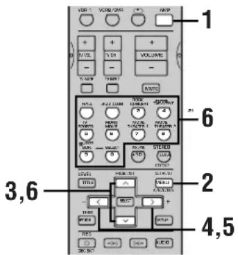
Note
- Some items require extra steps.
1 Press AMP.

2 Press SET MENU to enter the SET MENU.
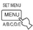
Press repeatedly to select the item you want to adjust (1 to 10).
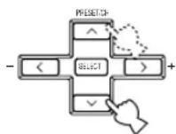

- By pressing SET MENU repeatedly, you can select items in the same order as when pressing .
4 Press / once to enter the setup mode of the selected item.
The last setting you adjusted appears on the front panel display.
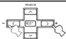
Depending on the item, press / to select a sub item.
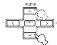
Press / repeatedly to change the setting of the item.
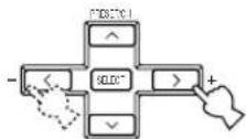
1 SPEAKER SET (speaker mode settings)
Use this feature to select suitable output modes for your speaker configuration.
6 Press repeatedly until the menu disappears or simply press one of the DSP program group buttons to exit SET MENU.
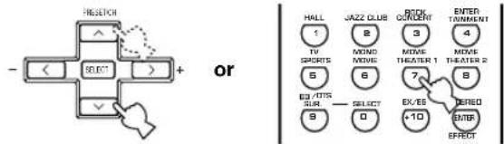
Notes
- When 96-kHz sampling digital signals are input to this unit, some items are not affected.
- When 6CH INPUT is selected as the input source, level adjustments in items 1A through 1E are not affected.
1A CENTER (center speaker mode)
By adding a center speaker to your speaker configuration, this unit can provide better dialog localization for several listeners and superior synchronization of sound and images.
DSP-AX630SE On the front panel
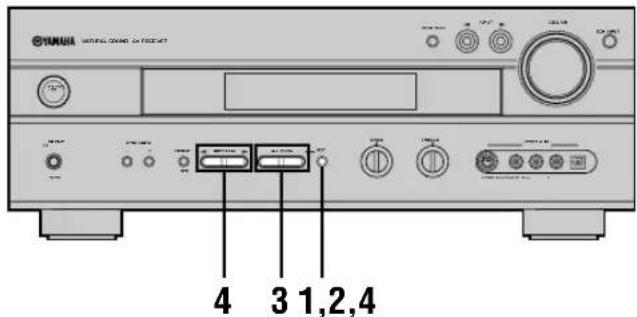
Choices: LRG (large), SML (small), NON (none)
LRG
Select this if you have a large center speaker. The entire range of the center channel signal is directed to the center speaker.
SML
Select this if you have a small center speaker. The low-frequency signals (90 Hz and below) of the center channel are directed to the speakers selected with "1E BASS".
NON
Select this if you do not have a center speaker. All of the center channel signal are directed to the main left and right speakers.
Press NEXT to enter the SET MENU.

Press NEXT repeatedly to select the item you want to adjust.

3 Press SET MENU - / + repeatedly to change the setting.
4 Press NEXT repeatedly until the menu disappears or simply press PROGRAM / to exit the SET MENU.


or
Memory back-up
The memory back-up circuit prevents the stored data from being lost even if this unit is in the standby mode. However, if the power cord is disconnected from the AC outlet, or the power supply is cut for more than one week, the stored data will be lost. If so, adjust the items again.
■1B MAIN (main speaker mode)
Choices: LARGE, SMALL
LARGE
Select this if you have large main speakers. The entire range of the main left and right channel signal is directed to the main left and right speakers.
SMALL
Select this if you have small main speakers. The low-frequency signals (90 Hz and below) of the main channel are directed to the speakers selected with "1E BASS".
■1C REAR LR (rear speaker mode)
Choices: LRG (large), SML (small), NON (none)
LRG
Select this if you have large rear left and right speakers or if a rear subwoofer is connected to the rear speakers. The entire range of the rear channel signal is directed to the rear left and right speakers.
SML
Select this if you have small rear left and right speakers. The low-frequency signals (90 Hz and below) of the rear channel are directed to the speakers selected with "1E BASS".
NON
Select this if you do not have rear speakers.

- This unit is set in the virtual CINEMA DSP mode when you select NON for "1C REAR LR". In this case, the rear center speaker will automatically be set to "NON" and the "1D REAR CT" item will be skipped.
■1D REAR CT (rear center speaker mode)
By adding a rear center speaker to your speaker configuration, this unit can provide more realistic front-to-back and transitions.
Choices: LRG (large), SML (small), NON (none)
LRG
Select this if you have a large rear center speaker. The entire range of the rear center channel signal is directed to the rear center speaker.
SML
Select this if you have a small rear center speaker. The low-frequency signals (90 Hz and below) of the rear center channel are directed to the speakers selected with "1E BASS".
NON
Select this if you do not have a rear center speaker. All of the rear center channel signal are directed to the rear left and right speakers.
■1E BASS (LFE/bass out mode)
LFE signals carry low-frequency effects when this unit decodes a Dolby Digital or DTS signal. Low-frequency signals are defined as 90Hz and below. The Low-frequency signals can be directed to both main left and right speakers, and the subwoofer (subwoofer can be used for both stereo reproduction and the DSP program).
Choices: SWFR (subwoofer), MAIN, BOTH
SWFR
Select this if you use a subwoofer. The LFE signals are directed to the subwoofer.
MAIN
Select this if you do not use a subwoofer. The LFE signals are directed to the main speakers.
BOTH
The LFE signals are directed to the subwoofer. Low-frequency signals designated to the main channels in accordance with other speaker mode settings are directed to both main speakers and a subwoofer.
Note
- When you select MAIN for "1E BASS", the low-frequency signals (90 Hz and below) of the main channel are directed to the main speakers even if you select SMALL for the main speaker mode.
■1F MAIN Lv (main level mode)
Change this setting if you cannot match the output level of the center, rear (L/R), and rear center speakers with the main speakers because of unusually high-efficiency performance from the main speakers.
Choices: Nrm (Normal), -10 dB
Nrm
Select this if you can match the output level of your effect speakers with that of your main speakers when using the test tone.
-10 dB
Select this if you cannot match the output level of your effect speakers with that of your main speakers when using the test tone.
2 LFE LEVEL
Use this feature to adjust the output level of the LFE (low-frequency effect) channel when playing back a Dolby Digital or DTS signal. The LFE signal carries the low-frequency special effect sound which is only added to certain scenes.
Control range:
SPEAKER -20 to 0 dB
HEADPHONE.....-20 to 0 dB
Initial setting: 0 dB
1 Press / to select the item to be adjusted.
Press < to adjust the LFE level.
Note
- Adjust the LFE level according to the capacity of your subwoofer or headphones.
3 SP DLY TIME (speaker delay time)
Use this feature to adjust the delay of the center and the rear center channel sounds. This feature works when there is sound output from the center speakers, with a source like Dolby Digital or DTS, etc. Ideally, the center speaker and the rear center speaker should be the same distance from the main listening position as the left and right speakers. However, in most home situations, the center speaker or the rear center speaker are placed in line with the main speakers or the rear speakers. By delaying the sound from the center speaker and the rear center speaker, the apparent distance from the center speaker and the rear center speaker to the main listening position can be adjusted to make it seem the same as the distance between the main left and right speaker, and the rear left and right speakers to the listening position. Adjusting the delay time for the center speaker is especially important for giving depth to the dialogue.
Control range:
CENTER 0 to 5 ms
REAR CNTR (center) ....... 0 to 30 ms
Initial setting:
CENTER 0 ms
REAR CNTR (center) ...... 3 ms
Press / to increase or decrease the delay of the center and the rear center channel sounds.
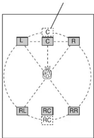
Center speaker image

- Increasing the delay by 1 ms simulates moving the speakers about 30~cm (one foot) farther away from the listening position.
4 D. RANGE (dynamic range)
Use this feature to adjust the dynamic range. This setting is effective only when this unit is decoding Dolby Digital signals.
Choices: MAX, STD (standard), MIN (minimum)
MAX
Select the "MAX" for feature films.
STD
Select the "STD" for general use.
MIN
Select the "MIN" for listening to sources at low volume levels.
5 L/R BALANCE (balance of the main left and right speakers)
Use this feature to adjust the balance of the output level from the main left and right speakers.
Control range: 20 steps for L/R
Initial setting: 0dB for L / R

Press to decrease the output level for the main left speaker. Press < for the main right speaker.
6 HP TONE CTRL (headphone tone control)
Use this feature to adjust the level of the bass and treble when you use your headphones.
Control range (dB):
BASS -6 to +3
TRBL (treble) --6 to +3
Initial setting:
BASS 0 dB
TRBL. 0 dB
7 I/O ASSIGN (input/output assignment)
It is possible to assignacks according to the component to be used if this unit's COMPONENT VIDEO input jack or DIGITAL INPUT/OUTPUT jack settings (component names for jacks) differ from that component. This makes it possible to change the jack assignment and effectively connect more components.
Once you assign, you can select that component with INPUT < / > (or the input selector buttons on the remote control).
7A CMPNT-V INPUT for COMPONENTVIDEO INPUT jacks [A] and [B]
Choices: [A] DVD, V-AUX, VCR 2/DVR, VCR 1, D-TV/CBL
[B] DVD, V-AUX, VCR 2/DVR, VCR 1, D-TV/CBL
7B OPTICAL OUT for OPTICAL OUTPUT jack (1)
Choices: (1) MD/CD-R, (DSP-AX630SE TUNER), CD, V-AUX, VCR 2/DVR, VCR 1, D-TV/CBL, DVD
7C OPTICAL IN for OPTICAL INPUT jacks (2) to (4)
Choices: (2) MD/CD-R, (DSP-AX630SE TUNER), CD, VCR 2/DVR, VCR 1, D-TV/ CBL, DVD
(3) MD/CD-R, (DSP-AX630SE TUNER), CD, VCR 2/DVR, VCR 1, D-TV/CBL, DVD
(4) MD/CD-R, (DSP-AX630SE TUNER), CD, VCR 2/DVR, VCR 1, D-TV/CBL, DVD
7D COAXIAL IN for COAXIAL INPUT jack (5)
Choices: (5) MD/CD-R, (DSP-AX630SE TUNER), CD, V-AUX, VCR 2/DVR, VCR 1, DTV/CBL, DVD
Notes
- You cannot select an item more than once for the same type of jack.
- When you connect a component to both the COAXIAL and OPTICAL jacks, priority is given to the input signals from the COAXIAL jack.
8 INPUT MODE (initial input mode)
Use this feature to designate the input mode for sources connected to the DIGITAL INPUT jacks when you turn on this unit (see page 25 for details about the input mode).
Choices: AUTO, LAST
AUTO
Select this to allow this unit to automatically detect the type of input signal and select the appropriate input mode.
LAST
Select this to set this unit to automatically select the last input mode used for the respective source.
9 DISPLAY SET
DIMMER
You can adjust the brightness of the front panel display.
Control range: -4 to 0
Initial setting: 0
10 MEM. GUARD (memory guard)
Use this feature to prevent accidental changes to settings on this unit.
Choices: ON, OFF
Select ON to protect the following features:
- All SET MENU items
- Center, rear speakers, rear center, and subwoofer levels
DSP program parameters
Notes
- When this item is set to ON, you cannot use the test tone.
- When this item is set to ON, you cannot select any other SET MENU items.
REMOTE CONTROL FEATURES
In addition to controlling this unit, the remote control can operate other A/V components made by YAMAHA and other manufacturers. To control other components, you must set up the remote control with the manufacturer codes.
Control area
Controlling this unit
The shaded areas below can be used to control this unit when the AMP mode is selected. Press AMP to select the AMP mode.
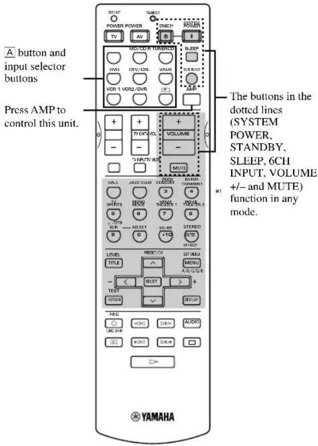
Controlling other component
The shaded areas below can be used to control other components. Each button has a different function depending on the selected components. Select the component to be controlled by pressing an input selector button.
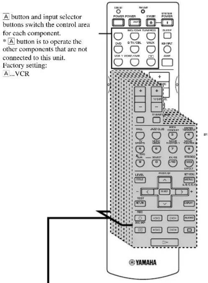
Component control area
You can control up to 9 different components. You can set up manufacturer code and program other remote control functions for each component (see page 50).
Setting the manufacturer code
You can control other components by setting a manufacturer code. Codes can be set for each of the 9 component controls.
The following table shows factory-set component (Library: component category) and the manufacturer code for each component control.
| Component control (buttons) | Component category (Library) | Manufacturer | Code |
| CD | CD | YAMAHA | 0005 |
| MD/CD-R | MD | YAMAHA | 0024 |
| TUNER | TUNER | YAMAHA | 0003 |
| DVD | DVD | YAMAHA | 0098 |
| D-TV/CBL | - | - | - |
| V-AUX | - | - | - |
| VCR 1 | - | - | - |
| VCR 2/DVR | - | - | - |
| A | - | - | - |
Press an input selector button or A to select the component you want to set up.
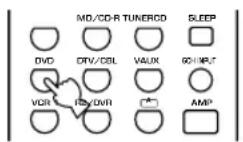
Press CODE SET using a ballpoint pen or similar object.
The TRANSMIT indicator flashes twice.


Press the numeric buttons to enter the four digit manufacturer's code for the component to be used.
Refer to "LIST OF MANUFACTURER'S CODES" at the end of this manual.
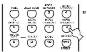
The TRANSMIT indicator flashes twice.
Notes
- If the manufacturer of your component has more than one code, try each of them until you find the correct one.
- If you wait for more than 30 seconds during step 3, the setup process is canceled. If this happens, start over from step 2.
Clearing setup manufacturer codes
■Clearing setup manufacturer code for the component control
Press an input selector button or A to select the component control for which you want to clear the manufacturer code.
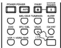
Press CODE SET by using a ballpoint pen or similar object.
The TRANSMIT indicator flashes twice.

Note
- If you do not press any button within 30 seconds after step 2, the clearing process is canceled. If this happens, start over from step 1.
3 Enter the code number "0000".
The TRANSMIT indicator flashes twice, and the manufacturer code for the selected component is cleared.

- You can clear all setup manufacturer codes at once by entering the code number "9990".
Controlling other components
You can operate other components when you have set the manufacturer code for your component. Note, however, that some buttons may not operate your component. Once you select an input source, the remote control switches to the mode for operating the component.
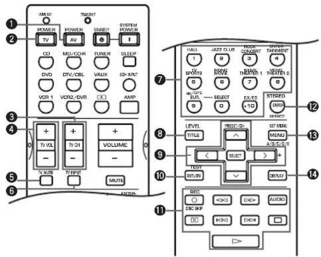
| DVD player VCR TV, digital/cable TV CD player CD/MD recorder Tuner | ||||||
| 1AV POWER * | 1Power * | 1Power * | 3VCR power * | 1Power * | 1Power * | 1Power |
| 2TV POWER * | 2TV power * | 2TV power * | 2TV power * | 2TV power * | 2TV power * | 2TV power |
| 3TV CH + * | 3TV channel up * | 3TV channel up TV channel up * | 3TV channel up * | 3TV channel up * | 3TV channel up | |
| TV CH - * | 2TV channel down | *2TV channel down | TV channel down | *2TV channel down | *2TV channel down | *2TV channel down |
| 4TV VOL + | *2TV volume up | *2TV volume up | TV volume up | *2TV volume up | *2TV volume up | *2TV volume up |
| TV VOL - | *2TV volume down | *2TV volume down | TV volume down | *2TV volume down | *2TV volume down | *2TV volume down |
| 5TV MUTE | *2TV mute | *2TV mute | TV mute | *2TV mute | *2TV mute | *2TV mute |
| 6TV INPUT * | 2TV input * | 2TV input | TV input | *2TV input | *2TV input * | 2TV input |
| 71-9, 0, +10 | Numeric buttons | Numeric buttons | Numeric buttons | Numeric buttons | Numeric buttons | Preset stations (1-8) |
| 8TITLE | Title | |||||
| 9 PRESET/CH ∩ | Up | VCR channel up | Preset up | |||
| PRESET/CH ∨ | Down | VCR channel down | Preset down | |||
| PRESENT/CH < | Left | |||||
| PRESENT/CH >Right | ||||||
| SELECT | Select | |||||
| 10RETURN Return | ||||||
| 11 REC/DISC SKIP | Disc skip | Rec | *3VCR rec | Disc skip | Rec (MD) | |
| > | Play | Play | *4 VCR play | Play | Play | |
| <>< | Search backward Search backward | *3VCR search backward | Search backward Search backward | |||
| >= | Search forward | Search forward | *3VCR search forward | Search forward Search forward | ||
| AUDIO | Audio | |||||
| || | Pause | Pause | *5VCR pause | Pause | Pause | |
| <>< | Skip backward | Skip backward | Skip backward | |||
| >= | Skip forward | Skip forward | Skip forward | |||
| □ | Stop | Stop | *6 VCR stop | Stop | Stop | |
| 12 ENTER | Title/Index | Enter | Enter | Index | Index | |
| 13 MENU | Menu | A/B/C/D/E | ||||
| 14 DISPLAY | Display | Display | Display | |||
- This button functions only when the original remote control of the component has POWER button.
*2 These buttons can operate your TV without switching the input if the manufacturer code is set in D-TV/CBL.
* These buttons can operate your VCR without switching the input to VCR if the manufacturer code is set in VCR.
You can adjust the output level of each effect speaker (center, rear left and right, rear center and subwoofer) while listening to a source.
Adjustment should be made with the remote control.
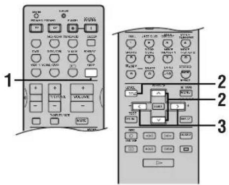
1Press AMP.

(While playing a source)
Press LEVEL repeatedly to select the speaker(s) you want to adjust.
Each time you press LEVEL, the selected speaker changes and appears on the front panel display as follows: center, rear right, rear center, rear left and subwoofer.
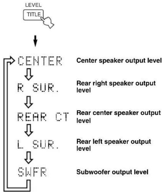

- Once you press LEVEL, you can also select the speaker(s) to be adjusted by pressing / .
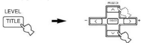
Press / to adjust the speaker output level.
- The control range for the center or rear left and right speakers is from +10 dB to -10 dB.
- The control range for the subwoofer is from 0 dB to -20dB .
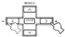
Notes
- When the speaker output modes for "1A CENTER" and "1C REAR LR" are set to NON, and "1E BASS" to MAIN, the output level of those speakers cannot be adjusted because there is no sound coming from these speakers.
- When you adjust the output level with LEVEL, the settings you made with the test tone will be changed.
- We recommend adjusting the speakers by following the steps described in "Using the test tone" on pages 21 and 22.
■For 6ch Stereo
You can adjust the volume level for each channel in 6-channel stereo mode.
Control range: 0 to 100%
CT level (Center level)
- RL level (Rear left level)
RR level (Rear right level)
- RC level (Rear center level)
1 Select 6ch Stereo.
Press / repeatedly to select the speaker(s) you want to adjust.
Press / to adjust the speaker output level.
Memory back-up
The memory back-up circuit prevents the stored data from being lost even if this unit is in the standby mode. However, if the power cord is disconnected from the AC outlet, or the power supply is cut for more than one week, the stored data will be lost. If so, set the output level again.
You can adjust the time difference between the beginning of the sound from the main speakers and the beginning of the sound effect from the rear speakers. The larger the value, the later the sound effect is generated. The delay time can be individually adjusted to all DSP programs.
The following table shows factory-set delay time.
| Program | Preset value (ms) | |
| 1. CONCERT HALL 45 | ||
| 2. JAZZ CLUB 30 | ||
| 3. ROCK CONCERT 15 | ||
| 4. DISCO 26 | ||
| GAME 36 | ||
| CONCERT VIDEO 21 | ||
| 5. TV SPORTS 10 | ||
| 6. MONO MOVIE 69 | ||
| 7. 70 mm SPECTACLE 23 | ||
| DGTL SPECTACLE 15 | ||
| DTS SPECTACLE 15 | ||
| Spectacle EX/ES | 15 | |
| 70 mm SCI-FI | 20 | |
| Sci-Fi EX/ES | 15 | |
| DGTL SCI-FI | 15 | |
| DTS SCI-FI | 15 | |
| 8. 70 mm ADVENTURE | 20 | |
| DGTL ADVENTURE | 15 | |
| DTS ADVENTURE | 15 | |
| Adventure EX/ES | 15 | |
| 70 mm GENERAL | 20 | |
| DGTL GENERAL 15 | ||
| DTS GENERAL | 15 | |
| General EX/ES | 15 | |
| 9. PRO LOGIC/NORMAL | 15 | |
| DOLBY DIGITAL/NORMAL | 5 | |
| DTS DIGITAL SUR./NORMAL | 5 | |
| Dolby D EX/DTS ES | 5 | |
| PRO LOGIC/ENHANCED | 20 | |
| DOLBY DIGITAL/ENHANCED | 5 | |
| DTS DIGITAL SUR./ENHANCED | 5 | |
| Enhanced EX/ES | 5 | |
| PRO LOGIC II Movie | 15 | |
| PRO LOGIC II Music | 5 |
Adjustment should be made with the remote control.
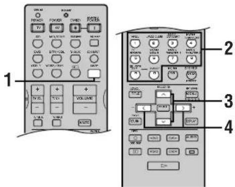
1 Press AMP.

(While playing a source)
2 Select a DSP program you want to adjust the delay time.
Press / so that "DELAY" appears on the front panel display.

4 Press / to adjust the delay time.
Notes
- Adding too much delay will cause an unnatural effect with some sources.
The sound is momentarily interrupted while adjusting the delay time.
Memory back-up
The memory back-up circuit prevents the stored data from being lost even if this unit is in the standby mode. However, if the power cord is disconnected from the AC outlet, or the power supply is cut for more than one week, the stored data will be lost. If so, adjust the delay time again.
ADJUSTING THE PARAMETER SETTINGS FOR PRO LOGIC II MUSIC
Changing parameter settings
You can adjust the values of PRO LOGIC IMusic parameters so the sound fields are recreated accurately in your listening room.
Adjustments should be made with the remote control.
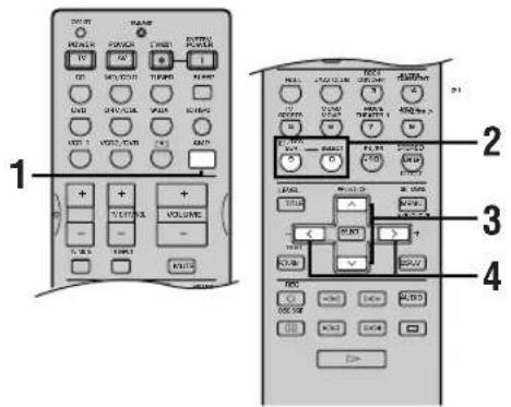
1Press AMP.

2Select PRO LOGIC Music.
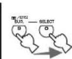
3 Press / to select the parameter.
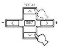
4 Press < /> to change the parameter value.
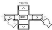
Repeat steps 3 and 4 above as necessary to change other parameters.
Note
- You cannot change parameter values when "10 MEM. GUARD" on the SET MENU is set to ON.
Memory back-up
The memory back-up circuit prevents the stored data from being lost even if this unit is set in the standby mode, the power cord is disconnected from the AC outlet, or the power supply is temporarily cut due to power failure. However, if the power is cut for more than one week, the parameter value you edited will return to the factory setting. If so, edit the parameter value again.
PRO LOGIC II Music parameter descriptions
PANorama
Function: Turning the function on extends the front stereo image to include the surround speakers for wraparound effect.
Choices: OFF/ON, initial setting is OFF.
DIMENSION
Function: Gradually adjusts the soundfield either towards the front or towards the rear.
Control range: -3 (towards the rear) to +3 (towards the front), initial setting is STD (standard).
CTWIDTH (Center width)
Function: Adjusts the center image from all three front speakers to varying degrees. The larger the value, adjusts the center image towards the main left and right speakers.
Control range: 0 (center channel sound is output only from center speaker) to 7 (center channel sound is output only from main left and right speakers), initial setting is 3.
TROUBLESHOOTING
Refer to the chart below when this unit does not function properly. If the problem you are experiencing is not listed below or if the instruction below does not help, set this unit to the standby mode, disconnect the power cord, and contact the nearest authorized YAMAHA dealer or service center.
General
| Problem | Cause | Remedy | Refer to page |
| This unit fails to turn on when STANDBY/ON (or SYSTEM POWER) is pressed, or enters in the standby mode soon after the power has been turned on. | The power cord is not connected or the plug is not completely inserted. | Firmly connect the power cord. | - |
| The IMPEDANCE SELECTOR switch on the rear panel is not fully set to either the left or right position. | Set the switch fully to the left or right position when this unit is in the standby mode. | 12 | |
| The protection circuitry has been activated. | Make sure all speaker wire connections on this unit and on all speakers are secure and that the wire for each connection does not touch anything other than its respective connection. | 10, 11 | |
| This unit has been exposed to a strong external electric shock (such as lightning and strong static electricity). | Set this unit in the standby mode, disconnect the power cord, plug it back in after 30 seconds, then start operating. | - | |
| No sound. | Incorrect input or output cable connections. | Connect the cables properly. If the problem persists, the cables may be defective. | 10 - 16 |
| An appropriate input source has not been selected. | Select an appropriate input source with INPUT <1/D> or 6CH INPUT (or the input selector buttons). | 23 | |
| The speaker connections are not secure. | Secure the connections. | 10, 11 | |
| The main speakers to be used have not been selected properly. | Select the main speakers with SPEAKERS A and/or B. | 23 | |
| The volume is turned down. | Turn up the volume. | 24 | |
| The sound is muted. | Press MUTE or any operation buttons of this unit to cancel a mute and adjust the volume. | - | |
| Digital signals which this unit cannot reproduce are being input to this unit by playing a CD-ROM, etc. | Play a source whose signals this unit can reproduce. | - | |
| The picture does not appear. | The output and input for the picture are connected to different types of video jacks. | Make connections using the same type of video jacks (S VIDEO, VIDEO (composite), or COMPONENT VIDEO) for both the input and output. | 14, 15 |
| The sound suddenly goes off. | The protection circuit has been activated because of a short circuit, etc. | Check the IMPEDANCE SELECTOR switch is set to the appropriate position and then turn this unit back on. | 12 |
| Check the speaker wires are not touching each other and then turn this unit back on. | — | ||
| The sleep timer has functioned. | Turn on the power, and play the source again. | — | |
| The sound is muted. | Press MUTE or any operation buttons of this unit to cancel a mute and adjust the volume. | — | |
| Only the speaker on one side can be heard. | Incorrect cable connections. | Connect the cables properly. If the problem persists, the cables may be defective. | 10, 11 |
| Incorrect setting of “5 L/R BALANCE” on the SET MENU. | Adjust it to the appropriate position. | 46 | |
| No sound from the effect speakers. | The sound effect is off. | Press STEREO/EFFECT to turn it on. | 28 |
| A Dolby Surround, Dolby Digital or DTS decoding DSP program is being used with material not encoded with Dolby Surround, Dolby Digital or DTS. | Select another DSP program. | 26 – 33 | |
| A 96-kHz sampling digital signal is being input to this unit. | — | ||
| No sound from the center speaker. | The output level of the center speaker is set to minimum. | Raise the level of the center speaker. | 51 |
| “I A CENTER” on the SET MENU is set to NON. | Select the appropriate mode for your center speaker. | 43 | |
| One of the Hi-Fi DSP programs (1 to 4) has been selected (except for 6ch Stereo). | Select another DSP program. | 26 – 33 | |
| The source encoded with a Dolby Digital or DTS signal does not have a center channel signal. | — | ||
| No sound from the rear speakers. | The output level of the rear speakers is set to minimum. | Raise the output level of the rear speakers. | 51 |
| A monaural source is being played with program 9. | Select another DSP program. | 26 – 33 | |
| No sound from the subwoofer. | “I E BASS” on the SET MENU is set to MAIN when a Dolby Digital or DTS signal is being played. | Select SWFR or BOTH. | 44 |
| “I E BASS” on the SET MENU is set to SWFR or MAIN when a 2-channel source is being played. | Select BOTH. | 44 | |
| The source does not contain low bass signals (90 Hz and below). | — | ||
| Poor bass reproduction. | “I E BASS” on the SET MENU is set to SWFR or BOTH and your system does not include a subwoofer. | Select MAIN. | 44 |
| The speaker mode settings (main, center, rear, or rear center) on the SET MENU does not match your speaker configuration. | Select the appropriate position for each speaker based on the size of the speakers in your configuration. | 43 – 45 |
TROUBLESHOOTING
| Problem | Cause | Remedy | Refer to page |
| No sound from the rear center speaker. | “1C REAR LR” or “1D REAR CT” on the SET MENU is set to NON. | Select LRG or SML. | 44 |
| The Dolby Digital EX decoder or the DTS-ES compatible decoder is not on. | Press the EX/ES button on the remote control to turn it on. | 28 | |
| A “humming” sound can be heard. | Incorrect cable connections. | Firmly connect the audio plugs. If the problem persists, the cables may be defective. | 10 - 16 |
| The volume level cannot be increased, or the sound is distorted. | The component connected to the OUT (REC) jacks of this unit is turned off. | Turn on the power to the component. | — |
| The sound effect cannot be recorded. | It is not possible to record the sound effect by a recording component. | — | |
| A source cannot be recorded by a digital recording component connected to the DIGITAL OUTPUT jack of this unit. | A source component is not connected to the DIGITAL INPUT jacks of this unit. | Connect the source component to the DIGITAL INPUT jacks of this unit. | — |
| The sound field parameters and some other settings on this unit cannot be changed. | “10 MEM. GUARD” in the SET MENU is set to ON. | Set “10 MEM. GUARD” in the SET MENU to OFF. | — |
| This unit does not operate properly. | The internal microcomputer has been frozen by an external electric shock (such as lightning or excessive static electricity) or by a power supply with low voltage. | Disconnect the AC power cord from the outlet and then plug it in again after about 30 seconds. | — |
| “CHECK SP WIRES” appears on the front panel display. | Speaker cables are short circuited. | Make sure all speaker cables are connected correctly. | — |
| There is noise interference from digital or high-frequency equipment, or this unit. | This unit is too close to the digital or high-frequency equipment. | Move this unit further away from such equipment. | — |
| This unit suddenly turns into the standby mode. | The internal temperature becomes too high and the overheat protection circuitry has been activated. | Wait until this unit cools down and then turn it back on. | — |
■Tuner
RX-V630RDS
| Problem | Cause | Remedy | Refer to page | |
| FM | FM stereo reception is noisy. | The characteristics of FM stereo broadcasts may cause this problem when the transmitter is too far away or the antenna input is poor. | Check the antenna connections. Try using a high-quality directional FM antenna. | 17 |
| Use the manual tuning method. | 34 | |||
| There is distortion, and clear reception cannot be obtained even with a good FM antenna. | There is multipath interference. | Adjust the antenna position to eliminate multipath interference. | — | |
| The desired station cannot be tuned in with the automatic tuning method. | The station is too weak. | Use a high-quality directional FM antenna. | 17 | |
| Use the manual tuning method. | 34 | |||
| Previously preset stations can no longer be tuned in. | This unit has been disconnected for a long period. | Re-store the stations. | 35, 36 | |
| AM | The desired station cannot be tuned in with the automatic tuning method. | The signal is weak or the antenna connections are loose. | Tighten the AM loop antenna connections and orient it for best reception. | 17 |
| Use the manual tuning method. | 34 | |||
| There are continuous crackling and hissing noises. | Noises result from lightning, fluorescent lamps, motors, thermostats and other electrical equipment. | Use an outdoor antenna and a ground wire. This will help somewhat, but it is difficult to eliminate all noise. | 17 | |
| There are buzzing and whining noises (especially in the evening). | A TV set is being used nearby. | Move this unit away from the TV. | — | |
Remote control
| Problem | Cause | Remedy | Refer to page |
| The remote control does not work nor function properly. | Wrong distance or angle. | The remote control will function within a maximum range of 6 m (20 feet) and no more than 30 degrees off-axis from the front panel. | 7 |
| Direct sunlight or lighting (from an inverter type of fluorescent lamp, etc.) is striking the remote control sensor of this unit. | Reposition this unit. | — | |
| The batteries are weak. | Replace all batteries with new ones. | 3 | |
| The manufacture code has not correctly set. | Set the code correctly. | 49 | |
| Try setting another code of the same manufacturer. | — | ||
| Even if the manufacturer code is correctly set, there are some models that do not respond to the remote control. | — |
GLOSSARY
■ Dolby Surround
Dolby Surround uses a 4 channel analog recording system to reproduce realistic and dynamic sound effects: 2 main left and right channels (stereo), a center channel for dialog (monaural), and a rear channel for special sound effects (monaural). The rear channel reproduces sound within a narrow frequency range.
Dolby Surround is widely used with nearly all video tapes and laser discs, and in many TV and cable broadcasts as well. The Dolby Pro Logic decoder built into this unit employs a digital signal processing system that automatically stabilizes the volume on each channel to enhance moving sound effects and directionality.
■ Dolby Digital
Dolby Digital is a digital surround sound system that gives you completely independent multi-channel audio. With 3 front channels (left, center, and right), and 2 rear stereo channels, Dolby Digital provides 5 full-range audio channels. With an additional channel especially for bass effects, called LFE (low frequency effect), the system has a total of 5.1 channels (LFE is counted as 0.1 channel). By using 2-channel stereo for the rear speakers, more accurate moving sound effects and surround sound environment are possible than with Dolby Surround. The wide dynamic range (from maximum to minimum volume) reproduced by the 5 full-range channels and the precise sound orientation generated using digital sound processing provide listeners with previously unheard of excitement and realism.
With this unit, any sound environment from monaural up to a 5.1-channel configuration can be freely selected for your enjoyment.
Dolby Digital EX creates 6 full-bandwidth output channels from 5.1-channel sources. This is done using a matrix decoder that derives 3 surround channels from the 2 in the original recording. For the best results, Dolby Digital EX should be used with movie sound tracks recorded with Dolby Digital Surround EX. With this additional channel, you can experience more dynamic and realistic moving sound especially with scenes with "fly-over" and "fly-around" effects.
■ Dolby Pro Logic II
Dolby Pro Logic is an improved technique used to decode vast numbers of existing Dolby Surround softwares. This new technology enables a discrete 5-channel playback with 2 main left and right channels, 1 center channel, and 2 rear left and right channels (instead of only 1 rear channel for conventional Pro Logic technology). A music mode is also available for 2-channel sources in addition to the movie mode.
DTS (Digital Theater Systems) Digital Surround
DTS digital surround was developed to replace the analog soundtracks of movies with a 6-channel digital sound track, and is now rapidly gaining popularity in movie theaters around the world. Digital Theater Systems Inc. has developed a home theater system so that you can enjoy the depth of sound and natural spatial representation of DTS digital surround in your home.
This system produces practically distortion-free 6-channel sound (technically, a left, right and center channels, 2 rear channels, plus an LFE 0.1 channel as a subwoofer, for a total of 5.1 channels).
The unit incorporates DTS-ES compatible decoder that enables 6.1-channel reproduction by adding the rear center channel to existing 5.1-channel format. (The rear center channel is created from rear left and right channels.)
LFE 0.1 channel
This channel is for the reproduction of low bass signals. The frequency range for this channel is 20Hz to 120Hz . This channel is counted as 0.1 because it only enforces a low frequency range compared to the full-range reproduced by the other 5 channels in a Dolby Digital or DTS 5.1 channel systems.
CINEMA DSP CINEMADSP
Since the Dolby Surround and DTS systems were originally designed for use in movie theaters, their effect is best felt in a theater having many speakers and designed for acoustic effects. Since home conditions, such as room size, wall material, number of speakers, and so on, can differ so widely, it's inevitable that there are differences in the sound heard as well. Based on a wealth of actually measured data, YAMAHA CINEMA DSP uses YAMAHA original sound field technology to combine Dolby Pro Logic, Dolby Digital and DTS systems to provide the visual and audio experience of movie theater in the listening room of your own home.
■ SILENT CINEMA
YAMAHA has developed a natural, realistic sound effect DSP algorithm for headphones.
Parameters for headphones have been set for each sound field so that accurate representations of all the sound field programs can be enjoyed using headphones.
■Virtual CINEMA DSP
YAMAHA has developed a virtual CINEMA DSP algorithm that allows you to enjoy DSP sound field surround effects even without any rear speakers by using virtual rear speakers.
It is even possible to enjoy virtual CINEMA DSP using a minimal 2-speaker system that does not include a center speaker.
■PCM (Linear PCM)
Linear PCM is a signal format under which an analog audio signal is digitized, recorded and transmitted without using any compression. This is used as a method of recording CDs and DVD audio. The PCM system uses a technique for sampling the size of the analog signal per very small unit of time. Standing for "pulse code modulation", the analog signal is encoded as pulses and then modulated for recording.
■Sampling frequency and number of quantized bits
When digitizing an analog audio signal, the number of times the signal is sampled per second is called the sampling frequency, while the degree of fineness when converting the sound level into a numeric value is called the number of quantized bits.
The range of rates that can be played back is determined based on the sampling rate, while the dynamic range representing the sound level difference is determined by the number of quantized bits. In principle, the higher the sampling frequency, the wider the range of frequencies that can be played back, and the higher the number of quantized bits, the more finely the sound level can be reproduced.
■S-video signal
With the S-video signal system, the video signal normally transmitted using a pin cable is separated and transmitted as the Y signal for the luminance and the C signal for the chrominance through the S-video cable. Using the SVIDEO jack eliminates video signal transmission loss and allows recording and playback of even more beautiful images.
■Component video signal
With the component video signal system, the video signal is separated into the Y signal for the luminance and the P_B / C_B and Pr / Cr signals for the chrominance. Color can be reproduced more faithfully with this system because each of these signals is independent. The component signal is also called the "color difference signal" because the luminance signal is subtracted from the color signal. A monitor with component input jacks is required in order to use the component signal for output.
SPECIFICATIONS
AUDIO SECTION
Minimum RMS Output Power for Main, Center, Rear, Rear Center 20Hz to 20kHz 0.06% THD, 8 . 75 W 1kHz 0.06% THD, 8 . 80 W
DIN Standard Output Power [Europe model] 1 kHz, 0.7% THD,4Ω 125W
Maximum Power (EIAJ) [China, Korea and General models] 1 kHz, 10% THD, 8 110 W
- Dynamic Power (IHF) 8/6/4/2 Ω .95/120/150/180 W
Damping Factor 20Hz to 20kHz,8 80 or more
Frequency Response CD to Main L/R 10 Hz to 100 kHz, -3 dB
Total Harmonic Distortion 20Hz to 20kHz 45 W,8 Main L/R .0.06%
- Signal to Noise Ratio (IHF-A Network) CD (250 mV, shorted) to Main L/R, Effect Off 100 dB
- Residual Noise (IHF-A Network)
Main L/R 150 μV or less
- Channel Separation (1 kHz/10 kHz) CD (5.1 kΩ terminated) to Main L/R 60 dB/45 dB
- Tone Control (Main L/R)
BASS Boost/Cut. ±10 dB/50 Hz
TREBLE Boost/Cut. ±10 dB/20 kHz
- Phones Output 0.34 V/560 Ω
- Input Sensitivity
CD, etc. 150 mV/47 kΩ
6CH INPUT 150 mV/47 kΩ
Output Level OUT (REC) 150 mV/1.2 kΩ OUTPUT MAIN/CENTER/REAR CENTER/ REAR (SURROUND) 2.2 V/1.2 kΩ OUTPUT SUBWOOFER 4 V/1.2 kΩ
VIDEO SECTION
Video Signal Type NTSC or PAL
Composite Video Signal Level 1 Vp-p/75Ω
S-Video Signal Level Y. 1 Vp-p/75 Ω C. 0.286 Vp-p/75 Ω
- Component Video Signal Level
Y . 1 Vp-p/75 Ω
Pb/Cb, Pr/Cr . 0.7 Vp-p/75 Ω
- Signal to Noise Ratio 50 dB
Frequency Response (MONITOR OUT) Composite, S-Video 5 Hz to 10 MHz, -3 dB Component DC to 30 MHz, -3 dB
RX-V630RDS
FM SECTION
Tuning Range [U.S.A.and Canada models] 87.5 to 107.9MHz [Other models] 87.50 to 108.00MHz
- 50 dB Quieting Sensitivity (IHF, 100% mod.)
Mono/Stereo 2.0 μV (17.3 dBf) /25 μV (39.2 dBf)
- Selectivity (400kHz) 70 dB
- Signal to Noise Ratio (IHF)
Mono/Stereo 76 dB/70 dB
Harmonic Distortion (1 kHz) Mono/Stereo . 0.2% / 0.3%
- Stereo Separation (1 kHz) 45 dB
Frequency Response 20 Hz to 15 kHz +0.5, -2 dB
AM SECTION
Tuning Range 530/531 to 1710/1611 kHz
- Usable Sensitivity 300 μV/m
GENERAL
- Power Supply
[U.S.A. and Canada models] AC 120 V/60 Hz
[Australia model] AC 240 V/50 Hz
[U.K., Europe and Singapore models] AC 230 V/50 Hz
[Korea model] AC 220 V/60 Hz
[China and General models] AC 110/120/220/240 V, 50/60 Hz
Power Consumption [U.S.A. and Canada models] 290 W/370 VA [Other models] 290 W Standby Mode approx. 0.6 W - AC Outlets [U.S.A., Canada, Europe and Singapore models] 2 (Total 100 W maximum) [China and General models] 2 (Total 50 W maximum) [U.K. and Australia models] 1 (100 W maximum)
Dimension (W× H× D) 435 x 161 x 390 mm (17" x 6-7/16" x 15-3/8")
Weight 11.5 kg (25 lbs) - Accessories . Remote control Batteries FrontVIDEO AUX jack cap RX-V630RDS 75-ohm/300-ohm antenna adapter (U.K. model)
RX-V630RDS AM loop antenna RX-V630RDS Indoor FM antenna
*Specifications are subject to change without notice.
ATTENTION: VEUILLEZ LIRE CE QUI SUIT AVANT D'UTILISER L'APPAREIL.
Corrections CINEMA-DSP 32
SYNTONISEUR RX-V630RDS 34
RECEPTION DES STATIONS RDS
RX-V630RDS 38
7 I/O ASSIGN (attribution des entrées/sorties) .... 46
9 DISPLAY SET (affichage) 47
10MEM. GUARD (secours de la mémoire) 47
FONCTIONS DU BOITIER DE
TELECOMMANDE 48

Piles (4) (AAA, R03, UM-4)
8 $1ENT (prise PHONES)
DSP-AX630SE SET MENU -/+
Corrections CINEMA-DSP
SYNTONISEUR RX-V630RDS
RéCEPTION DES STATIONS RDS RX-V630RDS
HEADPHONE.....-20 a 0 dB
Choix: [A] DVD, V-AUX, VCR 2/DVR, VCR 1, D-TV/CBL
[B] DVD, V-AUX, VCR 2/DVR, VCR 1, D-TV/CBL
9 DISPLAY SET (affichage)
■DTS (Digital Theater Systems) Digital Surround
CINEMA DSP CINEMA DSP
DIGITAL-SOUNDFELD-PROZESSOR (DSP) 29
DSP-AX630SE SET MENU -/+
These Tastes would also be used to establish the relationship between the two.
■AC OUTLETS (SWITCHED)
OFF: In this Modus工作会议, the Center-Lautsprecher has agreed to establish a new Center for the Study of the Evolution of the World's Major Species.
Hinweise
DIGITAL-SOUNDFELD-PROZESSOR (DSP)
CINEMA-DSP Programme
■EON-Modus (Enhanced Other Networks):
C REAR LR LRG (groB)
D REAR CT LRG (groB)
E BASS BOTH
F MAIN Lv Nrm (Normal)
2 LFE LEVEL SP/HP 0 dB
3 SP DLY TIME
CENTER 0 ms
REAR CNTR 3 ms
4 D. RANGE SP/HP
MAX
5 L/R BALANCE
0 dB für L/R
6 HP TONE CTRL BASS/TRBL 0 dB
7 I/O ASSIGN
A (Komponenten-Video-Eingang) [A] DVD
[B] D-TV/CBL
Wahl: SWFR (Subwoofer), MAIN, BOTH
SWFR
[B] DVD, V-AUX, VCR 2/DVR, VCR 1, D-TV/CBL
CD, V-AUX, VCR 2/DVR, VCR 1,
D-TV/CBL, DVD
CD, VCR 2/DVR, VCR 1, D-TV/
CBL, DVD
(3) MD/CD-R, (DSP-AX630SE TUNER),
CD, VCR 2/DVR, VCR 1, D-TV/
CBL, DVD
(4) MD/CD-R, (DSP-AX630SE TUNER),
CD, VCR 2/DVR, VCR 1, D-TV/
CBL, DVD
CD, V-AUX, VCR 2/DVR, VCR 1, D
TV/CBL, DVD
Hinweise
CTWIDTH (Center-Breite)
■DTS (Digital Theater Systems) Digital Surround
UPPSÄTTNING AV HÖGTALARNA 9
Högtalare 9
Hogtalarnas placering 9
JUSTERING AV HÖGTALARNAS UTNIVÄER.21
Innan du börjar 21
Att anvanda testtonen 21
GRUNDLAGGANDE ANVÄNDNING
GRUNDLAGGANDEAVSPELNING. 23
Ingangslagenochindikeringar 25
DSP-program for HiFi 29
BIOGRAF-DSP (CINEMA-DSP) 30
Ljuddesignen for CINEMA-DSP 30
CINEMA-DSP-program 32
STATIONSINSTÄLLNING [RX-V630RDS] 34
JUSTERING AVEFFEKTHOGTALARNAS LIJDNIVÄ 51
JUSTERING AV FORDROJNINGSTIDEN .... 52
JUSTERING AV
PARAMETERINSTÄLLNINGARNA FÖR

Batterier (4)
(AAA, R03, UM-4)

Lock forVIDEO AUX-uttagen pa framsidan
RX-V630RDS
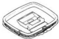
Ramantenn for AM
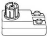
Antennadapter pa 75 ohm/ 300 ohm (Modellen for Storbritannien)
DSP-AX630SE SET MENU -/+
JusterarinstallingarpaSETMENU.
RX-V630RDS A/B/C/D/E
Väljer laget SET MENU.
14BASS
Indikatorer for processor
Indikatorer for DSP-program
Namnet pa det valda DSP-programmet tands narnagot av DSP-programmen ENTERTAINMENT, MOVIE THEATER 1, MOVIE THEATER 2 erler D/DTS SURROUND har valts.
Informationsdisplay
UPPSÄTTNING AV HÖGTALARNA
Högtalare
JUSTERING AV HÖGTALARNAS UTNIVÄER

6CH INPUT
Frontpanelen
eller

6CH INPUT
Fjarrkontrollen

ECH INPUT
Anmärkning
DSP-program for HiFi
Ljuddesignen for CINEMA-DSP
■Manuell stationsinstalling
Om signalen frän den station som du vill stalla in ar svag maste du stalla in stationen manuellt.
DVR, VCR 1, D-TV/CBL
[B]DVD,V-AUX, VCR 2/
DVR, VCR 1, D-TV/CBL
7B OPTICAL OUT for OPTICAL OUTPUT-uttaget (1)
Installningsalternativ: (1) MD/CD-R, (DSP-AX630SE
TUNER), CD, V-AUX, VCR
2/DVR, VCR 1, D-TV/CBL,
DVD
7C OPTICAL IN FOR OPTICAL INPUT-uttagen (2) till (4)
(3) MD/CD-R, (DSP-AX630SE
TUNER), CD,
VCR 2/DVR, VCR 1,
D-TV/CBL, DVD
(4) MD/CD-R, (DSP-AX630SE
TUNER), CD,
VCR 2/DVR, VCR 1,
D-TV/CBL.DVD
7D COAXIAL IN for COAXIAL INPUT-uttaget (5)
JUSTERING AV EFFEKTHÖGTALARNAS LJUDNIVÄ
■DTS (Digital Theater Systems) Digital Surround
DSP-AX630SE SET MENU -/+
AC OUTLETS (SWITCHED)
Scelta: [A] DVD, V-AUX, VCR 2/DVR, VCR 1, D-TV/CBL
[B] DVD, V-AUX, VCR 2/DVR, VCR 1, D-TV/CBL
7B OPTICAL OUT per la presa OPTICAL OUTPUT (1)
Scelta: (1) MD/CD-R, (DSP-AX630SE TUNER), CD, V-AUX, VCR 2/DVR, VCR 1, D-TV/CBL, DVD
Dolby Pro Logic is a technique that can be used to produce a program that will be used in the production of music. The program uses a computer program called Dolby Logic, which is designed to help people understand how to use computer programming. This program allows for the generation of new musical concepts and techniques. It also provides a way to learn about how to use computer programming.
■Circondamento digitale DTS (Digital Theater Systems)
Potenza dinamica (IHF) 8/6/4/2 Ω .95/120/150/180 W
Fattore attenuatione Da 20Hz a 20kHz,8 80 o piu

Pilas (4) (AAA, R03, UM-4)

Tapa de lasclerosisVIDEO AUX delanteras
RX-V630RDS
DSP-AX630SE SET MENU -/+
Establiee ajustes en SET MENU.
RX-V630RDS A/B/C/D/E
El circuito de apoyo a la memoria impide que los datos almacenados se pierdan although this is the best way to do it. It's also important to understand that there are some differences in the way of using these two concepts. For example, the use of "alimentos" instead of "categorias" may be more appropriate for the case of the same concept.
HEADPHONE.....-20 a 0 dB
Ajuste incial: 0 dB
[A] DVD, V-AUX, VCR 2/DVR, VCR 1, D-TV/CBL
[B] DVD, V-AUX, VCR 2/DVR, VCR 1, D-TV/CBL
7B OPTICAL OUT para la toma OPTICAL OUTPUT (1)
Elección:
(1) MD/CD-R, (DSP-AX630SE TUNER), CD, V-AUX, VCR 2/DVR, VCR 1, D-TV/CBL, DVD
7C OPTICAL IN para tomas OPTICAL INPUT (2) a (4)
Elección:
(2) MD/CD-R, (DSP-AX630SE TUNER), CD, VCR 2/DVR, VCR 1, D-TV/CBL, DVD
(3) MD/CD-R, (DSP-AX630SE TUNER), CD, VCR 2/DVR, VCR 1, D-TV/CBL, DVD
(4) MD/CD-R, (DSP-AX630SE TUNER), CD, VCR 2/DVR, VCR 1, D-TV/CBL, DVD
7D COAXIAL IN para la toma COAXIAL INPUT (5)
Elecction:5MD/CD-R,DSP-AX630SE TUNER), CD,V-AUX,VCR 2/DVR,VCR 1,D-TV/CBL,DVD
Notas
DSP-AX630SE SET MENU -/+
DIGITALE GELUIDSVELD BEWERKING (DSP)
CINEMA-DSP programma's
VCR 2/DVR, VCR 1, D-TV/
CBL, DVD
(3) MD/CD-R, (DSP-AX630SE
TUNER), CD, VCR 2/
DVR, VCR 1, D-TV/CBL
DVD
(4) MD/CD-R, (DSP-AX630SE
TUNER), CD, VCR 2/
DVR, VCR 1, D-TV/CBL
DVD
VCR 2/DVR, VCR 1, D-TV/
CBL, DVD
Opmerkingen
9 DISPLAY SET (installing display)
DIMMER
■DTS (Digital Theater Systems) Digital Surround
ADMIRAL 0411,0451,0911, 1021,1081
AIKO 0891
AKAI0061,0101,0231 1191,1351,1591 1641,1791,1891 1981
AKURA 1331
ALBA 1241, 1331, 2361
ALBIRAL 1971
AMSTRAD 1301, 1511
ANAM 1171
ARC EN CIEL 0571
ARCAM 0571,0761
ARISTONA 0751
ARTHUR MARTIN 0451, 164I
ASA0411,0451,0521 0781,0871,1021 1081,1421,2051 2091,2151,2551
ASTRA 1511
ATANTIC 0761
ATLANTIC 0761
ATORI 1511
AUDIOSONIC 1181,1321,1511
AUSIND 0491,1411
AUTOVOX 0091,0351,0481, 0491,0601,0781, 0951,1051,1081, 1391,1421
BAIRD 1101,1351
BANG & OLUFSEN 1081
BASIC LINE 1321, 1331
BAUER 1451
BAUR 0041,0061,0121 0131,0221,1561
BEKO 2491,2501
BLAUPUNKT 0221,0231,0241, 0251,0471,0741, 2201,2211,2221, 2231,2241,2261, 2571,2581
BRANDT 0571,0651,0731, 0901,1821
BRIONVEGA 1021, 1051, 1081
BRITANNIA 0761
BRUNs 0821,0991,1021, 1081
BSR 0391,0691,1621, 1901,1981
BUSH 0451,1241,1331 1641,1741,2131 2151
BUSH (UK) 0481, 1561, 1611
CANDLE 0791
CENTURY 1021, 1081
CGE0491,0811,0981 1401,1531,1611 1621,1981,2201 2251,2271
CITIZEN 0791
CLARIVOX 0821,0961,1971
CLATRONIC 1181,1331
CONCERTO 0791
CONDOR 0761
CONTEC 0151,1171
CONTINENTAL EDISON 0571,0651,0901
CRAIG 1171
CROSLEY 0021,0491,1021, 1081,1401,1981, 2201,2251,2271
CROWN 2541
CTC CLATRONIC 0261
CXC 1171
DAEWOO 0101,1501,1511 2611
DANSAI 0101
DECCA 0271,0581,0601, 0971,1101,1691
DECCA (UK) 0271, 0581, 0601, 1101, 1681
DEGRAAF 0451,1351
DIXI 0991
DOMEOS 0101
DORIC 1031
DUAL 0091,0601,1611, 1641,2101
DUAL-TEC 0601,1511,1621 2111
DUMONT 0261,0521,0781, 1021,1081,1981, 2121,2151
DYNATRON 0101
ELBE1551,1971,203
ELECTROTECH 1511
ELEKTRONSKA 0771
ELMAN 0261, 1621
ELTA 1511
EMERSON 0921,1021,1081, 1121,1171,1261, 1301
ERRES 0101
ETRON 1981
EUROPHON 0261,0581,0601, 0771,1091,1621, 2001
FENNER 0101, 1511
FERGUSON 0281,0371,0551, 0651,0781,0861,
0881,1131,1181 1361,1461,1971 1991,2281,2311 2341
FIDELITY 0451,0761,2281
FIDELITY (UK) 0561,0591 1931,2281
FILMNET 1141
FINLANDIA 0451,2321
FINLUX 0021, 0261, 0491, 0521, 0781, 0811, 0871, 1081, 1411, 1421, 1981, 2051, 2091, 2121, 2151, 2551
FIRST LINE 1981
FISHER 0021,0091,0141, 0511,0601,0801, 0821,0981,1021, 1081,1981,2091
FORGESTONE 2281
FORMENTI 0451,0491,0761, 1081,1451,1541, 1981
FORMENTI-PHOENIX 0021,0431,0451, 0591,1411
FORTRESS 1081
FRONTECH 0451,1181,1981
FUJITSU 1261
FUNAI0391,0691,1171 1181,126
FUTURETECH 1171
GBC 0021,0141,1321 1511,1621,1981
GEC 0451, 1101, 1281, 2321
GEC (UK) 0031, 0081, 0581, 0601, 1101, 1281, 1561
GELOSO 0021,0411,0451, 1321,1511,1621, 1981
HINARI 0071,0141,0451, 1261,1351,1511, 1641,1981,2011
HITACHI 0001,0011,0031
0081,0141,0291
0331,0341,0451
0601,0631,0701
1281, 1561, 1601,
1821,1831,1841
1861, 1871, 1881.
1891, 1941, 1981.
2051,2321,2341
HYPER 0591,0601,1511 1621
IMPERIAL 0451,0491,0811, 0981,1401,1611,
1621, 2201, 2251
2271
INGERSOL 1511
INNO HIT 0581,0601,0841
1101,1331,1371
1511,2011
INNOVATION 2591,2601,2611, 2621,2641,2651, 2661,2711,2721,
2761, 2771, 2781
INTERFUNK 0031,0041,0061
0121,0181,0451
0491, 1081, 1641
1791,1821,1981
2231
IRRADIO 0491,1321,1331
1371,1411,1511
2011
ISUKAI 1331
ITT 0031,0041,0051
0061,0071,0081
0181,0411,0451
0491, 1241, 1291,
1351, 1501, 1601,
1641, 1741, 1921,
1981,2091,2331 2431
ITT-NOKIA 0031,0041,0051
0061,0071,0081
0181,0411,0451
0491, 1241, 1291,
1351, 1501, 1601,
1641, 1741, 1921,
1981,2091,2331
2431
JVC (VICTOR) 0071, 0721, 1441
1581, 1591, 1741,
1791
KAISUI 0591,1321,1331
KAMOSONIC 0601
KARCHER 0591,0601,0841
1091, 1321, 1511
1561,2051
KAWASHO 0761
KENDO 0261
KENNEDY 0021,0351,0951
1981
KONKA 2701
KORTING 0431,1011,1021
1081, 1541
| KTV 0601, 1171 | NECKERMANN | 0451, 0601, | PRIMA | 0451 | SELECO | 0071, 0101, 0351, | |
| LENOIR 0601, 1511 | 0981, 1081, | PROFEX | 1981 | 0411, 0451, 0951, | |||
| LEYEO 1181 | 1561, 1931, | PROTECH | 0641, 1181, 1981 | 1901, 2061, 2101, | |||
| LIFETEC 2591, 2601, 2611, | 1981, 2211, | QUEILLE | 0041, 0061, 0121, | 2111 | |||
| 2621, 2641, 2651, | 2231, 2241 | 0221, 0231, 0391, | SENTRA | 1601 | |||
| 2661, 2671, 2681, | NEDIATOR | 0101 | 0491, 0521, 0601, | SHARP | 0141, 0151, 0191, | ||
| 2691, 2711, 2761, | NICAMAGIC 0761 | 0781, 1371, 1381, | 1761, 1781 | ||||
| 2771, 2781 | NIKKAI | 1101, 1331, 1641, | 1411, 1421, 1641, | SIAREM | 0021, 0261, 0581, | ||
| LOEWE OPTA 0121, 0131, 0581, | 1701, 2011 | 1681, 2051, 2091, | 0641, 1021, 1081, | ||||
| 0611, 1081 | NOBLIKO | 0261, 0491, 0591, | 2141, 2151, 2201, | 1981 | |||
| LOGIC 1691, 2281 | 0641, 1381, 1411 | 2211, 2231, 2241, | SICATEL 1971 | ||||
| LOGIK 0551, 1681, 2281 | NOGAMATIC | 0571 | 2251, 2271, 2551, | SIEMENS | 0151, 0221, 0231, | ||
| LOWEWE 0831 | NOKIA | 0031, 0041, 0051, | 2571, 2581 | 0451, 0741, 2011, | |||
| LUMA 0351, 0451, 1901 | 0061, 0071, 0081, | REDIOMARELLI | 0101, 0451, | 2201, 2211, 2221, | |||
| LUXMAN 0791 | 0181, 0411, 0451, | 0661, 0771, 1081 | 2231, 2241, 2261, | ||||
| LUXMAN STEREO TUNER | 0491, 1241, 1291, | RADIONETTE | 0031, 2051, 2091 | 2571, 2581 | |||
| 0791 | 1351, 1501, 1601, | 2291 | SILVER | ||||
| LUXOR 0001, 0061, 0181, | 1641, 1741, 1921, | RANK | 0481, 2151 | SINGER 0021, 0261, 1021, | |||
| 0341, 0421, 0451, | 1981, 2091, 2331, | 2131, 2151 | 1081 | ||||
| 0461, 0491, 0601, | 2431, 2461, 2791 | RBM | 0481 | SINUDYNE | |||
| 0671, 1351, 1371, | NORDMENDE | 0031, 0291, 0331, | 0451, 0661, 1641, | 0261, 0391, 0641, | |||
| 1561, 1601, 1911, | 0451, 0531, 0541, | 1981, 2331 | 0691, 0851, 0941, | ||||
| 1921, 1981 | 0571, 1051, 1131, | REDIFFUSION (UK) 0061, 0081, | 1021, 1081, 1241, | ||||
| LYCO 1181 | 1591, 1791, 1811, | 1031 | 1301, 1321, 1481, | ||||
| MGNADYNE 0021, 0061, 0261, | 1821, 1891, 1941, | 0071, 0101, 0351, | 1631, 1981 | ||||
| 0581, 0641, 0771, | 2631 | 0411, 0451, 0951, | SKANTIC 0451 | ||||
| 1021, 1081, 1621, | OCEANIC 0321, 1651, 1981 | 1901, 2061, 2101, | 0451, 1641, 2011 | ||||
| 1981 | OCEANIC (F) | 0031, 0061, 0321, | 2111 | SONOKO | |||
| MGNAFON 0261, 0491, 0581, | 0441, 1661 | 0991, 2511 | 0141, 0171, 1121, | ||||
| 0591, 0641, 0761, | ONCEAS 0601 | ROADSTAR | 1321, 1511 | 1681, 1691, 2751 | |||
| 1091, 2001 | ONWA | 1171 | 0151 | SOUNDESIGN | |||
| MANESTH | ORION | 0061, 0391, 0691, | SABA 0291, 0331, 0421, | 1171 | |||
| MARANTZ | 0101 | 0451, 0531, 0541, | 0071, 0101, 0351, | ||||
| MARELLI 1081 | 0851, 1211, 1241, | 0571, 0581, 0651, | 0411, 0451, 0951, | ||||
| MARK | 0101 | 0731, 0931, 1021, | 1901, 2061, 2101, | ||||
| MATSUI | 0061, 0451, 0601, | 1071, 1081, 1131, | 2111 | ||||
| 0691, 1101, 1151, | OSAKA 2011 | 1791, 1811, 1821, | SUNKAI | ||||
| 1241, 1271, 1301, | OSAKI 1101, 1331, 2011 | 1891, 1941, 2631 | 0691 | ||||
| 1511, 1561, 1681, | OSUME 0151 | SACCS 1971 | TANDBERG | ||||
| 1691 | OTTO VERSAND | 0021, 0121, | SAISHO 0451, 0601, 1161, | 1021, 1421, 1771, | |||
| MAXIMAL | 0071, 1981 | 0451, 0601, 1161, | 1791, 2081 | ||||
| MCMICHAEL | 1281 | 1241, 1301, 1511, | 1791 | ||||
| MEDION 2591, 2601, 2611, | PAEL | 0591, 1411 | TANDY | ||||
| 2621, 2641, 2651, | PANASONIC | 0031, 0201, 0211, | 0531 | ||||
| 2661, 2671, 2681, | 0451, 0701, 1311, | 0671, 1291, 1351, | 0414 | ||||
| 2691, 2711, 2721, | 1751, 1961, 2561, | 1521, 1561, 1601, | 0971, 1101, 1681, | ||||
| 2761, 2771, 2781 | 2741 | 1641, 1911, 1921, | 1691 | ||||
| MEMOREX | 1511 | PANORAMIC | 2351 | TCM | 2621, 2641, 2711, | ||
| METZ | 0231, 0741, 1001, | 0571 | 2761, 2771, 2781 | ||||
| 1041, 1081, 1481, | PATHE MARCONI | 0431, 0591, | 2761, 2771, 2781 | ||||
| 2071, 2081 | 1621, 1661, 1971 | 1411, 2001 | TECHWOOD | ||||
| MGA | 1231 | PAUSA | 1511 | TEKNIKA 1171, 1231, 1261 | |||
| MICROMAXX | 2591, 2621, 2641, | 1511 | TELE | 2761, 2771, 2781 | |||
| 2651, 2711, 2761, | PERDIO O891, 1101 | 1371, 1511, 2011 | TELEAVIA | ||||
| 2771, 2781 | PHILCO 0021, 0491, 0811, | SANYO 0491, 0541, | 2821 | ||||
| MINERVA 0221, 0231, 0491, | 0981, 1021, 1081, | 0601, 0801, 0821, | TELEFUNKEN | ||||
| 1381, 2141, 2151 | 1401, 1611, 1621, | 0981, 1021, 1101, | 0551, 0731, 1131, | ||||
| MISTRAL 2281 | 1751, 2201, 2251, | 1111, 1291, 1351, | 1471, 1591, 1791, | ||||
| MITSUBISHI | 0141, 0201, 0231, | 2271, 2451, 2471 | 1801, 1811, 1821, | ||||
| 0661, 1191, 1201, | PHILIPS 0101, 0361, 0591, | 2091, 2551 | 1991, 2161, 2171, | ||||
| 1231, 1671, 1691, | 0621, 0681, 0751, | 0681, 0751, 1281, | 2181, 2191, 2201, | ||||
| 1741 | 0761, 1021, 1081, | 2281 | 2251, 2271, 2521, | ||||
| MIVAR | 0491, 0501, 0581, | 1281, 2031, 2281 | 2631 | ||||
| 0591, 0761, 0771, | 2291, 2431, 2441, | SCHNEIDER 0021, 0071, 0091, | TELETECH | ||||
| 1371, 1431, 2031 | 2511, 2731 | 0451, 0571, 0591, | 1511 | ||||
| MTC | 0791 | PHOENIX 1081 | 0451, 0571, 1321, | 2411 | |||
| MULTITECH | 0261, 0581, 0601, | 0751, 1081 | TENSAI | 1331, 2091 | |||
| 0641, 0981, 1321, | PIONEER | 0291, 0451, 1341, | 2101, 2291 | 0601 | |||
| 1511 | 1821 | SCOTT | 1171, 1261 | THOMSON | |||
| MURPHY | 0451, 2091 | PRANDOMIPRINCE | 0411, 0451, | 0261, 0601, 0821, | 0571, 0631, 0651, | ||
| MURPHY (UK) 0081, 1031 | 0491, 0581, 1411 | 0991 | 0731, 0901, 1241 | ||||
| N.E.I. | 0101, 0961 | PRANDOMIPROMCE | 0451, | 0641, 0691, 1081, | 1571, 1591, 1791, | ||
| NAD | 1341 | 0491, 0581 | 1301, 1481, 1981 | 1811, 1821, 1891, | |||
| NEC | 0141, 1711, 1721, | THORN 0741, 0861, 2091, | |||||
| 1731 |
THORN-FERGUSON 0281,0371, 0551,0651,0781, 0861,0881,1131, 1181,1361,1461
1971, 1991, 2281
TMK 0141, 0791, 1471
TOSHIBA 0141,0381,0481, 1221,1271,1701, 1741,1851,2151, 2801,2811
TRANS CONTINENS 0451
TRISTAR2281
TRIUMPH 0481,0581,2121
UHER0431,0451,0481, 0491,0511,1311, 1541
ULTRAVOX 0021,0261,0591, 1021,1081,1981
UNIVERSUM 1181,2051
UNIVOX 1971
VEGAVOX 0811
VEXA 0101, 1511
VIDEOTON 2481
VORTEC 0101,0651
VOXSON 0411,0451,0491, 1021,1081
WALTHAM 0451
WATSON 0431,2201,2241
WATT RADIO 0021,0061,0261, 0591,0641,0761, 1091,1971,1981, 2001
WEGA 0141,1081,1981
WEGA COLOR 1021
WELTBlick 0101
WESTON 1621
WHITE WESTINGHOUSE 0101,0261,0431, 0591,0761,1401, 1541
YOKO 0601,1511
ZANUSSI 0071,0101,0351, 0411,0451,0951, 1901,2061,2101, 2111
ZOPPAS 0451
CABLE TV
CABLETIME 1446,1456,1476
CLYDE CABLEVISION 1426
FILMNET 1396, 1436
FRANCE TELECOM 1386
GEC 1426
JERROLD 1416
MOVIE TIME 1466
NSC 1466
PHILIPS 1386
PIONEER 0006
SAMSUNG 1496
SCIENTIFIC ATLANTA 1486,1506
STARCOM 1416
STS 1466
TANDBERG 1366
TELE 1436
TELE +1 1436
TELESERVICE 1406, 1476
TUDI 1376
UNITED CABLE 1416
ZENITH 1406
SATELLITE TUNER
AKAI 1276
ALBA 0826,1276
AMSTRAD 0166,0796,1016, 1026,1296
ANKARO 0476
AST 0406
ASTRA 0126
BARCOM 0476
BLAUPUNKT 0966
BMC SATELLITE 0106
BRITISH TELECOM 1276
BUSH 0826
BUSH (UK) 0956
CAMBRIDGE 0196,1276
CANAL PLUS (FRANCE) 1536
CHAPARRAL 0016,0696,1006
COLUMBUS 0616
CONNEXIONS 0306,0426
DISCUS ELIPSE 0856,0866
DISKXPRESS 0426,0476
DRAKE 1516
ECHOSTAR 0226,0236,0606, 0626,0666,0926, 0996,1046,1056, 1066,1106
ELTA 1286
ELTA SAT 0146
EURODEC 1226, 1236, 1246
FERGUSON 0046,0176,0186, 0296,0846,0956, 1306
FINLUX 0976
FRACARRO 0026,0536,0776
FUBA 0476,0616,0636. 1056
GIUCAR RECORD 0206,0336
GRUNDIG 0176,0946,0956, 0966
HIGH PERFORMANCE 0916
HIRSCHMANN 0756,0966
HITACHI 0446,0516,0706, 0946
ICX INTERNATIONAL 0886
ITT 0066,0126,0176, 0446,1156
ITT/NOKIA 0066,0126.0176, 0446,1156
JEEMON 0146
JERROLD 0846, 0986
JOHANSSON 0246
JVC 1276
KATHREIN 0116,0266,0276 0366
KOSMOS 0266
KYOSTAR 1036,1086
LENG 0246
LIFESAT 1326,1346,1356
LUXOR 0126,0136,0446, 0466,0506,1156
MACAB 0356
MASPRO 0016,0116,0256, 0956
MEDION 1326,1346
METZ 0966
MICROMAXX 1326, 1346
MITSUBISHI 0966
MORGANS 0596
MURATTO 0406
NEC 0286, 0316, 0766, 0786, 0836
NETWORK 0046
NIKKO 1136,1146
NOKIA 0066,0126,0176, 0446,1156,1166, 1336
NORSAT 0786
OTTO VERSAND
PACE 0046,0176,0296 0936,0956,1306 1566,1576
PACE MSS 0946
PACE SKY DIGITAL BOX (UK) 1526
PALCOM0616,0686,0706
PALSAT 0396
PALTEC 0706
PANASONIC 0806,1306
PANSAT 1076
PHILIPS 0326,0346,0476, 0956,1126,1186, 1196,1206,1216, 1306,1316
PROSAT 1176
PTT TELECOM 0306,0896
QUELLE 0966
RADIX 1056
REDIFFUSION 0316,0786
RFT 1186,1196,1206, 1216
SAGEM 1256,1546
SAKURA 0566,0816
SALORA 0066,0126,0136, 0446,0456,0486, 0496,0576
SAMSUNG 0746,0756
SAT 0406
SATCOM 0896
SATECO 0646
SECTOR 1266
SEDEA 1096
SENTRA 0416
SIEMENS 0896,0966
SINTRACK 0906
SKYLAB 0476
SKYSCAN 0876
SONY0736,0946
STELLA 0306
STRONG 0156,0396,1036, 1086
STV 0636
TANDBERG 1116
TANDY 0916
TANTEC 0616
TATUNG 0516,0546
TECHNISAT 0086,0096,0526, 0556,1056
TELECOM 0306
TELEMAX 0586
THORN-FERGUSON 0046,0076, 0176,0186.0956
TOSHIBA 0946
TPS (FRANCE) 1546
TRIAD 0406
UNIDEN 0036,0216,0676, 0716,0726
US ELECTRONICS
VORTEC 0756,1036,1076
VTECH 0436
WINERSAT 0246
WISI 0056,0356,0376, 0386,0406,0656, 1056,1156
WOLSEY 0916
XCOM MULTIMEDIA 1556
XSAT (FRANCE) 1556
ZEHNDER 0266,0406
ZENDER 0406
VCR
AIWA 0042,0352,0432
AKAI 0042,0422,0492
0582,0612,0642
0652,0762,0912
ALBA 0002,0112,0282
0332,0342,0972
AMSTRAD 0322,0432,0452
ANITECH 0002
ANTTsch 1002
ASA 0012,0052
AUDIOSONIC 0002
BAIRD 0042,0282,0492
BANG & OLUFSEN 0042
BAUR 0052, 0062, 0812
BLAUPUNKT 0062,0092,0252, 0462,0672,0992
BRIONVEGA 0032
BUSH 0002,0282,0332 0342,0512,0972
BUSH (UK) 0812
CAPEHART 0112
CGE 0042,0432,0762
CRAIG 0072,0482
CROWN 0112,0282,0622
DAEWOO 0112,0282,0622
DANSAI 0012
DAYTRON 0112
DECCA 0042,0052,0432, 0942
DECCA (UK) 0052
DEGRAAF 0052,0132,0432 0532,0602
DIXI 0442
DUAL 0042,0632
DUMONT 0052,0432,0532
DYNATECH 0432
DYNATRON 0012
ELBE 0122
ELIN 0072
EMERSON 0012, 0162, 0202
0432,0512,0522
ERRES 0012
FERGUSON 0042,0712,0722, 0852,0902,1012 1022,1082
FIDELITY 0432
FINLANDIA 0052,0532
FINLUX 0012,0042,0052
0082,0262,0382
0432,0462,0492
0532,0572,0602
0912
FIRST LINE 0002, 0912
FISHER 0162,0482,0532 0542,0572,0592
FORMENTI-PHOENTX
0012,0052
FRONTECH 0112
FUNAI 0432
GBC
GEC (UK) 0022,0052
GELOSO 0002
ITT 0022,0032,0042, 0072,0292,0492, 0532,0572,0762
ITT-NOKIA 0022,0032,0042, 0072,0292,0492, 0532,0572,0762
JENSEN 0042
JVC (VICTOR) 0042, 0102, 0142, 0272, 0742, 0762, 0782, 0902
KARCHER 0052,0072,0812
KENDO 0492
KENWOOD 0042,0142,0572
LIFETEC 1142,1162,1172
LLOYD 0432
LOEWE OPTA 0052,0092,0152
LOGIK 0002,0072,0442
LUMA 0162
LUXOR 0492,0572,0812
M ELECTRONIC 0432
MGNADYNE 0052
MAGNASONIC 0572
MANESTH 0012
MARANTZ 0012,0052.0092, 0122,0502
MARK 0012
MARTA 0012
MATSUI 0012, 0442, 0512, 0522, 0812, 0972
MEDION 1142,1162,1172
MEMOREX 0012,0132,0432, 0482,0532,0572
METZ 0062,0092,0932
MGA 0912
MICROMAXX 1142, 1162, 1172
MINERVA 0062,0092,0252
MINOLTA 0172,0602
MITSUBISHI 0052,0062,0142
0912, 0922
0072,0432
MULTTTECH 0002,0052,0062 0282,0432
MURPHY 0432
N.E.I. 0012,0052
NATIONAL 0462
NEC 0042,0122,0142
NECKERMANN 0032, 0042
0052.0072
0092.0202
0522.0572
0762.0812
NIKKAI 0112
NOBLIKO 0092
NOKIA 0022,0032,0042, 0072,0292,0492, 0532,0572,0762, 1152
NORDMENDE 0042,0102,0142, 0192,0222,0242
0392,0402,0632
0732,0742,0762
0782,0792,0832
0842,0872
OLYMPUS 0462
OPTONICA 0132,0502
ORION 0162,0202,0312, 0442,0512,0522
0982
OSAKA 0432
OSAKI 0002,0012,0432
OTTO VERSAND 0052,0062, 0812
PANASONIC 0022,0212,0462, 0672,0992,1092, 1102,1182
PENTAX 0172,0602
PERDIO 0432
PHILCO 1062
PHILIPS 0052,0082,0092 0152,0182,0362 0372,0382,0472 0502,1072
PHONOLA 0052,0152
PILOT 0012
PIONEER 0052,0142,0372, 0472
PORTLAND 0112
PROLINE 0432
PYE 0052,0152
QUARTZ 0572
QUELLE 0012,0032,0042
0052,0062,0072
0092,0202,0462 0522,0942
RADIONETTE 0022
REALISTIC 0012,0072,0132, 0432,0482,0502, 0532,0572
RET 1072
REX 0042,0742,0782
RICOH 0952
SABA 0042,0142,0192
0222, 0242, 0392
0632,0732,0742
0762,0772,0782
0792,0872
SAISHO 0162,0202,0292, 0442,0512,0522, 0972
SALORA 0192,0572,0812, 0822,0912
SAMSUNG 0052, 0072, 0622
0652,1192
SANSUI 0042,
SANYO 0482,0532,0562, 0572
SBR 0052,0152,0182
SCHAUBLORENZ 0022,0042
SCHNEIDER 0002,0012,0052 0072,0432
SEG 0002,0072 SEI-SINUDYNE 0442
SELECO 0042
SENTRA 0112
SHARP 0132,0502,0702
SHINTOM 0002
SIEMENS 0062,0092,0252, 0572
SINUDYNE 0052,0382,0442, 0932
SONOKO 0282
SONY 0432,0552,0682, 0692,0942,0952, 0962,1122,1132
STS 0602
SUNKAI 0512
SUNSTAR 0432
SYLVANIA 0432,0912
SYMPHONIC 0432,0912
TANDBERG 0062,0162,0522, 0932
TASHIKO 0132,0432
TATUNG 0042,0052,0432, 0922
TCM 1142,1162,1172
TEAC 0042,0432
TECHNICS 0462
TEKNIKA 0012, 0432
TELEFUNKEN 0042,0192,0632, 0732,0742,0762, 0782,0882,0892
TEMPEST 1032, 1042, 1052
TENOSAL 0002
THOMSON 0042,0102,0142, 0192,0402,06 0762
THORN 0042,0902
THORN-FERGUSON 0042, 0222
0302, 0712
0722, 0742
0762,0852
0862,0872.
0902
TMK 0522
TONSAI 0002
TOSHIBA 0042,0622,0912
TOTEVISION 0012,0072
TRIUMPH 0922
UHER 0042,0072
ULTRAVOX 0032
UNITECH 0072
VECTOR RESEARCH
0122
VIDEO 1162,1172
WELTBICK 0012
WHITE WESTINGHOUSE 0032
XENON 0162
YAMAHA 0042,1202
YOKO 0012,0062,0072
DVD PLAYER
AKAI 0058
DENON 0188
HITACHI 0198
JVC 0088,0178
KENWOOD 0148
MAGNAVOX 0128
MITSUBISHI 0138
ONKYO 0068,0128
PANASONIC 0028
PHILIPS 0098,0128
PIONEER 0108,0118
PROSCAN 0158
RCA 0158
SAMSUNG 0078
SHARP
SONY 0018
TECHNICS 0028
THOMSON 0168
TOSHIBA 0048,0128
YAMAHA 0008,0028,0098
ZENITH 0128
LD PLAYER
AIWA 0137
FUNAI 0137
HITACHI 0047
MAGNAVOX 0077
PANASONIC 0027
PIONEER 0037
RCA 0067
REALISTIC 0137
SAMSUNG 0017, 0087
SONY 0057,0097,0107 0117
VICTOR 0127
YAMAHA 0007
CD PLAYER
ACCUPHASE 0315
ADC 0865
ADCOM 0785,1015
AKAI 0115,0125,0725 0735,0745,0935 1155
ARCAM 1875
ARCAM-ROTEL
AUDIO-TECHNICA 0835
AUDIOSONIC 0155
AIWA 1105,1235,1245 1765,1915,1935
BSR 0875
CALIFORNIA AUDIO LAB
1075
CARRERA 0555,0875
CARVER 0825,1415
CYRUS-ROTEL 0205
DENON 0045,0955,1045
1595, 1795, 1805
DUAL 1005
ELIN 0185
EMERSON 1015, 1285, 1675
FISHER 0105,0595,0605
0825,1165,1175
GENEXXA 0525,0825,0855
0875.0995.1265.
-
- 1355.
1485,1575,1675
1715,1825
GOLDSTAR 0555,1185,1195 1585
GRUNDIG 0175
HARMAN KARDON 0325,0495
0565,1135,1145.
1155
HITACHI 0065,0585,0685
0945, 1005, 1015
1225.1545
INNOVATION 1995,2005,2015
ITT-NOKIA 0185
JVC (VICTOR) 0385, 0395, 0455
0575,0585
KARCHER 0485
KENWOOD 0025,0055,0145
0215,0595,0675
0695,0705,0715
0925,1355,1485
1575, 1675, 1715
1825
KORTING 0175
LIFETEC 2015
LIGHT CONTROL 1155, 1645
1655, 1665
LINN 0165,1875
LUXMAN 0265,0275,0795
0805,1295,1305
1555, 1925
LUXOR 0185, 1895, 1905
MAGNAVOX 1865, 1875
MARANTZ 0165,0175,0545, 0665,1275,1335, 1405,1505,1875, 1955


