HMDA420 - Monitor SONY - Free user manual and instructions
Find the device manual for free HMDA420 SONY in PDF.
User questions about HMDA420 SONY
0 question about this device. Answer the ones you know or ask your own.
Ask a new question about this device
Download the instructions for your Monitor in PDF format for free! Find your manual HMDA420 - SONY and take your electronic device back in hand. On this page are published all the documents necessary for the use of your device. HMDA420 by SONY.
USER MANUAL HMDA420 SONY
Trinitron ^® Color Computer Display
Operating Instructions ____ GB
Mode d'emploi FR
The model and serial numbers are located at the rear of the unit. Record these numbers in the spaces provided below. Refer to them whenever you call upon your dealer regarding this product. Model No. ____ Serial No. ____
WARNING
To prevent fire or shock hazard, do not expose the unit to rain or moisture.
Dangerously high voltages are present inside the unit. Do not open the cabinet. Refer servicing to qualified personnel only.
INFORMATION
This product complies with Swedish National Council for Metrology (MPR) standards issued in December 1990 (MPR II) for very low frequency (VLF) and extremely low frequency (ELF).
INFORMATION
As an ENERGY STAR Partner, Sony Corporation has determined that this product meets the ENERGY STAR guidelines for energy efficiency.
Table of Contents
Precautions....4
Identifying parts and controls 5
Setup....6
Step 1: Connect your monitor to your computer ..... 6
Step 2: Connect the power cord....6
Step 3: Turn on the monitor and computer ..... 6
Connecting Universal Serial Bus (USB) compliant peripherals .... 7
Selecting the on-screen menu language
(LANGUAGE/INFORMATION) 7
Customizing Your Monitor....8
Navigating the menu....8
Adjusting the brightness and contrast. 9
Adjusting the picture quality (PICTURE EFFECT) 9
Adjusting the centering of the picture (CENTER) ..... 10
Adjusting the size of the picture (SIZE) 10
Enlarging or reducing the picture (ZOOM) 10
Adjusting the shape of the picture (GEOMETRY) 10
Adjusting the convergence (CONVERGENCE) 10
Adjusting the color of the picture (COLOR) 11
Additional settings (SCREEN) 11
Resetting the adjustments (RESET)....11
Technical Features ....12
Preset and user modes....12
Power saving function....12
Troubleshooting....12
If thin lines appear on your screen (damper wires)....12
On-screen messages 12
Trouble symptoms and remedies 13
Self-diagnosis function 15
Specifications....15
Appendix....i
Preset mode timing table ....i
- Trinitron ^1 is a registered trademark of Sony Corporation.
• Macintosh is a trademark licensed to Apple Computer, Inc., registered in the U.S.A. and other countries.
- Windows ^-1 and MS-DOS are registered trademarks of Microsoft Corporation in the United States and other countries.
- IBM PC/AT and VGA are registered trademarks of IBM Corporation of the U.S.A.
- VESA and DDC ^-1 are trademarks of the Video Electronics Standard Association.
• ENERGY STAR is a U.S. registered mark.
- All other product names mentioned herein may be the trademarks or registered trademarks of their respective companies.
- Furthermore, “[]” and “[]” are not mentioned in each case in this manual.
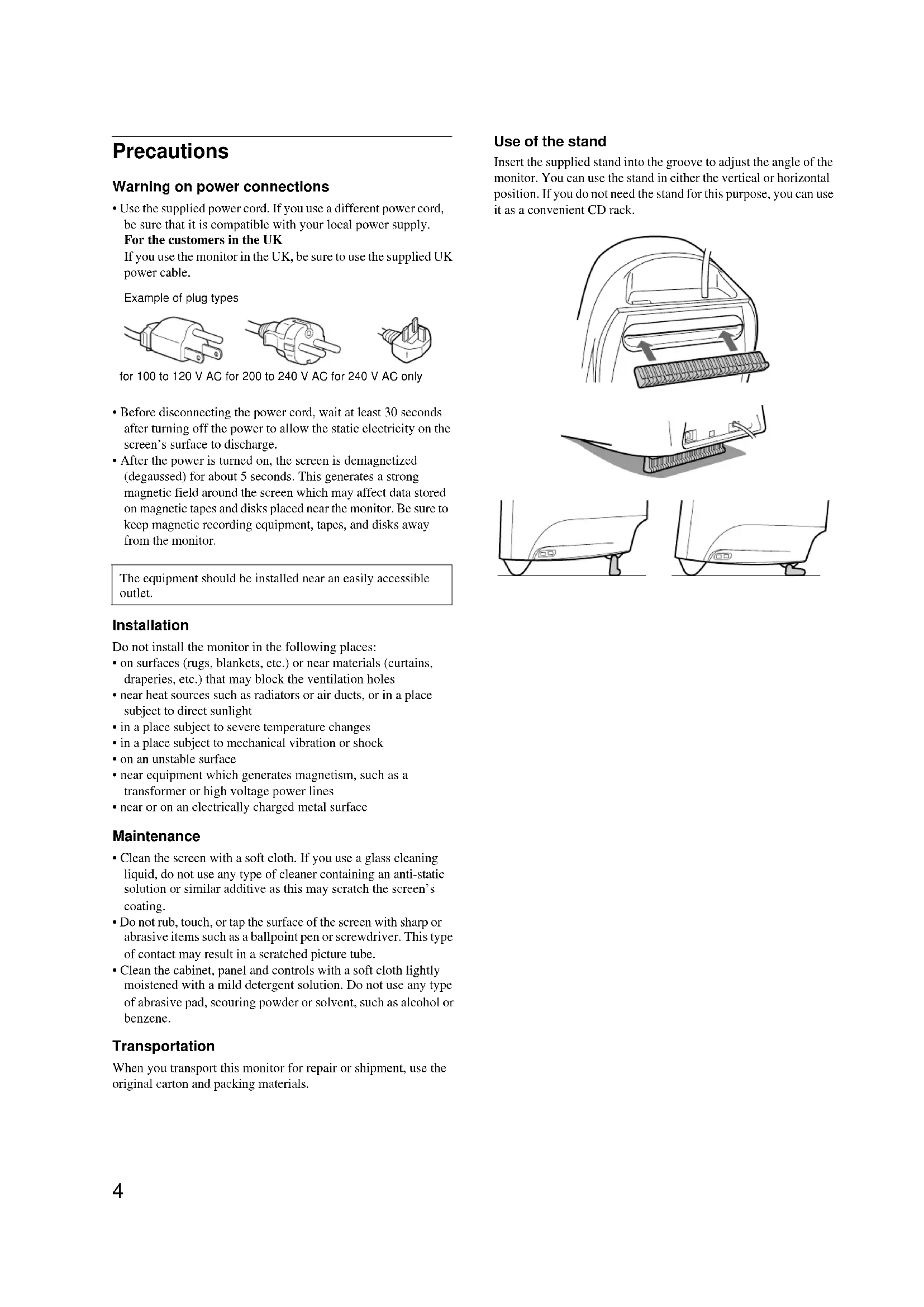
Precautions
Warning on power connections
- Use the supplied power cord. If you use a different power cord, be sure that it is compatible with your local power supply.
For the customers in the UK
If you use the monitor in the UK, be sure to use the supplied UK power cable.
Example of plug types
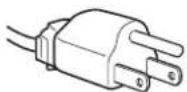
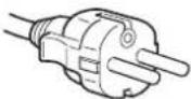
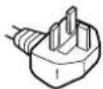
for 100 to 120 V AC for 200 to 240 V AC for 240 V AC only
- Before disconnecting the power cord, wait at least 30 seconds after turning off the power to allow the static electricity on the screen's surface to discharge.
• After the power is turned on, the screen is demagnetized (degaussed) for about 5 seconds. This generates a strong magnetic field around the screen which may affect data stored on magnetic tapes and disks placed near the monitor. Be sure to keep magnetic recording equipment, tapes, and disks away from the monitor.
The equipment should be installed near an easily accessible outlet.
Installation
Do not install the monitor in the following places:
- on surfaces (rugs, blankets, etc.) or near materials (curtains, draperies, etc.) that may block the ventilation holes
- near heat sources such as radiators or air ducts, or in a place subject to direct sunlight
• in a place subject to severe temperature changes
• in a place subject to mechanical vibration or shock
• on an unstable surface - near equipment which generates magnetism, such as a transformer or high voltage power lines
- near or on an electrically charged metal surface
Maintenance
- Clean the screen with a soft cloth. If you use a glass cleaning liquid, do not use any type of cleaner containing an anti-static solution or similar additive as this may scratch the screen's coating.
- Do not rub, touch, or tap the surface of the screen with sharp or abrasive items such as a ballpoint pen or screwdriver. This type of contact may result in a scratched picture tube.
- Clean the cabinet, panel and controls with a soft cloth lightly moistened with a mild detergent solution. Do not use any type of abrasive pad, scouring powder or solvent, such as alcohol or benzene.
Transportation
When you transport this monitor for repair or shipment, use the original carton and packing materials.
Use of the stand
Insert the supplied stand into the groove to adjust the angle of the monitor. You can use the stand in either the vertical or horizontal position. If you do not need the stand for this purpose, you can use it as a convenient CD rack.

natural_image
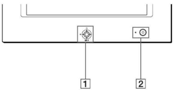
Technical line drawings of car interior components including dashboard, brush, and seat cover (no text or symbols)Identifying parts and controls
See the pages in parentheses for further details.
text_image
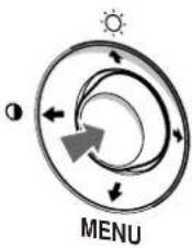
Diagram showing two labeled components (1 and 2) connected by a line with circular symbols, likely representing a mechanical or electrical component.1 Control button (page 9)
The control button is used to display the menu and make adjustments to the monitor, including brightness and contrast adjustments.
② ① (power) switch and indicator (pages 6, 12, 15)
This button turns the monitor on and off. The power indicator lights up in green when the monitor is turned on, and either flashes in green and orange, or lights up in orange when the monitor is in power saving mode.
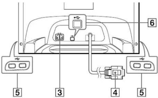
③ AC IN connector (page 6)
This connector provides AC power to the monitor.
RearFront
text_image
6 5 3 4 54 Video input connector (HD15) (page 6)
This connector inputs RGB video signals (0.700 Vp-p, positive) and sync signals.
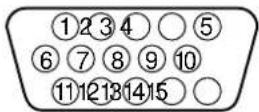
Pin No. Signal
| 1 | Red | |||
| 2 Green | ||||
| 3 | B | l | u | e |
| 4 ID (Ground) | ||||
| 5 DDC Ground* | ||||
| 6 Red Ground | ||||
| 7 Green Ground | ||||
| 8 Blue Ground | ||||
| 9 DDC + 5V* | ||||
| 10 Ground | ||||
| 11 ID (Ground) | ||||
| 12 Bi-Directional Data (SDA)* | ||||
| 13 H. Sync | ||||
| 14 V. Sync | ||||
| 15 Data Clock (SCL)* | ||||
* DDC (Display Data Channel) is a standard of VESA.
⑤USB (universal serial bus) downstream connectors (page 7)
Use these connectors to link USB peripheral devices to the monitor.
6 USB (universal serial bus) upstream connector (page 7)
Use this connector to link the monitor to a USB compliant computer.
Setup
Before using your monitor, check that the following accessories are included in your carton:
- Power cord (1)
- USB cable (1)
- Monitor stand (1)
- Warranty card (1)
- Notes on cleaning the screen's surface (1)
• This instruction manual (1)
Step 1: Connect your monitor to your computer
Turn off the monitor and computer before connecting.
Note
Do not touch the pins of the video cable connector as this might bend the pins.
■ Connecting to an IBM PC/AT or compatible computer
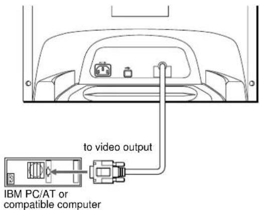
text_image
to video output IBM PC/AT or compatible computer■ Connecting to a Macintosh or compatible computer
You will need a Macintosh adapter (not supplied).
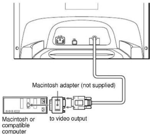
text_image
Macintosh adapter (not supplied) Macintosh or compatible computer to video outputStep 2: Connect the power cord
With the monitor and computer switched off, first connect the power cord to the monitor, then connect it to a power outlet.
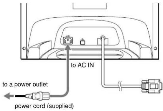
text_image
to a power outlet power cord (supplied) to AC INStep 3: Turn on the monitor and computer
First turn on the monitor, then turn on the computer.
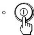
The installation of your monitor is complete.
If necessary, use the monitor's controls to adjust the picture.
If no picture appears on your screen
- Check that the monitor is correctly connected to the computer.
- If NO INPUT SIGNAL appears on the screen, confirm that your computer's graphic board is completely seated in the correct bus slot.
- If you are replacing an old monitor with this model and OUT OF SCAN RANGE appears on the screen, reconnect the old monitor. Then adjust the computer's graphic board so that the horizontal frequency is between 30 – 96 kHz, and the vertical frequency is between 48 – 120 Hz.
For more information about the on-screen messages, see “Trouble symptoms and remedies” on page 13.
Setup on various OS (Operating System)
This monitor complies with the "DDC" Plug & Play standard and automatically detects all the monitor's information. No specific driver needs to be installed to the computer.
If you connect the monitor to your PC, and then boot your PC for the first time, the setup Wizard may be displayed on the screen. Click on "Next" several times according to the instructions from the Wizard until the Plug & Play Monitor is automatically selected so that you can use this monitor.
For customers using Windows NT4.0
Monitor setup in Windows NT4.0 does not use the display driver. Refer to the Windows NT4.0 instruction manual for further details on adjusting the resolution, refresh rate, and number of colors.
Connecting Universal Serial Bus (USB) compliant peripherals
Your monitor has one upstream USB connector (on the rear panel) and four downstream USB connectors (two on both the left and right sides). They provide a fast and easy way to connect USB compliant peripheral devices (such as keyboards, mice, printers and scanners) to your computer using a standardized USB cable. To use your monitor as a hub for your peripheral devices, connect the USBs as illustrated below.
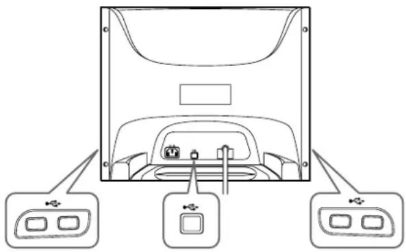
natural_image
Diagram of a computer monitor rear view with three labeled ports (no text or symbols present)to USB compliant peripheral devices
to a USB compliant computer
to USB compliant peripheral devices
1 Turn on the monitor and computer.
2 Connect your computer to the square upstream connector using the supplied USB cable.
For customers using Windows
If a message appears on your screen, follow the on-screen instructions and select Generic USB Hub as the default setting.
3 Connect your USB compliant peripheral devices to the rectangular downstream •USB connectors.
Notes
- Not all computers and/or operating systems support USB configurations. Check your computer's instruction manual to see if you can connect USB devices.
- In most cases, USB driver software needs to be installed on the host computer. Refer to the peripheral device's instruction manual for further details.
- The monitor functions as a USB hub as long as the monitor is either "on" or in power saving mode.
- If you connect a keyboard or mouse to the USB connectors and then boot your computer for the first time, the peripheral devices may not function. First connect the keyboard and mouse directly to the computer and set up the USB compliant devices. Then connect them to this monitor.
- Do not lean on the monitor when plugging in the USB cables. The monitor may suddenly shift and cause injury.
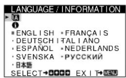
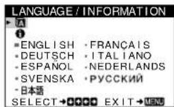
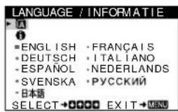
Selecting the on-screen menu language (LANGUAGE/INFORMATION)
English, French, German, Italian, Spanish, Dutch, Swedish, Russian and Japanese versions of the on-screen menus are available. The default setting is English.
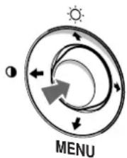
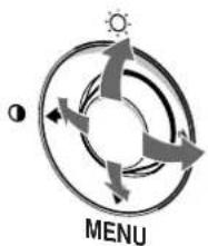
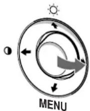
1 Press the center of the control button.
See page 9 for more information on using the control button.
flowchart
graph TD
    A["Sun Symbol"] --> B["Arrow Up"]
    B --> C["Arrow Down"]
    C --> D["Arrow Left"]
    D --> E["Arrow Right"]
    E --> F["Arrow Left"]
    F --> G["Arrow Down"]
    G --> H["Arrow Left"]
    H --> I["Arrow Right"]
    I --> J["Arrow Left"]
    J --> K["Arrow Down"]
    K --> L["Arrow Left"]
    L --> M["Arrow Down"]
    M --> N["Arrow Left"]
    N --> O["Arrow Down"]
    O --> P["Arrow Left"]
    P --> Q["Arrow Down"]
    Q --> R["Arrow Left"]
    R --> S["Arrow Down"]
    S --> T["Arrow Left"]
    T --> U["Arrow Down"]
    U --> V["Arrow Left"]
    V --> W["Arrow Down"]
    W --> X["Arrow Left"]
    X --> Y["Arrow Down"]
    Y --> Z["Arrow Left"]
    Z --> AA["Arrow Down"]
    AA --> AB["Arrow Left"]
    AB --> AC["Arrow Down"]
    AC --> AD["Arrow Left"]
    AD --> AE["Arrow Down"]
    AE --> AF["Arrow Left"]
    AF --> AG["Arrow Down"]
    AG --> AH["Arrow Left"]
    AH --> AI["Arrow Down"]
    AI --> AJ["Arrow Left"]
    AJ --> AK["Arrow Down"]
    AK --> AL["Arrow Left"]
    AL --> AM["Arrow Down"]
    AM --> AN["Arrow Left"]
    AN --> AO["Arrow Down"]
    AO --> AP["Arrow Left"]
    AP --> AQ["Arrow Down"]
    AQ --> AR["Arrow Left"]
    AR --> AS["Arrow Down"]
    AS --> AT["Arrow Left"]
    AT --> AU["Arrow Down"]
    AU --> AV["Arrow Left"]
    AV --> AW["Arrow Down"]
    AW --> AX["Arrow Left"]
    AX --> AY["Arrow Down"]
    AY --> AZ["Arrow Left"]
    AZ --> BA["Arrow Down"]
    BA --> BB["Arrow Left"]
    BB --> BC["Arrow Down"]
    BC --> BD["Arrow Left"]
    BD --> BE["Arrow Down"]
    BE --> BF["Arrow Left"]
    BF --> BG["Arrow Down"]
    BG --> BH["Arrow Left"]
    BH --> BI["Arrow Down"]
    BI --> BJ["Arrow Left"]
    BJ --> BK["Arrow Down"]
    BK --> BL["Arrow Left"]
    BL --> BM["Arrow Down"]
    BM --> BN["Arrow Left"]
    BN --> BO["Arrow Down"]
    BO --> BP["Arrow Left"]
    BP --> BQ["Arrow Down"]
    BQ --> BR["Arrow Left"]
    BR --> BS["Arrow Down"]
    BS --> BT["Arrow Left"]
    BT --> BU["Arrow Down"]
    BU --> BV["Arrow Left"]
    BV --> BW["Arrow Down"]
    BW --> BX["Arrow Left"]
    BX --> BY["Arrow Down"]
    BY --> BZ["Arrow Left"]
text_image
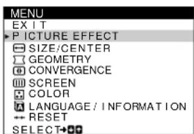
MENU EXIT PICTURE EFFECT SIZE/CENTER GEOMETRY CONVERGENCE SCREEN COLOR LANGUAGE / INFORMATION RESET SELECT+2 Move the control button ↓/↑ to highlight ☑ LANGUAGE/INFORMATION and press the center of the control button again.
flowchart
graph TD
    A["Sun Symbol"] --> B["Arrow Up"]
    B --> C["Arrow Down"]
    C --> D["Arrow Left"]
    D --> E["Arrow Right"]
    E --> F["Arrow Left"]
    F --> G["Arrow Right"]
    G --> H["Arrow Down"]
    H --> I["Arrow Left"]
    I --> J["Arrow Right"]
    J --> K["Arrow Down"]
    K --> L["Arrow Left"]
    L --> M["Arrow Right"]
    M --> N["Arrow Down"]
    N --> O["Arrow Left"]
    O --> P["Arrow Right"]
    P --> Q["Arrow Down"]
    Q --> R["Arrow Left"]
    R --> S["Arrow Right"]
    S --> T["Arrow Down"]
    T --> U["Arrow Left"]
    U --> V["Arrow Right"]
    V --> W["Arrow Down"]
    W --> X["Arrow Left"]
    X --> Y["Arrow Right"]
    Y --> Z["Arrow Down"]
text_image
LANGUAGE / INFORMATION ■ ENGLISH • FRANÇAIS • DEUTSCH ITALIANO • ESPAÑOL • NEDERLANDS • SVENSKA • РУССКИЙ • 日本語 SELECT→●●●●● EXIT→MENU3 Move the control button ↓/↑ to select A. Then move the control button ←/→ to select a language.
• ENGLISH
• FRANÇAIS: French
• DEUTSCH: German
• ITALIANO: Italian
- ESPAÑOL: Spanish
• NEDERLANDS: Dutch
• SVENSKA: Swedish
• :РУСОКИЙ
• : Japanese
To close the menu
Press the center of the control button once to return to the main MENU, and twice to return to normal viewing. If no buttons are pressed, the menu closes automatically after about 30 seconds.
To reset to English
See "Resetting the adjustments (RESET)" on page 11.
Customizing Your Monitor
You can make numerous adjustments to your monitor using the on-screen menu.
Navigating the menu
Press the center of the control button to display the main MENU on your screen. See page 9 for more information on using the control button.

flowchart
graph TD
    A["Sun"] --> B["Menu"]
    B --> C["Arrow 1"]
    B --> D["Arrow 2"]
    B --> E["Arrow 3"]
    B --> F["Arrow 4"]
    style A fill:#f9f,stroke:#333
    style B fill:#ccf,stroke:#333
    style C fill:#cfc,stroke:#333
    style D fill:#fcc,stroke:#333
    style E fill:#cff,stroke:#333
    style F fill:#ffc,stroke:#333
flowchart
graph TD
    A["1"] --> B["PICTURE EFFECT"]
    B --> C["SIZE/CENTER"]
    C --> D["GEOMETRY"]
    D --> E["CONVERGENCE"]
    E --> F["SCREEN"]
    F --> G["COLOR"]
    G --> H["LANGUAGE / INFORMAT NOI"]
    H --> I["RESET"]
    I --> J["SELECT"]
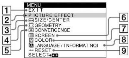
Use the control button to select one of the following menus.
1 EXIT
Select EXIT to close the menu.
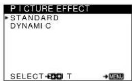
② PICTURE EFFECT (page 9)
Selects the PICTURE EFFECT menu to choose the most appropriate preset picture mode.
3 SIZE/CENTER (page 10)
Selects the SIZE/CENTER menu to adjust the picture's centering, size or zoom.
text_image
PICTURE EFFECT STANDARD DYNAMI C SELECT OFFSET T → MENU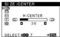
text_image
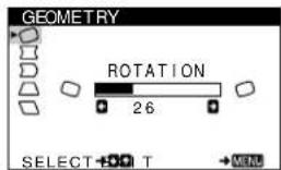
SIZE/CENTER H-CENTER 26 SELECT T → MENU4 GEOMETRY (page 10)
Select the GEOMETRY menu to adjust the picture's rotation and shape.
text_image
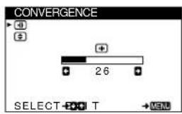
GEOMETRY ROTATION 26 SELECT + O T → MENS5 CONVERGENCE (page 10)
Selects the CONVERGENCE menu to adjust the picture's horizontal and vertical convergence.
text_image
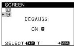
CONVERGENCE SELECT T MEN6 SCREEN (page 11)
Select the SCREEN menu to degauss the screen and adjust the moire cancellation level.
text_image
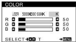
SCREEN DEGAUSS ON SELECT T →MENU7 COLOR (page 11)
Select the COLOR menu to adjust the picture's color temperature. You can use this to match the monitor's colors to a printed picture's colors.
8 LANGUAGE/INFORMATION
(page 7, 14)
Select the LANGUAGE/INFORMATION menu to choose the on-screen menu's language and display this monitor's information box.
text_image
LANGUAGE / INFORMATION • ENGLISH • FRANÇAIS • DEUTSCH • ITALIANO • ESPAÑOL • NEDERLANDS • SVENSKA • РУССКИЙ • 日本语 SELECT → ⚪→ ⚪→ EXIT → ⚪→ MENU9 RESET (page 11)
Select the RESET menu to reset the adjustments.
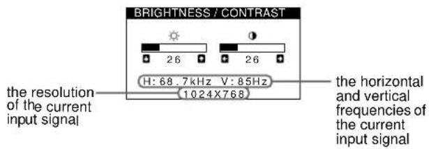
■ Displaying the current input signal
The horizontal and vertical frequencies of the current input signal are displayed under the BRIGHTNESS/CONTRAST menu. If the signal matches one of this monitor's factory preset modes, the resolution is also displayed.
text_image
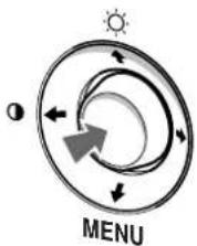
BRIGHTNESS / CONTRAST the resolution of the current input signal H: 68.7kHz V: 85Hz (1024X768) the horizontal and vertical frequencies of the current input signal■ Using the control button
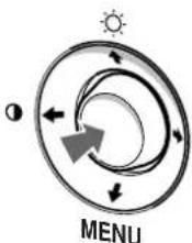
1 Display the main MENU.
Press the center of the control button to display the main MENU on your screen.
flowchart
graph TD
    A["Sun Symbol"] --> B((Circular Flow))
    B --> C["Arrow Up"]
    B --> D["Arrow Down"]
    B --> E["Arrow Left"]
    B --> F["Arrow Right"]
    B --> G["Arrow Left"]
    style A fill:#f9f,stroke:#333
    style B fill:#ccf,stroke:#333
    style C fill:#cfc,stroke:#333
    style D fill:#fcc,stroke:#333
    style E fill:#cff,stroke:#333
    style F fill:#ffc,stroke:#333
    style G fill:#cfc,stroke:#333
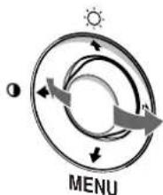
2 Select the menu you want to adjust.
Highlight the desired menu by moving the control button up (↑), down (↓), and left (←) or right (→).
flowchart
graph TD
    A["Sun Icon"] --> B["Arrow Left"]
    B --> C["Arrow Right"]
    C --> D["Arrow Bottom"]
    D --> E["Arrow Up"]
    E --> F["Arrow Left"]
    F --> G["Arrow Right"]
    G --> H["Arrow Bottom"]
    H --> I["Arrow Up"]
    I --> J["Arrow Left"]
    J --> K["Arrow Right"]
    K --> L["Arrow Bottom"]
    L --> M["Arrow Up"]
    M --> N["Arrow Left"]
    N --> O["Arrow Right"]
    O --> P["Arrow Bottom"]
    P --> Q["Arrow Up"]
    Q --> R["Arrow Left"]
    R --> S["Arrow Right"]
    S --> T["Arrow Bottom"]
    T --> U["Arrow Up"]
    U --> V["Arrow Left"]
    V --> W["Arrow Right"]
    W --> X["Arrow Bottom"]
    X --> Y["Arrow Up"]
    Y --> Z["Arrow Left"]
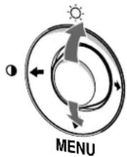
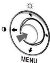
3 Adjust the menu.
Move the control button left ( ) or right ( ) to make the adjustment.
text_image
MENU4 Close the menu.
Press the center of the control button once to return to the main MENU, and twice to return to normal viewing. If no buttons are pressed, the menu closes automatically after about 30 seconds.
■ Resetting the adjustments
You can reset the adjustments using the RESET menu. See page 11 for more information on resetting the adjustments.
Adjusting the brightness and contrast
Brightness and contrast adjustments are made using a separate BRIGHTNESS/CONTRAST menu.
These settings are stored in memory for all input signals.
1 Move the control button in any direction.
The BRIGHTNESS/CONTRAST menu appears on the screen.
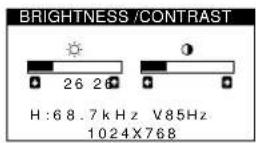
2 Move the control button ↓/↑ to adjust the brightness (○), and ←/→ to adjust the contrast (●).
The menu automatically disappears after about 3 seconds.
Adjusting the picture quality (PICTURE EFFECT)
The PICTURE EFFECT feature allows you to select the most appropriate picture mode from among two preset modes maximum performance.
1 Press the center of the control button.
The main MENU appears on the screen.
2 Move the control button to highlight PICTURE EFFECT and press the center of the control button again.
The PICTURE EFFECT menu appears on the screen.
3 Move the control button ↓/↑ to select the desired picture mode.
| Select For | |
| STANDARD | images with high contrast and brightness. Choose this mode for commonly used applications, such as spreadsheets, word processing, E-mail, or WEB surfing. |
| DYNAMIC | extremely vivid and photo-realistic images. Brighter than “STANDARD” mode, choose this for intense graphic applications such as games, DVD playback, or entertainment software. |
Adjusting the centering of the picture (CENTER)
This setting is stored in memory for the current input signal.
1 Press the center of the control button. The main MENU appears on the screen.
2 Move the control button ↓/↑ to highlight SIZE/CENTER and press the center of the control button again.
The SIZE/CENTER menu appears on the screen.
3 First move the control button ↓/↑ to select
☐ (H-CENTER) for horizontal adjustment, or
☐ (V-CENTER) for vertical adjustment. Then move the control button ←/→ to adjust the centering.
Adjusting the size of the picture (SIZE)
This setting is stored in memory for the current input signal.
1 Press the center of the control button. The main MENU appears on the screen.
2 Move the control button ↓/↑ to highlight SIZE/CENTER and press the center of the control button again.
The SIZE/CENTER menu appears on the screen.
3 First move the control button ↓/↑ to select
↔ (H-SIZE) for horizontal adjustment, or
↔ (V-SIZE) for vertical adjustment. Then move the control button ←/→ to adjust the size.
Enlarging or reducing the picture (ZOOM)
This setting is stored in memory for the current input signal.
1 Press the center of the control button. The main MENU appears on the screen.
2 Move the control button ↓/↑ to highlight SIZE/CENTER and press the center of the control button again.
The SIZE/CENTER menu appears on the screen.
3 Move the control button ↓/↑ to select (ZOOM), and move ←/→ to enlarge or reduce the picture.
Adjusting the shape of the picture (GEOMETRY)
The GEOMETRY settings allow you to adjust the rotation and shape of the picture.
The (ROTATION) setting is stored in memory for all input signals. All other settings are stored in memory for the current input signal.
1 Press the center of the control button. The main MENU appears on the screen.
2 Move the control button ↓/↑ to highlight □ GEOMETRY and press the center of the control button again.
The GEOMETRY menu appears on the screen.
3 First move the control button ↓/↑ to select the desired adjustment item. Then move the control button ←/→ to make the adjustment.
| Select To | |
| ☐ (ROTATION) | rotate the picture |
| ☐ (PIN) | expand or contract the picture sides |
| ☐ (PIN BALANCE) | shift the picture sides to the left or right |
| ☐ (KEY) | adjust the picture width at the top of the screen |
| ☐ (KEY BALANCE) | shift the picture to the left or right at the top of the screen |
Adjusting the convergence (CONVERGENCE)
The CONVERGENCE settings allow you to adjust the quality of the picture by controlling the convergence. The convergence refers to the alignment of the red, green, and blue color signals. If you see red or blue shadows around letters or lines, adjust the convergence.
These settings are stored in memory for all input signals.
1 Press the center of the control button. The main MENU appears on the screen.
2 Move the control button ↓/↑ to highlight ➕ CONVERGENCE and press the center of the control button again.
The CONVERGENCE menu appears on the screen.
3 First move the control button ↓/↑ to select the desired adjustment item. Then move the control button ←/→ to make the adjustment.
| Select To | |
| horizontally shift red or blue shadows | |
| vertically shift red or blue shadows | |
Adjusting the color of the picture (COLOR)
The COLOR settings allow you to adjust the picture's color temperature by changing the color level of the white color field. Colors appear reddish if the temperature is low, and bluish if the temperature is high. This adjustment is useful for matching the monitor's colors to a printed picture's colors. This setting is stored in memory for all input signals.
1 Press the center of the control button. The main MENU appears on the screen.
2 Move the control button ↓/↑ to highlight 📁 COLOR and press the center of the control button again.
The COLOR menu appears on the screen.
3 Move the control button / to select a color temperature. The preset color temperatures are 5000K, 6500K, and 9300K. Since the default setting is 9300K, the whites will change from a bluish hue to a reddish hue as the temperature is lowered to 6500K and 5000K.
4 If necessary, fine tune the color temperature.
First move the control button ←/→ to select USER. Then move the control button ↓/↑ to select R (red), G (green), or B (blue) and move the control button ←/→ to make the adjustment.
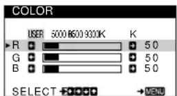
If you fine tune the color temperature, the new color settings are stored in memory and recalled whenever you select USER.
Additional settings (SCREEN)
You can manually degauss (demagnetize) the screen, and adjust the moire cancellation level.
1 Press the center of the control button. The main MENU appears on the screen.
2 Move the control button ↓/↑ to highlight 📄 SCREEN and press the center of the control button again.
The SCREEN menu appears on the screen.
3 Move the control button ↓/↑ to select the desired adjustment item.
Adjust the selected item according to the following instructions.
■ Degaussing the screen
The monitor is automatically demagnetized when the power is turned on.
To manually degauss the monitor, first move the control button ↓/↑ to select ⬆ (DEGAUSS). Then move the control button →.
The screen is degaussed for about 5 seconds. If a second degauss cycle is needed, allow a minimum interval of 20 minutes for the best result.
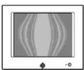
■ Adjusting the moire\*
If elliptical or wavy patterns appear on the screen, adjust the moire cancellation level.
To adjust the amount of moire cancellation, first move the control button ↓/↑ to select (CANCEL MOIRE). Then move the control button ←/→ until the moire effect is at a minimum.
* Moire is a type of natural interference which produces soft, wavy lines on your screen. It may appear due to interference between the pattern of the picture on the screen and the phosphor pitch pattern of the monitor.
Example of moire
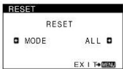
Resetting the adjustments (RESET)
This monitor has the following two reset methods. Use the RESET menu to reset the adjustments.
1 Press the center of the control button. The main MENU appears on the screen.
2 Move the control button ↓/↑ to highlight →← RESET and press the center fo the control button again. The RESET menu appears on the screen. Reset the settings according to the following instructions.
Resetting all of the adjustment data for the current input signal (MODE)
Move the control button ←.
The MODE item is selected. All of the adjustment data for the current input signal is reset. Note that the following items are not reset by this method. • on-screen menu language (page 7) • picture's rotation (page 10)
Resetting all of the adjustment data to factory preset levels (ALL)
Move the control button →.
The ALL item is selected. All of the adjustment data for the current input signal is reset. All of the adjustment data (except for the USER settings in the COLOR menu) is reset to the factory preset levels.
Note
The monitor's buttons will not operate for about 5 seconds when ALL is selected.
Technical Features
Preset and user modes
When the monitor receives an input signal, it automatically matches the signal to one of the factory preset modes stored in the monitor's memory to provide a high quality picture at the center of the screen. (See Appendix for a list of the factory preset modes.) For input signals that do not match one of the factory preset modes, the digital Multiscan technology of this monitor ensures that a clear picture appears on the screen for any timing in the monitor's frequency range (horizontal: 30 – 96 kHz, vertical: 48 – 120 Hz). If the picture is adjusted, the adjustment data is stored as a user mode and automatically recalled whenever the same input signal is received.
Note for Windows users
For Windows users, check your video board manual or the utility program which comes with your graphic board and select the highest available refresh rate to maximize monitor performance.
Power saving function
This monitor meets the power-saving guidelines set by VESA, ENERGY STAR, and NUTEK. If no signal is received by the monitor from the connected computer, the monitor will automatically reduce power consumption as shown below.
| Power mode | Power consumption* | 1 (power) indicator |
| normal operation | ≤ 150 W green | |
| active off** ≤ 3 W orange | ||
| power off 0 W off | ||
* Figures reflect power consumption when no USB compatible peripherals are connected to the monitor.
** When your computer enters the "active off" mode, the input signal is cut and NO INPUT SIGNAL appears on the screen. After 20 seconds, the monitor enters the power saving mode.
Troubleshooting
Before contacting technical support, refer to this section.
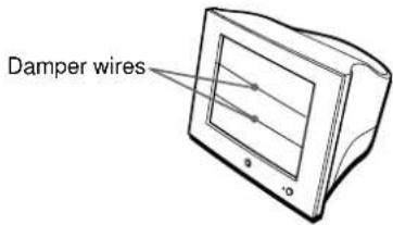
If thin lines appear on your screen (damper wires)
The visible lines on your screen especially when the background screen color is light (usually white), are normal for the Trinitron monitor. This is not a malfunction. These are shadows from the damper wires used to stabilize the aperture grille. The aperture grille is the essential element that makes a Trinitron picture tube unique by allowing more light to reach the screen, resulting in a brighter, more detailed picture.
text_image
Damper wiresOn-screen messages
If there is something wrong with the input signal, one of the following messages appears on the screen. To solve the problem, see “Trouble symptoms and remedies” on page 13.
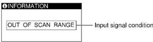
text_image
INFORMATION OUT OF SCAN RANGE——Input signal conditionThe input signal condition
OUT OF SCAN RANGE
indicates that the input signal is not supported by the monitor's specifications.
NO INPUT SIGNAL
indicates that no signal is being input to the monitor.
Trouble symptoms and remedies
If the problem is caused by the connected computer or other equipment, please refer to the connected equipment's instruction manual.
Use the self-diagnosis function (page 15) if the following recommendations do not resolve the problem.
| Symptom Check these items | |
| No picture | |
| If the 1 (power) indicator is not lit | Check that the power cord is properly connected.Check that the 1 (power) switch is in the “on” position. |
| If the NO INPUT SIGNAL message appears on the screen, or if the 1 (power) indicator is orange | Check that the video signal cable is properly connected and all plugs are firmly seated in their sockets (page 6).Check that the HD15 video input connector’s pins are not bent or pushed in.■Problems caused by the connected computer or other equipmentThe computer is in power saving mode. Try pressing any key on the computer keyboard or moving the mouse.Check that the computer’s power is “on.”Check that the graphic board is completely seated in the proper bus slot. |
| If the OUT OF SCAN RANGE message appears on the screen | ■Problems caused by the connected computer or other equipmentCheck that the video frequency range is within that specified for the monitor. If you replaced an old monitor with this monitor, reconnect the old monitor and adjust the frequency range to the following.Horizontal: 30 – 96 kHzVertical: 48 – 120 Hz |
| If no message is displayed and the 1 (power) indicator is green or flashing orange | Use the Self-diagnosis function (page 15). |
| If using a Macintosh system • Check that the Macintosh adapter (not supplied) and the video signal cable are properly connected (page 6). | |
| Picture flickers, bounces, oscillates, or is scrambled | Isolate and eliminate any potential sources of electric or magnetic fields such as other monitors, laser printers, electric fans, fluorescent lighting, or televisions.Move the monitor away from power lines or place a magnetic shield near the monitor.Try plugging the monitor into a different AC outlet, preferably on a different circuit.Try turning the monitor 90° to the left or right.■Problems caused by the connected computer or other equipmentCheck your graphics board manual for the proper monitor setting.Confirm that the graphics mode (VESA, etc.) and the frequency of the input signal are supported by this monitor (Appendix). Even if the frequency is within the proper range, some video boards may have a sync pulse that is too narrow for the monitor to sync correctly.Adjust the computer’s refresh rate (vertical frequency) to obtain the best possible picture. |
| Picture is fuzzy • Adjust the brightness and contrast (page 9).Degauss the monitor* (page 11).Select CANCEL MOIRE and adjust the moire cancellation effect (page 11). | |
| Picture is ghosting | Eliminate the use of video cable extensions and/or video switch boxes.Check that all plugs are firmly seated in their sockets. |
| Picture is not centered or sized properly | Adjust the size (page 10) or centering (page 10). Note that some video modes do not fill the screen to the edges. |
| Edges of the image are curved • Adjust the geometry (page 10). | |
| Wavy or elliptical pattern (moire) is visible | Select CANCEL MOIRE and adjust the moire cancellation effect (page 11).■Problems caused by the connected computer or other equipmentChange your desktop pattern. |
(Continued)
| Symptom Check these items | |
| Color is not uniform | • Degauss the monitor* (page 11). If you place equipment that generates a magnetic field, such as a speaker, near the monitor, or if you change the direction the monitor faces, color may lose uniformity. |
| White does not look white | • Adjust the color temperature (page 11). |
| Letters and lines show red or blue shadows at the edges | • Adjust the convergence (page 10). |
| USB peripherals do not function | • Check that the appropriate USB connectors are securely connected (page 7).• Check that the 1 (power) switch is in the “on” position.■ Problems caused by the connected computer or other equipment• Check that the power of any self-powered USB compliant peripheral devices is “on.”• Install the latest version of the device driver on your computer. Contact your device’s manufacturer for information about the appropriate device driver.• If your USB compliant keyboard or mouse does not function, connect them directly to your computer, reboot your computer, and make any necessary adjustments to the USB settings. Then reconnect the keyboard or mouse to the monitor. If you connect a keyboard or mouse to the USB connectors and then boot your computer for the first time, the peripheral devices may not function.• For customers using Windows 951. Right-click on My Computer and select Properties.2. Click on the Device Manager tab. Scroll down and select Universal Serial Bus Controller.If Universal Serial Bus Controller does not appear, you need to load a USB supplement disk. Contact your computer’s manufacturer for more information about obtaining a USB supplement disk.3. Select Generic USB Device from the USB controller list and click on Properties.4. If there is a check in the box next to “Disable in this hardware profile,” remove the check.5. Click on Refresh. |
| A hum is heard right after the power is turned on | • This is the sound of the auto-degauss cycle. When the power is turned on, the monitor is automatically degaussed for five seconds. |
* If a second degauss cycle is needed, allow a minimum interval of 20 minutes for the best result. A humming noise may be heard, but this is not a malfunction.
Displaying this monitor's name, serial number, and date of manufacture
1 Press the center of the control button.
The main MENU appears on the screen.
2 Move the control button ↓/↑ to highlight ☑ LANGUAGE/INFORMATION and press the center of the control button.
The LANGUAGE/INFORMATION menu appears on the screen.
3 Move the control button ↓/↑ to select ⓘ
This monitor's information menu appears on the screen.
Example
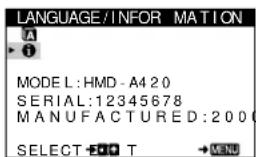
text_image
LANGUAGE/INFORMATION A ► i MODEL: HMD - A4 20 SERIAL: 12345678 MANUFACTURED: 2000 SELECT → T → MENUIf the problem persists, call your authorized Sony dealer and give the following information.
- Model name: HMD-A420
- Serial number
- Name and specifications of your computer and graphics board.
Self-diagnosis function
This monitor is equipped with a self-diagnosis function. If there is a problem with your monitor or computer, the screen will go blank and the ① (power) indicator will either light up green or flash orange. If the ① (power) indicator is lit in orange, the computer is in power saving mode. Try pressing any key on the keyboard.
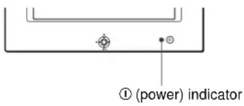
text_image
(① (power) indicatorIf the ① (power) indicator is green
1 Disconnect the video input cable or turn off the connected computer.
2 Press the ① (power) button twice to turn the monitor off and then on.
3 Move the control button → for 2 seconds before the monitor enters power saving mode.
flowchart
graph TD
    A["Sun"] --> B["Arrow Left"]
    B --> C["Arrow Right"]
    C --> D["Arrow Down"]
    D --> E["Arrow Up"]
    E --> F["Arrow Left"]
    style A fill:#f9f,stroke:#333
    style F fill:#f9f,stroke:#333
    style B fill:#ccf,stroke:#333
    style C fill:#ccf,stroke:#333
    style D fill:#ccf,stroke:#333
    style E fill:#ccf,stroke:#333
    style F fill:#ccf,stroke:#333
If all four color bars appear (white, red, green, blue), the monitor is working properly. Reconnect the video input cable and check the condition of your computer.
If the color bars do not appear, there is a potential monitor failure. Inform your authorized Sony dealer of the monitor's condition.
If the ① (power) indicator is flashing orange
Press the ① (power) button twice to turn the monitor off and then on.
If the ① (power) indicator lights up green, the monitor is working properly.
If the ① (power) indicator is still flashing, there is a potential monitor failure. Count the number of seconds between orange flashes of the ① (power) indicator and inform your authorized Sony dealer of the monitor's condition. Be sure to note the model name and serial number of your monitor. Also note the make and model of your computer and video board.
Specifications
CRT 0.24 mm aperture grille pitch (center)
19 inches measured diagonally
90-degree deflection
FD Trinitron
Viewable image size Approx. 365 · 274 mm (w/h)
(14 ^3 /8 · 10 ^7 /8 inches)
18.0" viewing image
Resolution
Maximum Horizontal: 1800 dots
Vertical: 1440 lines
Recommended Horizontal: 1280 dots
Vertical: 1024 lines
Standard image area Approx. 352 · 264 mm (w/h)
(13 ^7 /8 · 10 ^1 /2 inches)
Deflection frequency* Horizontal: 30 to 96 kHz
Vertical: 48 to 120 Hz
AC input voltage/current 100 - 240 V, 50 - 60 Hz, 2.3 - 1.0 A
Power consumption Max. 150 W
Dimensions Approx. 497 · 458 · 469 mm
(w/h/d)
(19^5/8 · 18^1/8 · 18^1/2 inches)
Mass Approx. 26 kg (57 lb 5 oz)
Plug and Play DDC1/DDC2B/DDC2Bi
Supplied accessories See page 6
* Recommended horizontal and vertical timing condition
• Horizontal sync width should be more than 1.0 μsec.
• Horizontal blanking width should be more than 3.0 μsec.
• Vertical blanking width should be more than 500 μsec.
Design and specifications are subject to change without notice.
Table des Matières
Précautions....4
natural_image
Diagram showing car interior components including dashboard, brush, and seat cover (no text or symbols)natural_image
Top-down diagram of a car interior showing dashboard, steering wheel, and three front-mounted switches (no text or labels)text_image
GEOMETRIE ROTATION 26 SELECT EDIT MEN5 CONVERGENCE (page 10)
natural_image
Line drawing of a computer monitor with screen and cables (no text or symbols)Plug & Play DDC1/DDC2B/DDC2Bi
natural_image
Diagram showing car interior components including dashboard, brush, and seat cover (no text or labels)text_image
KONVERGENZ SELECT + - + T → MEVUflowchart
graph TD
    A["Sun Symbol"] --> B["Arrow Up"]
    B --> C["Arrow Down"]
    C --> D["Arrow Left"]
    D --> E["Arrow Right"]
    E --> F["Arrow Left"]
    F --> G["Arrow Down"]
    G --> H["Arrow Up"]
    H --> I["Arrow Down"]
    I --> J["Arrow Left"]
    J --> K["Arrow Down"]
    K --> L["Arrow Left"]
    L --> M["Arrow Down"]
    M --> N["Arrow Left"]
    N --> O["Arrow Down"]
    O --> P["Arrow Left"]
    P --> Q["Arrow Down"]
    Q --> R["Arrow Left"]
    R --> S["Arrow Down"]
    S --> T["Arrow Left"]
    T --> U["Arrow Down"]
    U --> V["Arrow Left"]
    V --> W["Arrow Down"]
    W --> X["Arrow Left"]
    X --> Y["Arrow Down"]
    Y --> Z["Arrow Left"]
    Z --> AA["Arrow Down"]
    AA --> AB["Arrow Left"]
    AB --> AC["Arrow Down"]
    AC --> AD["Arrow Left"]
    AD --> AE["Arrow Down"]
    AE --> AF["Arrow Left"]
    AF --> AG["Arrow Down"]
    AG --> AH["Arrow Left"]
    AH --> AI["Arrow Down"]
    AI --> AJ["Arrow Left"]
    AJ --> AK["Arrow Down"]
    AK --> AL["Arrow Left"]
    AL --> AM["Arrow Down"]
    AM --> AN["Arrow Left"]
    AN --> AO["Arrow Down"]
    AO --> AP["Arrow Left"]
    AP --> AQ["Arrow Down"]
    AQ --> AR["Arrow Left"]
    AR --> AS["Arrow Down"]
    AS --> AT["Arrow Left"]
    AT --> AU["Arrow Down"]
    AU --> AV["Arrow Left"]
    AV --> AW["Arrow Down"]
    AW --> AX["Arrow Left"]
    AX --> AY["Arrow Down"]
    AY --> AZ["Arrow Left"]
    AZ --> BA["Arrow Down"]
    BA --> BB["Arrow Left"]
    BB --> BC["Arrow Down"]
    BC --> BD["Arrow Left"]
    BD --> BE["Arrow Down"]
    BE --> BF["Arrow Left"]
    BF --> BG["Arrow Down"]
    BG --> BH["Arrow Left"]
    BH --> BI["Arrow Down"]
    BI --> BJ["Arrow Left"]
    BJ --> BK["Arrow Down"]
    BK --> BL["Arrow Left"]
    BL --> BM["Arrow Down"]
    BM --> BN["Arrow Left"]
    BN --> BO["Arrow Down"]
    BO --> BP["Arrow Left"]
    BP --> BQ["Arrow Down"]
    BQ --> BR["Arrow Left"]
    BR --> BS["Arrow Down"]
    BS --> BT["Arrow Left"]
    BT --> BU["Arrow Down"]
    BU --> BV["Arrow Left"]
    BV --> BW["Arrow Down"]
    BW --> BX["Arrow Left"]
    BX --> BY["Arrow Down"]
    BY --> BZ["Arrow Left"]
Plug and Play DDC1/DDC2B/DDC2Bi
natural_image
Technical line drawings of car interior components including dashboard, brush, and seat cover (no text or symbols)natural_image
Diagram of a computer monitor front view with three labeled ports (no text or symbols present)Plug and Play DDC1/DDC2B/DDC2Bi
natural_image
Line drawings of three different types of electrical plugs (no text or symbols present)da 100 a 120 V CA da 200 a 240 V CA solo 240 V CA
natural_image
Diagram showing car interior components including dashboard, brush, and seat cover (no text or symbols)text_image
Diagram showing two labeled components (1 and 2) connected by lines, with symbols indicating input/output ports.flowchart
graph TD
    A["Sun"] --> B{Menu}
    B --> C["Directional Arrow 1"]
    B --> D["Directional Arrow 2"]
    B --> E["Directional Arrow 3"]
    B --> F["Directional Arrow 4"]
    B --> G["Directional Arrow 5"]
    style A fill:#f9f,stroke:#333
    style B fill:#ccf,stroke:#333
natural_image
Line drawing of a computer monitor with screen and cables (no text or symbols)Messaggi a schermo
Plug and Play DDC1/DDC2B/DDC2Bi
natural_image
Diagram showing car interior components including dashboard, brush, and seat cover (no text or labels)natural_image
Diagram of a car interior with three labeled compartments (no text or symbols present)flowchart
graph TD
    A["Sun Icon"] --> B["Arrow Up"]
    B --> C["Arrow Down"]
    C --> D["MENU"]
    style A fill:#f9f,stroke:#333
    style D fill:#bbf,stroke:#333
■ Сброс настроек
Plug and Play DDC1/DDC2B/DDC2Bi
natural_image
Technical line drawings of a car interior showing exterior and side views with no text or symbolsnatural_image
Diagram of a computer monitor with three labeled ports and an open rear panel (no text or symbols present)till USB-
kompatibel
periferiutrustning
till USB-kompatibel dator
till USB-
kompatibel
periferiutrustning
flowchart
graph TD
    A["Sun Icon"] --> B["Menu"]
    B --> C["Directional Arrows"]
    C --> D["Arrow Down"]
    D --> E["Arrow Up"]
    E --> F["Arrow Left"]
    F --> G["Arrow Right"]
    G --> H["Arrow Down"]
    H --> I["Arrow Up"]
    I --> J["Arrow Left"]
    J --> K["Arrow Right"]
    K --> L["Arrow Down"]
    L --> M["Arrow Up"]
    M --> N["Arrow Left"]
    N --> O["Arrow Right"]
    O --> P["Arrow Down"]
    P --> Q["Arrow Up"]
    Q --> R["Arrow Left"]
    R --> S["Arrow Right"]
    S --> T["Arrow Down"]
    T --> U["Arrow Up"]
    U --> V["Arrow Left"]
    V --> W["Arrow Right"]
    W --> X["Arrow Down"]
    X --> Y["Arrow Up"]
    Y --> Z["Arrow Left"]
flowchart
graph TD
    A["Sun Symbol"] --> B((Menu))
    B --> C["Arrow Left"]
    B --> D["Arrow Right"]
    B --> E["Arrow Down"]
    B --> F["Arrow Up"]
    style A fill:#f9f,stroke:#333
    style B fill:#ccf,stroke:#333
    style C fill:#cfc,stroke:#333
    style D fill:#fcc,stroke:#333
    style E fill:#cff,stroke:#333
    style F fill:#ffc,stroke:#333
3 Justera menyn.
Plug and Play DDC1/DDC2B/DDC2Bi
Specifications....15
Appendix....i
Preset mode timing table ....i
natural_image
Technical line drawings of a car interior showing exterior and side views with no text or symbolstext_image
Diagram showing two labeled components (1 and 2) connected by lines, with symbols indicating input/output ports.5 USB (universal serial bus) downstream connectors (pagina 7)
6 USB (universal serial bus) upstream connector (pagina 7)
IBM PC/AT of compatibele computer
Macintosh of compatibele computer
text_image
SCHERM DEMAGN . AA + SELECT - E O T → M E N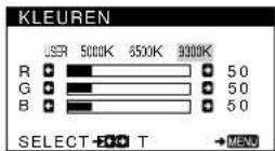
text_image
LANGUAGE / INFORMATIE • ENGLISH • FRANÇAIS • DEUTSCH • ITALIANO • ESPAÑOL • NEDERLANDS • SVENSKA • РУССКИЙ • 日本語 SELECT → XXXX EXIT → MENU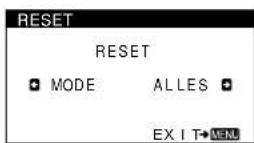
active off** ≤ 3 W oranje
uit 0 W uit
Plug and Play DDC1/DDC2B/DDC2Bi
Meegeleverde toebehoren Zie pagina 6
* Aanbevolen horizontale en verticale timing